Page is loading ...

ID TECH
10721 Walker Street, Cypress, CA 90630-4720
Tel: (714) 761-6368 Fax (714) 761-8880
www.idtechproducts.com
ViVOpay™ VP5300M Integration Manual
80171500-001 Rev. P
14 August 2023

ID TECH VP5300M Integration Manual
Page | 2
Copyright 2023 International Technologies and Systems Corporation. All rights reserved.
ID TECH
10721 Walker Street
Cypress, CA 90630 USA
This document, as well as the hardware and software it describes, is furnished under license and may only be used in
accordance with the terms of such license. The content of this paper is furnished for informational use, subject to change
without notice, and not to be construed as a commitment by ID TECH. ID TECH assumes no responsibility or liability for any
errors or inaccuracies that may appear in this document.
Except as permitted by such license, no part of this publication may be reproduced or transmitted by electronic, mechanical,
recorded, or any other method, or translated into another language or language form without the express written consent
of ID TECH. ID TECH is a registered trademark of International Technologies and Systems Corporation. ViVOpay and Value
through Innovation are trademarks of International Technologies and Systems Corporation. Other trademarks are the
property of the respective owner.
Warranty Disclaimer: The services and hardware are provided "as is" and "as-available," and the use of these services and
hardware are at the user’s own risk. ID TECH does not make, and hereby disclaims, any and all other express or implied
warranties, including, but not limited to warranties of merchantability, title, fitness for a particular purpose, and any
warranties arising from any course of dealing, usage, or trade practice. ID TECH does not warrant that the services or
hardware will be uninterrupted, error-free, or completely secure.
CAUTION: Risk of Explosion if Battery is replaced by an Incorrect Type. Dispose of Used Batteries
According to the Instructions.

ID TECH VP5300M Integration Manual
Page | 3
Revision History
Date
Revision
Changes
Author
04/07/2021
L
Reimplemented Revision History log
Restored Applicable Documents section
CB
06/30/2021
Added section about SmartPIN L100 removal detection sensor
CB
10/07/2021
M
Updated Diagnostic LED Status table
CB
12/01/2021
N
Updated cleaning information, added notes about outdoor
installation requirements
CB
08/01/2022
O
Added battery warning text to preamble.
CB
08/14/2023
P
Updated external links.
CB

ID TECH VP5300M Integration Manual
Page | 4
Table of Contents
1. OVERVIEW ....................................................................................................................................................................... 6
1.1. Applicable Documents .................................................................................................................................................... 7
1.2. Features .............................................................................................................................................................................. 7
1.3. VP5300M: Approvals ....................................................................................................................................................... 8
2. VP5300M ELECTRICAL REQUIREMENTS ..................................................................................................................... 9
3. VP5300M SPECIFICATIONS ........................................................................................................................................... 9
4. VP5300M 3-VIEW DRAWING ...................................................................................................................................... 11
5. NFC ANTENNA 3-VIEW ................................................................................................................................................ 13
6. VP5300M INSTALLATION ............................................................................................................................................ 14
6.1. Parts List .......................................................................................................................................................................... 14
6.2. Installing the Reader ..................................................................................................................................................... 14
6.2.1. Protective Plastic Film .......................................................................................................................................................................... 14
6.3. Mounting the VP5300M External NFC Antenna .................................................................................................. 15
6.3.1. Flush-Mounting the Antenna ........................................................................................................................................................... 18
6.4. VP5300M Connectors .................................................................................................................................................. 18
6.5. Attaching the Cables from the Antenna to the VP5300M ................................................................................ 19
6.6. Connecting to Power .................................................................................................................................................... 19
6.7. Connecting to the Data Port ....................................................................................................................................... 20
6.8. VP5300M External Cable Pin Assignments: RS-232 ......................................................................................... 20
6.9. VP5300M External Cable Pin Assignments: USB ................................................................................................ 20
6.10. Installation Notes ........................................................................................................................................................ 21
7. LED MANAGEMENT ...................................................................................................................................................... 22
7.1. Front LED Status ............................................................................................................................................................ 22
7.2. RF LED Status ................................................................................................................................................................. 22
7.3. Diagnostic LED Status .................................................................................................................................................. 23
8. WARPED CARD SUPPORT ............................................................................................................................................ 23
9. USING THE VP5300M TO MAKE A CONTACTLESS PURCHASE ............................................................................... 24
9.1. Presenting Proximity Cards or NFC Phones .......................................................................................................... 24
10. MAINTENANCE ............................................................................................................................................................ 25
10.1. Cleaning the VP5300M ............................................................................................................................................. 25
10.1.1. Cleaning the Magnetic Heads ....................................................................................................................................................... 25
10.1.2. Cleaning the Transportation Rollers ........................................................................................................................................ 25
10.1.3. Cleaning Guidelines ............................................................................................................................................................................. 27
11. PAIRING WITH PIN PAD ............................................................................................................................................. 28
11.1. Setting up the L100 or L80 ...................................................................................................................................... 28
11.2. Setting up the VP5300M .......................................................................................................................................... 29
11.3. Pair the Devices ........................................................................................................................................................... 32
11.3.1. Enabling SmartPIN L100 Devices ............................................................................................................................................. 34
11.3.2. Enabling SmartPIN L80 Devices ................................................................................................................................................. 35
11.4. L100 Removal Detection and Paired Readers ................................................................................................... 35
12. RF INTERFERENCE ..................................................................................................................................................... 36
13. UPDATING VP5300M FIRMWARE ............................................................................................................................ 37
14. TROUBLESHOOTING ................................................................................................................................................... 39
15. TAMPER AND FAILED SELF-CHECK INDICATORS .................................................................................................. 41

ID TECH VP5300M Integration Manual
Page | 5
16. FCC WARNING STATEMENT ...................................................................................................................................... 42
17. IC COMPLIANCE WARNING ....................................................................................................................................... 43
18. CAUTIONS AND WARNINGS ...................................................................................................................................... 43

ID TECH VP5300M Integration Manual
Page | 6
1. Overview
ID TECH's VP5300M is a motorized, compact SRED credit card reader designed to support MSR
(MagStripe) and contact EMV, plus contactless EMV (when the device is mated with the VP5300M’s
NFC antenna).
The VP5300M is designed to deliver MSR, EMV, and optional NFC (contactless) payment acceptance
with SRED security and reliability in unattended payment scenarios, such as Parking, ATM, Ticketing,
and Payment Kiosks (among others)1.
The VP5300M leads the industry in low power consumption and ruggedness, with its plastic bezel
and IK07 and IP42 ratings to ensure long life in demanding conditions. The VP5300M is certified to
the latest payment standards of EMV (Level 1 and Level 2) and PCI (5.x) and offers easy integration of
payments into self-serve kiosk and unattended environments.
The VP5300M
NFC Antenna
1 The VP5300M is not for use in outdoor scenarios unless equipped with a cover or shed to protect the reader
from water or snow intrusion. Although the product is IK07 and IP42 rated, it cannot withstand water or snow
intrusion in outdoor environments.

ID TECH VP5300M Integration Manual
Page | 7
The VP5300M supports USB and serial (RS-232) host communication using the command protocol
defined in the NEO 2 Interface Developers Guide. This comprehensive guide describes all the firmware
commands and other features available in ID TECH's NEO-series devices; it is the authoritative source
for technical information of interest to systems integrators. Contact your ID TECH representative to
obtain a copy of this guide, which is available under NDA. Note, also, that a feature-rich, Windows-
based Universal SDK is available to aid in rapid development of applications that talk to the
VP5300M.
Be sure to check the VP5300 product page on the ID TECH Knowledge Base for the latest VP5300M
demos, utilities, SDK updates, white papers, and other downloads, all of which are freely available
without registration.
NOTE: The VP5300M requires the use of an external 12V DC power supply; it cannot run on USB port
power alone. When other peripherals are connected to it, such as an NFC antenna, the VP5300M
powers those peripherals.
1.1. Applicable Documents
• ISO 7810 Identification cards: Physical characteristics
• ISO 7811 1 - 6 Identification Cards: Track 1 - 3
• ISO 7816 Identification cards: Integrated circuit cards
• ISO 4909 Magnetic stripe content for track 3
• 80171400 Product Requirement Document: Motorized PCI SRED / EMV Insert Reader
• 80000403-001 Enhanced Encrypted MSR Data Output Format
• 80000404-001 ID-Tech Encrypt Data Format in Command Response Specification
• 80000405-001 IDTECH NGA Key Injection Protocol
1.2. Features
The VP5300M supports the following features:
• Contactless: ISO/IEC 14443 Type A and B
• PCI-PTS 5.x certification with SRED
• Tamper responsive (with automatic zeroization of keys in the event of tamper)
• MSR reads up to 3 tracks of data (Bi-Directional), with JIS-I and JIS-II support
• ICC reader with landing contact
• Contact and Contactless EMV Level 1 certified
o Contact EMV Level 2 certified, using ID TECH's proven Common Kernel
o All major Contactless kernels supported
• State-of-the-art encryption support
o Triple DES
o AES
o TransArmor RSA
• Support for DUKPT key management (with 15 DUKPT slots) of data and/or MAC keys
• NGA Key Injection Protocol

ID TECH VP5300M Integration Manual
Page | 8
• TR34 Remote Key Injection Protocol
• 32 Key slots supported
• Optional contactless (NFC/RFID) antenna
• Mechanical and optical combination front switch
• Plastic bezel with a gate
• Dedicated RS232, USB, and Ethernet ports (for data communication)
• Dedicated DC 12 to 24V power input
• LAN with network function 2 colored LEDs for link state and speed indication
• Audio feedback for MSR, contact EMV, and contactless transactions
• RoHS 2, and REACH compliance
• 1-year manufacturer's warranty
This document assumes that users are familiar with their host systems and all related functions.
1.3. VP5300M: Approvals
Item
Regulation & Class
CE
EN55032/EN55035, Class- B
FCC
Part 15, Class-B
RoHS
Compliant
UL
Certification with UL regulation
REACH
Compliance with REACH regulation
USB IF
Compliance with USB IF regulation
EMV
Contact L1 & L2 / Contactless L1
PCI
PCI PTS 5.X Certified
Contactless Technology
Specification Compliance
American Express
American Express® ExpressPay 3.1
Discover
Discover® DPAS 1.0 Zip 3.1.2
MasterCard
MasterCard® MChip 3.1.1
Visa
Visa VCPS 2.2
Interac
Interac 1.5d
CUP
qPBOC 3.0 (ongoing)
JCB
JCB 1.4 (ongoing)
Mobile wallets
Apple Pay
Apple VAS
Android Pay
Google Smart Tap 2.1

ID TECH VP5300M Integration Manual
Page | 9
2. VP5300M Electrical Requirements
Voltage requirement: 12V DC (minimum) is recommended, to 24V maximum.
Battery: The unit contains a small lithium battery to power the Real Time Clock and certain anti-
tamper features. This battery has a shelf life of five years. The battery is not user replaceable. Do not
attempt to open the VP5300M for any reason; this will trigger the anti-tamper features, causing the
unit to become inoperable. If a replacement battery is required, return the VP5300M to ID TECH.
Contact support@idtechproducts.com for more information.
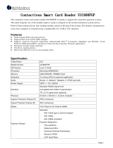
3. VP5300M Specifications
Physical
VP5300M Reader
163mm from back of mounting surface x 65mm flange width x
27.5 mm flange height (LxWxH)
NFC Antenna Bezel
65mm x 54mm x 14.5mm (LxWxH), not counting 15.5mm-deep
M4 studs that protrude from the back of the unit
Structure Material
Plastic bezel, PC UL 94V-0
Housing Color
Black
Weight
0.51 kg without SAM board
Bezel
Plastic bezel with texture
Electrical
Voltage Requirement
12V DC (minimum) recommended to 24V maximum
Environmental
Operating Temperature
-0° C to 50° C (32° F to 122° F)
Storage Temperature
-20° C to 70° C (-4° F to 158° F)
Operating Humidity
10% to 95% non-condensing
Storage Humidity
10% to 95% non-condensing
Transit Humidity
5% to 95% non-condensing
Operating Environment
Water resistant for indoor use
IK Rating
IK07
IP Rating
IP42
ESD (Device)2
Air discharge ±15kV (Discharge at Front Bezel Only)
Contact discharge ±8kV
Impact Resistance
The front face is impact resistant to IK07 rating
Ingress Resistance
The front face meets IP42 rating
Reliability
Magnetic Head
600,000 cycles minimum
Chassis, card slot
600,000 cycles minimum
Smartcard contact block
600,000 cycles minimum
Bezel and gate
600,000 cycles minimum
2 Note: Cables and connectors must be fully isolated with insulating material to prevent ESD discharge.

ID TECH VP5300M Integration Manual
Page | 10
Physical
Motorized mechanism
600,000 cycles minimum
MTBF
Over 100,000 hours
Receiver Subcarrier
Data
ISO 14443-2 Type A/ISO 14443-2 Type B:
ISO 18092
Typical Read Range
0~4cm(0~1.5 inches)

ID TECH VP5300M Integration Manual
Page | 11
4. VP5300M 3-View Drawing

ID TECH VP5300M Integration Manual
Page | 12

ID TECH VP5300M Integration Manual
Page | 13
5. NFC Antenna 3-View
Antenna mounting details:

ID TECH VP5300M Integration Manual
Page | 14
6. VP5300M Installation
This section provides information on how to install the VP5300M in an enclosure.
Note that the unit may be installed edgewise (vertically), or in a horizontal manner. It can also be
bolted to or custom-mounted flush with a surface. In the latter case, make sure to allow a 3mm
(minimum) cutout clearance around the edge of the metal face flange (assuming the enclosure is
metallic) to maintain good NFC performance. Do not tightly flush-mount the unit to a metal
enclosure. Test NFC performance thoroughly to be sure no interference or signal attenuation occurs.
6.1. Parts List
Verify that you have the following hardware for installing the VP5300M:
• IDM-101: VP5300M; Ethernet, No SAM, JIS; No conformal coating; Production Unit; No
custom features.
• (Optional) ViVOpay 5300M NFC Antenna P/N ID-80152002-003. You will need this item and
its cable (P/N 80152235-001 or 80152236-001) to use VP5300M’s contactless (NFC)
capabilities.
• USB cable P/N 80171201-001, or RS-232 cable P/N 80171203-001.
• Power supply P/N AC0005R-12 with cable 80171204-001.
6.2. Installing the Reader
Refer to the VP5300M 3-view drawing. Verify that power cords can physically reach the unit. Then
proceed to:
• Locate, mark, and drill holes for the mounting points of the unit.
• Secure the unit to the enclosure with bolts or screws of appropriate depth. Note that the anti-
tamper nubs, located on the unit's left side, must be depressed when the unit is mounted.
6.2.1. Protective Plastic Film
Note that the VP5300M comes with protective plastic film covering printed circuit boards and other
sensitive components; keep this protective film on the device during and after installation to ensure it
functions as expected.

ID TECH VP5300M Integration Manual
Page | 15
6.3. Mounting the VP5300M External NFC Antenna
Refer to the VP5300M Antenna 3-view drawing. If you are using the VP5300M’s contactless
capability, you will need to install the optional NFC antenna and its cabling.
Use the following instructions to mount the antenna on the exterior of a kiosk.
Note: It is recommended that you experiment with and verify the orientation of the NFC Antenna
before marking and drilling mounting holes, ensuring that the antenna is far enough away from the
main body of the VP5300M so that insertion of a "tap card" in the unit's contact-EMV slot doesn't
trigger an unwanted NFC interaction.
Important: Mark holes in such a way as to ensure that the ViVOpay NFC Antenna is oriented with the
LEDs at the top.
1. Locate and mark the four 4.5 mm (3/16 inch) mounting holes.
2. Locate and mark two 14.0 mm (0.551 inches) access holes (used for connecting the
antenna barrel connector and the LED power and data cable to the unit. Notice that these
holes are located off-center toward the top of the unit.
3. Drill the four 4.5 mm (3/16 inch) mounting holes.

ID TECH VP5300M Integration Manual
Page | 16
4. Drill the two access holes (14.0 mm, 0.551 inch) holes using a 35/64 drill bit.
5. Use the nuts that are supplied with the unit (in plastic bag).
6. Route the end of the cable (80152235-001) with the RJ-45 connector through the
matching 14.0 mm (0.551 inch) hole into the kiosk. Make sure that the front of the
antenna will be properly oriented (not upside down) on the kiosk before inserting the four
screws into the mounting holes.
7. Align the four threaded posts with their mounting holes and attach the ViVOpay NFC
Antenna to the mounting surface. Make sure that the cable is not pinched, rubbing, or
binding.

ID TECH VP5300M Integration Manual
Page | 17
8. Use the four nuts to secure the ViVOpay NFC Antenna to the surface of the kiosk. Make
sure to tighten the nuts securely so that the antenna does not move freely on the outside
surface of the kiosk.
Note: Tighten the nuts to 5-7 in/lbs. for a good weather-tight seal.
9. Attach the end of the cable with the SMB barrel connector through the right 14.0 mm
(0.551 inch) hole and secure it to its socket on the back of the antenna. The SMB
connector pushes onto the socket.
10. Attach the RJ-45 connector (male) coming from the ViVOpay NFC Antenna to the RJ-45
receptacle (female) on the 80152236-001 cable.

ID TECH VP5300M Integration Manual
Page | 18
6.3.1. Flush-Mounting the Antenna
The antenna’s RF field is sensitive to the proximity of metal. There are three options when flush-
mounting the antenna in a metal surface or bezel:
1. Mount with the RF emitting surface of the antenna at least 1cm forward of any metal.
2. Mount with the RF emitting surface of the antenna at least 1cm behind any metal. Note: this
reduces the antenna’s effective range.
3. Mount flush with the metal but allow a minimum of 1cm spacing between the antenna and
the metal.
In all three cases, make sure to test the antenna mounting before engaging in a production-ready
installation.
6.4. VP5300M Connectors
#
Description
Cable
1
SAM slot
Additional SAM slot (optional)
2
USB port
80171201-001, 4-pin USB cable
3
Antenna
80152236-001, connect to NFC antenna (ID-80152002-003)
4
Power
80171204-001, 2-pin power cable, with adaptor AC0005R-12
5
PINPAD
80141220-001, L100 cable
6
RS-232
80171203-001, 9-pin RS-232 cable
7
Ethernet
RJ-45 Ethernet cable (optional)

ID TECH VP5300M Integration Manual
Page | 19
6.5. Attaching the Cables from the Antenna to the VP5300M
1. Attach the SMB barrel end of the cable (80152236-001) from the antenna to the SMB
post of the VP5300M. The connector slides on.
2. Attach the 8-pin end of the cable (80152235-001) from the antenna to the VP5300M.
6.6. Connecting to Power
The VP5300M is powered through the power input connector.
1. Connect the 12V DC power supply (P/N AC0005R-12) with cable 80171204-001 to the
receptacle on the bottom side of unit.
2. Plug the unit in to an AC outlet and verify that the VP5300M lights up.
Note: The VP5300M requires a power supply whether connected by RS-232 or USB.

ID TECH VP5300M Integration Manual
Page | 20
6.7. Connecting to the Data Port
Use 9-pin JST P/N PHR-9 (or equivalent) for the RS232 connector or 5-pin JST P/N PHR-5 (or
equivalent) for the USB connector. See diagrams below for RS-232 or USB, as appropriate.
6.8. VP5300M External Cable Pin Assignments: RS-232
6.9. VP5300M External Cable Pin Assignments: USB
/