Page is loading ...

GW-MOD
COMMERCIAL AIR CONDITIONERS SDV5


1 Safety Precautions .................................... 1
2 Overview ................................................... 2
2.1 Gateway Interface ............................................... 2
2.2 System Architecture ............................................ 3
2.3 Function Code for Commands............................. 4
2.4 Error Response ................................................... 4
3 Using the Product...................................... 5
3.1 Default IP Address of Gateway ........................... 5
3.2 Gateway Settings ................................................ 6
3.3 View Air conditioner Information.......................... 7
3.4 Upper Computer Access ..................................... 9
3.5 Mapping Table Addressing.................................. 9
3.6 Examples............................................................. 9
4 Restore Factory Settings......................... 16
Contents

1. Safety Precautions
6
7
Get your distributor or a professional to install the product.
Read the safety precautions carefully prior to installation.
Make sure you observe the important safety precautions provided below.
Meanings of marks:
Icons
Once the installation work is completed, test to verify that the device is operating normally, and
hand over the manual to the customer for safekeeping.
Caution: Improper handling may lead to personal injury or material loss.
Warning: Improper handling may lead to death or serious injury.
The product, and its Operation and Installation Manual describes the following content,
including how to handle the product, prevent harm to others and prevent property losses, as
well as how to use the product correctly and safely. Read the following carefully and make
sure you understand the content (identifiers and marks), and observe the below
precautions.
Do not install the product to where there is a danger of flammable gas leakages. Any
leakage within the vicinity of the device may cause a fire.
Get your distributor or a professional to install the product. The installation
personnel must be equipped with the professional knowledge. When you
install on your own, any mistake you made during the operations may lead
to a fire, electric shock, or injury.
Do not use combustible paints to spray directly on the data converter as this
may cause a fire.
Do not handle the product with wet hands, and do not let water seeps into
the device, as this will cause electric shocks.
Warning
!
!
!
!
Caution
Icon
Warning
Using
Warning
Name
Prohibited. Specific information about the prohibited item is described within the icons or
in the form of graphics or text next to where the symbol is located.
Mandatory. Specific information about the mandatory item is described within the icons
or in the form of graphics or text next to where the symbol is located.
Commissioned
installation
Prohibited
Prohibited
Non-professionals may not install the equipment properly which may in turn lead to
electric shock or fire.
Caution
!
1
[Note] The "harm" means that the affected party does not need to be admitted to hospital or
require long-term treatment. This generally refers to wounds, scalds, or electric shocks.
Material losses refer to property and material losses.

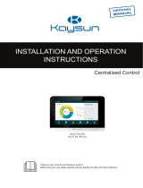
2. Overview
Figure 1
2-1 Gateway Interface
No. Item
485 indicator Indicates if the 485 communication is normal.
IP indicator Indicator for IP-based communications.
POWER indicator Power indicator.
A1B1E port 485 port to connect to the VRF air conditioning system.
A2B2E port
485 port to connect to an upper computer system that
supports the Modbus/RTU protocol.
DC 5V power interface.
RESET button.
WAN port Connecting to a switch through an RJ45 cable, to
access the built-in Web page of the gateway, or use
the Modbus/TCP protocol to access the gateway.
Description
① ② ③
④ ⑤ ⑥ ⑦ ⑧
2
POWER
RESET
①
②
③
⑤
⑥
⑦
⑧
④

2. Overview
2-2 System Architecture
The gateway only supports V6 outdoor air conditioning unit (for indoor units (IDUs),
please consult Technical Support). The IDU/ODU addresses for the air conditioning
unit cannot be reset once the unit is connected. Up to 64 indoor units and 4 outdoor
units in the same refrigerant system can be connected. When there is a change in the
network address of the ODU, and change in IDU address, you need to reboot the
gateway.
The upper computer system accesses the gateway using two methods: one is based
on the Modbus/RTU protocol through the 485 interface, as shown in ; another is
through the Modbus/TCP protocol, as shown in .
Figure 2 Modbus gateway system architecture diagram
*Please check with Technical Support on the applicable outdoor and indoor unit
models as well as the functions.
7
3

2. Overview
The master device sends a request and waits for a response from the slave
device. The slave device will respond normally if there is no error. If there is a
data verification error, the slave device will not respond. When there is an error
(except for verification error) in the data sent by the master device, the slave
device will respond with the error code.
Function Code Function Name Function
Read Discrete Input Read
Code Name Meaning
Invalid function
code
Slave unit does not support the
function code it has received.
Invalid data
address
Slave unit does not support the data
address it has received.
Invalid data Slave unit does not support the data
value it has received.
Slave unit
is busy
The slave unit is busy working on a
long command, and the master unit
needs to send the message when the
slave unit is idle.
Read Holding Register Read
Read Input Register Read
Write Single Register Write
Write Holding Register Write
2-4 Error Response
2-3 Function Code for Commands
0x01
0x02
0x03
0x06
4
0x02
0x03
0x04
0x06
0x10

3. Using the Product
7
3-1 Default IP Address of Gateway
The default IP address of the gateway is 192.168.1.200. The IP address of
the upper computer must be on the same network segment as the gateway,
that is, 192.168.1.xx (xx: 2~254). After the upper computer has been
configured with a static IP address, access the embedded web page to
change the IP address of the gateway as required.
To configure the static IP address on the upper computer: Open the protocol
property dialogue box to configure the IP address and subnet mask, such as
192.168.1.211 as the IP address and 255.255.255.0 as the subnet mask.
Then, click "OK", as shown below:
Figure 3
5

3. Using the Product
3-2 Gateway Settings
Open the browser, and enter "http://192.168.1.200" into the address bar to go
to the Web page of the gateway. Select "Settings". The following page is
displayed:
Once you have modified the corresponding parameter, click "Apply Setting". To view the
updated settings, click "Get Setting". After the change to settings, the Modbus gateway will
automatically restart, and the network will be disconnected, and then reconnected again.
Figure 4
The parameters in the settings are as follows:
Parameter Description
IP Address
Modbus
Address
Gateway device number that is used to distinguish multiple
Modbus gateways in the same segment. Addresses cannot
be repeated.
Modbus
Communication
Settings
Baud rate: Default is 9600;
Parity bit: Default is no parity check;
Stop bit: Default is bit 1.
IP address of the current Modbus gateway. IP addresses of
multiple Modbus gateways cannot be repeated.
Subnet Mask
Default: 255.255.255.0
Gateway
Gateway address of the local router
6

3. Using the Product
7
3-3 View Air conditioner Information
Select "Discrete inputs" or "Input register" in the Web page to view the air
conditioner information.
Select "Discrete inputs". In the displayed page as shown in the following
figure, click the address code of the IDU or ODU. The operating information
of the unit is displayed correspondingly. The red box shows the device that is
currently selected.
When you choose discrete inputs, you will get the following page. For
example, the address, "10369", represents the ON/OFF state of the IDU at
address 46. in the figure indicates the device is ON. Refer to the Address
Mapping Table for the VRF Modbus Gateway for specific details about the
parameters.
In the functional column of the input register, select an IDU to view relevant
information. Refer to the Address Mapping Table for the VRF Modbus
Gateway for details on the parameters shown in the list. For example, column
1 in the table below shows the address, column 2 shows the parameter
details, and column 3 is the parameter value, where an entry like 25/0019
means that 25 is decimal, and 0019 is hexadecimal.
Figure 5 Discrete inputs
7

3. Using the Product
Figure 6 Input Register
Figure 7 ODU information
Select Outlet#0, Outlet#1, Outlet#2, Outlet#3 at the lower right corner to go to
the parameter display page of the IDU. #0, #1, #2, and #3 represent four
ODUs (one master unit and three slave units) that belong to the same
refrigerant system. When ODUs from many refrigerant systems are
connected, only information about the ODU in the refrigerant system with the
lowest address will be shown. You need to restart the gateway if the ODU
address changes. For example, if the ODUs from refrigerant systems 2 and 6
are connected at the same time, then the gateway will read information about
the ODU from refrigerant system 2.
8

3. Using the Product
7
3-4 Upper Computer Access
The upper computer system can communicate with the gateway using either
Modbus/TCP protocol or Modbus/RTU. Refer to Figure 2 and Figure 3 for
information on the specific wiring.
3-5 Mapping Table Addressing
The register address in the mapping table uses a PLC address. The protocol
address is used during the actual communication, and the relationships
between the protocol address and the PLC address are as follows:
1) Discrete input register: Protocol address = Register address (PLC) - 10001
2) Input register: Protocol address = Register address (PLC) - 30001
3) Holding register: Protocol address = Register address (PLC) - 40001
3-6 Examples
A. Modbus/RTU data frame description:
Request/Response:
1) 0x02 Read Discrete Input
Suppose that the register address data in IDU0 is 10001~10003:
Start address = Register address - 10001
Actual address of 10001~10003 in IDU0 is 0~2.
Request message: 01 02 00 00 00 03 38 0B
Response message: 01 02 01 05 61 8B
Device Address
Error Check and
Correction
Function Code Data
1 byte 1 byte N bytes 2 bytes
9

3. Using the Product
Request Message Response Message
Domain Name (hexadecimal) Domain Name (hexadecimal)
Device Address Device Address
Function Code Function Code
Higher byte of start
address
Number of bytes
Lower byte of start
address
Input status 7-0
Higher byte of
number of discrete
inputs
Higher byte of
verification code
Lower byte of
number of discrete
inputs
Lower byte of
verification code
Higher byte of
verification code
Lower byte of
verification code
05 is the byte in the response message that reflects the input status with the
corresponding binary of 00000101, and the 0~2 address data is 101
respectively. Check the address mapping table which shows that the unit
power status is 1, error status is 0, and online status is 1.
2) 0x03 Read Holding Register
Suppose that the register address data in IDU0 is 40003~40005:
Start address = (Register address - 40000) - 1
Actual address of 40003~40005 in IDU0 is 2~4.
Request message: 01 03 00 02 00 03 A4 0B
Response message: 01 03 06 00 01 00 03 00 14 EC BA
01 01
02 02
00 01
00 05
00 61
03 8B
38
0B
10

3. Using the Product
Request Message Response Message
Domain Name (hexadecimal) Domain Name (hexadecimal)
Device Address Device Address
Function Code Function Code
Higher byte of start
address
Number of bytes
Lower byte of start
address
Higher byte of
holding register 1
Higher byte of number
of input registers
Lower byte of
holding register 1
Lower byte of number
of input registers
Higher byte of
holding register 2
Lower byte of
holding register 2
Higher byte of
holding register 3
Higher byte of
verification code
Lower byte of
verification code
Lower byte of
holding register 3
Higher byte of
verification code
Lower byte of
verification code
3) 0x04 Read Input Register
Suppose that the register address data in IDU0 is 30001~30008:
Start address = Register address - 30001
Actual address of 30001~30008 in IDU0 is 0~7.
Request message: 01 04 00 00 00 08 F1 CC
Response message: 01 04 10 00 02 00 0C 00 1A 00 00 00 EC 00 00 00 00
00 00 9E 37
7
01 01
03 03
00 06
02 00
00 01
03 00
03
00
A4
0B
14
EC
BA
11

3. Using the Product
Request Message Response Message
Domain Name (hexadecimal) Domain Name (hexadecimal)
Device Address Device Address
Function Code Function Code
Higher byte of start address Number of bytes
Lower byte of start address
Higher byte of input register 1
Higher byte of number of input
registers
Lower byte of input register 1
Lower byte of number of input
registers
Higher byte of input register 2
Lower byte of input register 2
Higher byte of input register 3
Higher byte of verification code
Lower byte of verification code
Lower byte of input register 3
Higher byte of input register 4
Lower byte of input register 4
Higher byte of input register 5
Lower byte of input register 5
Higher byte of input register 6
Lower byte of input register 6
Higher byte of input register 7
Lower byte of input register 7
Higher byte of input register 8
Lower byte of input register 8
Higher byte of verification code
Lower byte of verification code
12
01 01
04 04
00 10
00 00
00 02
08 00
0C
00
F1
CC
1A
00
00
00
EC
00
00
00
00
00
00
9E
37

3. Using the Product
4) 0x06 Write Single Register
For example, if the register address for all the devices in group control is
40001, and the parameter value of group control is set to 2.
Start address = Register address - 400001
The initial address of 40001 for the group control is 0.
Request message: 01 06 00 00 00 02 08 0B
Response message: 01 06 00 00 00 02 08 0B
Request Message Response Message
Domain Name (hexadecimal) Domain Name (hexadecimal)
Device Address Device Address
Function Code Function Code
Higher byte of
register address
Higher byte of
output address
Lower byte of
register address
Lower byte of
output address
Higher byte of
register value
Higher byte of
output value
Lower byte of
register value
Lower byte of
output value
Higher byte of
verification code
Higher byte of
verification code
Lower byte of
verification code
Lower byte of
verification code
7
01 01
06 06
00 00
00 00
00 00
02 02
08 08
0B 0B
13

3. Using the Product
5) 0x10 Write Holding Register
For
example, controls for the mode, fan speed and temperature
setting in
IDU0 are cool, fan speed 3, and 20°C respectively, and the corresponding
register addresses are 40003~40005.
Start address = Register address - 40001
Actual start address of 40003~40005 is 2~4.
Request message: 01 10 00 02 00 03 06 00 02 00 03 00 14 CE 85
Response message: 01 10 00 02 00 03 21 C8
Request Message Response Message
Domain Name (hexadecimal) Domain Name (hexadecimal)
Device Address Device Address
Function Code Function Code
Higher byte of start address Higher byte of start address
Lower byte of start address Lower byte of start address
Higher byte of register number Higher byte of register number
Lower byte of register number Lower byte of register number
Number of bytes Higher byte of verification code
Higher byte of register value Lower byte of verification code
Lower byte of register value
Higher byte of register value
Lower byte of register value
Higher byte of register value
Lower byte of register value
Higher byte of verification code
Lower byte of verification code
01 01
10 10
00 00
02 02
00 00
03 03
06 21
00 C8
02
00
03
00
14
CE
85
14

3. Using the Product
B. Modbus/TCP data frame description:
MBAP packet header
Item processing
identifier
2 bytes
Protocol
identifier
2 bytes
Length
2 bytes
Unit identifier
1 byte
Function code
1 byte
Data
1 byte
1) 0x02 Read Discrete Input
Suppose that the register address data in IDU0 is 10001~10003:
Request Message: C9 ED 00 00 00 06 01 02 00 00 00 03
Request Message: C9 ED 00 00 00 04 01 02 01 05
2) 0x03 Read Holding Register
Suppose that the register address data in IDU0 is 40003~40005:
Request Message: CA A9 00 00 00 06 01 03 00 02 00 03
Request Message: CA A9 00 00 00 09 01 03 06 00 02 00 03 00 14
3) 0x04 Read Input Register
For example, reading the register address data in IDU0 as 30001~30008:
Request Message: CB 0E 00 00 00 06 01 04 00 00 00 08
Request Message: CB 0E 00 00 00
13 01 04 10 00 02 00 0C 00 1A 00 00
00
EC 00 00 00 00 00 00
4) 0x06 Write Single Register
For
example, if the register address for all the devices in group control
is
40001, and the parameter value of group control is set to 2:
Request Message: CC 47 00 00 00 06 01 06 00 00 00 02
Response Message: CC 47 00 00 00 06 01 06 00 00 00 02
5) 0x10 Write Holding Register
For
example, controls for the mode, fan speed and temperature setting
in
IDU0 are cool, fan speed 3, and 20°C respectively, and the corresponding
register addresses are 40003~40005:
Request Message: CB EC 00 00 00 0D 01 10 00 02 00 03 06 00 02 00 03 00
14
Response Message: CB EC 00 00 00 06 01 10 00 02 00 03
7
15

4. Restore Factory Settings
Press and hold the Reset key on the gateway, and then power on the gateway
and release the button after 2 seconds to restore the system to factory
settings.
16

!
"#$%#
!$"$$%
# #%&#'!#$
##$#"$
%"# #%
+)
*;((;%
6'<($#*%
;163;+
&
%' %
59%
*(
*;(%%%
"#<4
26088&
:
=(;*)
*;(%%%
"#<4
26088&
:
%.><08?886880?4
@.><084<64A860<
%'%
B'%
/