Page is loading ...

FULL DC INVERTER SYSTEMS
FASCIA PANEL SDV5-XXP
COMMERCIAL AIR CONDITIONERS SDV5

I. Precautions
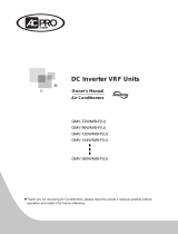
II. Description of Panel Parts
III. Applicable Models
Installation methods and other precautions
CauseDescription
Digital display
tube
Defrosting
indicator
Infrared
human sensor
Running
indicator
Air outlet
panel
Display box
Refrigerant
pipe
Drainage
pipe
Humidification
tube
Upper and lower louvers (automatic)
Embedded left and right louvers
(automatic)
IV. List of Components
Applicable model
Air outlet panel 01 02 03
A (ceiling opening width)
B Ceiling
opening height
E
C
Air outlet panel
Indoor air
outlet flange
Ceiling
D
≥ 80 (distance from the ceiling to the
front of the unit body)
≥35 (distance
from the opening
hole to the top
of the ceiling)
Indoor air
outlet flange
IDU electric control board
Ceiling
Figure 2
2. To install the panel, the reserved opening hole sizes for the ceiling are shown in Figure 2,
Table 2, and Table 3.
3. Install the air outlet panel.
3.1 Installation method 1: Directly fix the air outlet panel onto the reinforced wooden support of the ceiling
with flat head screws.
1 pcs
1 pcs
Instruction
Air outlet panel Cross recessed head screw
Figure 3
3.1.1 Position of the screw holes on the air outlet panel:
705
925
1145
Table 1 (Unit: mm)
Table 2 (Unit: mm)
Table 3 (Unit: mm)
Model A
01
02
03
650 to 660 150 to 156 0 to 10 0 to 10 0 to 9
870 to 880 150 to 156 0 to 10 0 to 10 0 to 9
1090 to 1100 150 to 156 0 to 10 0 to 10 0 to 9
Model A B
01 series Panel
02 series Panel
03 series Panel
DC E
507
727
947
B
646
866
1086
CD F G H I J K L M N
Temperature and error display
Remote control reception and
infrared human sensor
E
41.5
75.5
107
192
205
268
199.5
165
229
/
238
235
42
42
42
94
81.5
113
250.5
240
318.5
78
240
319
/
81.5
113
3
4
4
4
5
5
Timer
indicator
Remote control
receiving window
The non-humidifying unit is not equipped with humidification
tubes and the corresponding frames
Models
(At this point, the panel frame is over 10 mm
away from the air outlet of the unit.
The distance threshold is 56 mm, but the panel
needs to directly face and be inserted into the air
outlet of the unit.)
F
J
GH
I
E
740 350 193.5 64.5 17
960 350 193.5 64.5 17
1178 350 193.5 64.5 17
Model F G
Applicable IDU (01 series)
Applicable IDU (02 series)
Applicable IDU (03 series)
I
H Humidifier
I Humidifier
J Humidifier
J
62
62
62
29
29
29
H
69.5
69.5
69.5
210
Figure 1
V. Installing the Panel
1. Structure and external dimensions (see Figure 1 and Table 1)
6 pcs
Version: 16123000003013 V.A
Thank you very much for purchasing our product.
Before using your unit, please read this manual carefully and keep it for future reference.
Ask a professional installation company to install the air conditioner, so as to ensure the
installation quality.
To prevent condensation, the joints of the panel need to be sealed and wrapped with
protection sponge, and metal parts such as screws shall not be exposed.
Ensure that the ceiling opening hole sizes are accurate.
The following phenomena are normal and do not indicate a fault.
Running indicator: it is on when the power is turned on, off when the power is turned off, and
flashes slowly while in standby mode.
Defrosting indicator: When defrosting or anti-cold wind protection is enabled, the indicator is on.
Timer indicator: When the timing function is on, the indicator is on.
Digital display: In Cool or Heat mode, the digital display shows the set temperature. In Fan mode,
it displays the indoor temperature. In separate humidification mode, it displays the set humidity.
When an error occurs, it displays the error code (see the IDU manual for the error definitions).
When the above indicators are set to be always on via the remote controller or wired controller,
operating indicator and digital display will be steady on, the timer indicator will be steady on during
the timed period, and defrosting indicator will be on when the unit defrosts. When the above
indicators are set to be always off via the remote controller or wired controller, operating indicator,
digital display and timer indicator will be on after the corresponding instruction is received, and will
be off after 15s, and defrosting indicator will not be lit when the unit runs in defrost mode.
Confirm the ceiling opening position to ensure that the distance from the ceiling to the front
of the unit body is ≥80 mm;
Confirm the ceiling opening position to ensure that distance from the opening hole to the
top of the ceiling is ≥35 mm;
Check whether the ceiling opening size, and the position of the air outlet of the IDU and the
ceiling opening meet the requirements specified in Figure 2.
Check whether the strength of the ceiling for panel installation is appropriate. If the strength
is weak, reinforce the openings to achieve sufficient installation strength.
Check whether the IDU is parallel to the ceiling.
White mist is discharged from
the panel
The panel generates low
noises
Condensation may occur on
the surface of the panel and
water may drip
Avoid People/Blow on People
is unresponsive
Louver is perpendicular to the
panel and it is impossible to
adjust louver operating angles
After clicking Light Off, the
panel indicator is still on
(1) Due to high humidity and the temperature difference between the air inlet and outlet, cold air may form
white mist.
(2) When the mode is switched from defrosting to heating, moisture may be discharged in the form of mist.
(3) When the humidifier operates, the steam may form mist after meeting cold air and then be discharged.
(1) Squeak from natural expansion or contraction of plastic parts.
(2) The louvers may generate low friction sound when they are rotating.
(1) When the unit operates in "cooling" mode in a relatively humid environment (relative humidity
higher than 80%), condensation may occur on the surface of the panel and water may drip.
(2) When the humidifier operates too long, condensation may occur on the surface of the panel and
water may drip.
(1) The panel is not equipped with an infrared human sensor.
(2) Wearing thick clothes, other heat sources present in the room, any objects blocking the infrared
human sensor or falling within the dead zone of the infrared human sensor, may affect the accuracy
and actual effect of smart eye detection.
In a mode other than heating, the panel may automatically adjust the louver angle to ensure the best
effect of humidification. At this time, the lover angle cannot be customized.
After pressing the OFF button, the panel indicator will automatically turn off after 15s without
operation, please wait patiently.
192
76141
147 19
14
14
71
6.5
6.5
17
A
B
F
C 19
G
M X Ø 3.2
N X Ø 5.5
HIJKL
E D
150
CAUTION
Make panel fixing screws symmetrically distributed at the
upper and lower sides. The 01 series panel has 2 holes each
on the top and bottom, and the 02 and 03 series panels have
3 holes each on the top and bottom. All panels have 1 hidden
hole on the left, right, top and bottom, which can be selected
according to actual needs.
SDV5-01P/02P/03P has neither human body sensing function nor Wi-Fi.
.
MODELS: SDV5-01P, SDV5-02P, SDV5-03P
INSTALLATION MANUAL OF FASCIA PANEL
DAP IDU series: 17-36 DAP IDU series: 45-56 DAP IDU series: 71
SDV5-01P/02P/03P series panels areapplicable for small-sized VRF IDUs;
Note: The
upper
table lists the models of
DA
P
series duct IDUs that support arc-fin
evaporator.

4. Open the IDU electric control box cover and connect the panel cable to the IDU electric
control part (refer to Figure 8).
M X Ø 3.2
Ensure that there are no gaps between the IDU and the air outlet panel, and between the
air outlet panel and the ceiling. Otherwise, check whether the screws are fastened tightly
during installation.
If there are still gaps after all screws are tightened, remove the air outlet panel, adjust the
distance from the air outlet of the IDU to the ceiling, and then install the air outlet panel
again.
If the IDU is too far away from the ceiling or there is a level difference between the IDU and
the ceiling opening, you can make and connect the corresponding soft air duct as required.
CAUTION
Make sure to use flat head screws to fix the panel onto the ceiling to prevent the screws
from skewing or loosening, and the screw caps must be completely embedded in the
corresponding concave pits; otherwise, the louver may interfere with the screw cap,
causing the louver not to operate normally. In addition, check whether the louver is
normally reset.
Make sure to add reinforced wooden support for the air outlet at the ceiling opening hole
of the panel. The height of the wooden support is shown in Figure 4.
When fixing the panel, you can press the top louver and move the bottom louver with
moderate strength to release the lock, so as to easily fix the flat head screws with tools;
otherwise, the louvers may permanently be deformed. The lock must be reset after it is
released, otherwise, it may cause abnormality, as shown in Figure 5.
Make sure to add reinforced wooden support for the air outlet; otherwise, unsecured fixing
may result in hidden danger.
If the IDU is too far away from the ceiling or there is a level difference between the IDU
and the ceiling opening, you can make a corresponding soft air duct or insulation air duct
to avoid cold or heat leakage.
CAUTION
VI. Confirmation after Installation
VII. Cleaning of the Air Outlet Panel
IDU
No gap
Ceiling
Air outlet
panel
6. Check whether the left and right gaps of the 4 top and bottom louvers are even;
IDU main control board
CN30
Red Four
Gap on the left
Gap on the right
Figure 5
Figure 6
3.1.3 To easily fix the screws, you can press and move the top and bottom louvers with moderate strength
to release the lock;
3.2.1 Poke through the corresponding holes of the sponge covering the Mxφ3.2 screw holes on the upper
and lower sides of the following panel;
3.2.2 Insert the panel into the air outlet of the IDU until it is
propped, and use screws to fix the panel onto the air
outlet of the IDU. Note that the panel needs to be
held while fixing to prevent it from falling.
3.2.3 After installation, check whether the screws are
fixed according to the panel holes. If not, it may
hinder the left and right swing of the louvers.
3.2 Installation method 2: Directly fix the air outlet panel onto the air outlet of the IDU, which is only
applicable for nude packing.
Press the upper louvers
by hand and fix the
upper screws
Move the lower
louvers by hand and
fix the lower screws
Push aside the buckle by
hand and fix the upper
and lower screws
Figure 8
Figure 7
CN1
CN30
CN4
White
Five
Black Four
White
Five
Red
Five
CN2 CN3
M M M
Human
sensor
Distance from the screw hole to the outer surface of the panel: 17 mm
Plasterboard
thickness≥6mm
Wooden support
height≥30mm
Flat head
screws
Plasterboard
Reinforcing wooden
frame
Except for the
circumstance where
the panel is directly
inserted in the IDU's
air outlet, in other
circumstances
canvas duct is
required for
connection to
prevent air leakage.
Figure 4
Indoor air outlet
flange
Main control board
The jack no. of the IDUs with
humidifier is CN30, and the jack
no. of other IDUs may be different.
Shielded wire is fixed to the sheet
metal of the IDU with brass screws
Air outlet
panel
3.1.2 Fix the air outlet panel onto the ceiling.
Ceiling
5. Left and right louvers can automatically adjust within a range of angles.
Upper and lower louvers Left and right louvers
Precautions for wiring: Arrange professional personnel for wiring according to the wiring
diagram. Do not connect the cables with power on. Cable connection with power on or wrong
connection may burn the display box and cause personal injury.
Whether there is a gap between the air
outlet panel and the ceiling.
Whether there is a gap between the air
outlet panel and the flange.
Check whether there is a gap between the
flange and the IDU.
Note: The gap (if any) may lead to air
leakage, condensation, abnormal sound and
other problems.
1. Wipe the air outlet panel with a dry cloth.
2. If the air outlet panel is extremely dirty, wipe it with a cloth dipped in an aqueous solution of
neutral detergent.
Do not use gasoline, benzene, volatile agents, decontamination powder and liquid
insecticides. Otherwise, the air outlet or panel may de-color or deform.
Do not expose the inside of the IDU to moisture, as it may result in electric shock or fire.
When cleaning the air guide louver with water, do not scrub it violently.

!
"#$% #
!$"$$%
# #%&#'!#$
##$#"$
%"# #%
-##:%
+)
*;((;%
6'<($#*%
;163;+
&
%' %
59%
*(
*;(%%%
"#<4
26088&
:
=(;*)
*;(%%%
"#<4
26088&
:
%.><08?886880?4
@.><084<64A860<
%'%
B'%
/