Page is loading ...

SL STRIP 10IP
LED LUMINAIRE

www.philips.com/showline
Version as of : 17th Sep 2015
SL S
T
R
I
P
1
0
I
P
U
s
e
r
’s M
a
n
u
a
l
2015 Vari-Lite.
Document Number: SL STRIP 10IP LED Luminaires User Manual

Installation and User's Manual
IMPORTANT INFORMATION
IMPORTANT INFORMATION
When using electrical equipment, basic safety precautions should always be followed including the following:
a. READ AND FOLLOW ALL SAFETY INSTRUCTIONS.
b. Do not mount near gas or electric heaters.
c. Equipment should be mounted in locations and at heights where it will not readily be subjected to
tampering by unauthorized personnel.
d. The use of accessory equipment not recommended by the manufacturer may cause an unsafe
condition.
e. Do not use this equipment for other than intended use.
f. Refer service to qualified personnel.
SAVE THESE INSTRUCTIONS.
WARNING: You must have access to a main circuit breaker or other power disconnect device before
installing any wiring. Be sure that power is disconnected by removing fuses or turning the main circuit
breaker off before installation. Installing the device with power on may expose you to dangerous
voltages and damage the device. A qualified electrician must perform this installation.
WARNING: Refer to national Electrical Code and local codes for cable specifications. Failure to use
proper cable can result in damage to equipment or danger to personnel.
WARNING: This equipment is intended for installation in accordance with the National Electric Code
and local regulations. It is also intended for installation in indoor applications only. Before any
electrical work is performed, disconnect power at the circuit breaker or remove the fuse to avoid
shock or damage to the control. It is recommended that a qualified electrician perform this installation.
Warnings and Notices
Additional Resources for DMX512
For more information on installing DMX512 control systems, the following publication is available for purchase
from the United States Institute for Theatre Technology (USITT), "Recommended Practice for DMX512: A Guide
for Users and
Installers
,
2
nd edition" (ISBN: 9780955703522). USITT Contact Information:
USITT
315 South Crouse Avenue, Suite 200
Syracuse, NY 13210-1844
Phone: 1.800.938.7488 or 1.315.463.6463
www.usitt.org
Showline Limited Two-Year Warranty
Showline offers a two-year limited warranty of its luminaires against defects in materials or workmanship from the
date of delivery. A copy of Showline two-year limited warranty containing specific terms and conditions can be
obtained by contacting your local Showline office.
SL STRIP 10 IP LED Luminaires

GENERAL INFORMATION
1
About this Manual
Included Items
The document provides installation and operation instructions for the following product:
SL STRIP 10 IP LED LUMINAIRE
Please read all instructions before installing or using this product. Retain this manual for future reference.
Additional product information and descriptions may be found on the product specification sheet.
AC Input cable (1750mm)
(For US, Canada and Latin America market only)
AC Input cable (1500mm)
(For International market only)
AC Output cable (1000mm)
(For International market only)
AC Output cable (1000mm)
(For US, Canada and Latin America market only)
DMX Input cable (1000mm)
DMX Input cable (1000mm)
DMX Output cable (1000mm)
DMX Output cable (1000mm)
North American Market
International Market
Installation and User's Manual
SL STRIP 10 IP LED Luminaires
Note: The SL STRIP 10 IP LED Luminaire is universal voltage 100 to 240 VAC (auto-ranging).
QuickStart Guide
Diffuser Lens Kit*
*
Note: Diffusers with 3 different beam
angles for options: 15 degree, 25 degree
and 11x38 degree
SL STRIP 10IP LED Luminaire
OR

MAIN FEATURES
2
MAIN FEATURES
01 pixel, 02 pixel, 05 pixel,10 pixel DMX Channel selection
10 built-in chase programs
0-255 dimming level
Standard DMX-512 and RDM protocol
01 Thru 99 Chase Speed adjustment
Power failure memory
LED display window-shows current activity and function state
SL STRIP 10 IP LED Luminaires
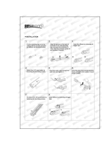
INSTALLATION
Wing screw(x2)
Trunnion Arm
(x2)
Installation and User's Manual
Trunnion Arm (x2)
Safety Cable Anchor Point
Hanging Application
SAFETY CABLE: Is sold
separately and recommended for
all hanging installations and may
be required by national and local
codes. Use the provided safety
cable anchor points to attach the
safety cable for this luminaire.
SL STRIP 10IP LED Luminaires are provided with Trunnion Arms. The user can tighten the wing screws manually. For
hanging applications it is recommended (and may be required by local and national safety codes) to use and install a safety
cable (sold separately). When hanging the fixture, be sure to leave enough space around the luminaire to allow proper,
uninterrupted air flow.
SL STRIP 10 IP LED Luminaires

POWER REQUIREMENTS
3
Installation and User's Manual
SL STRIP 10 IP LED Luminaires
Power Requirements
The SL STRIP 10IP LED Luminaire operates on AC input voltages from 100 to 240 VAC.
WARNING: This unit does not contain an ON/OFF switch. Always disconnect power input cable to completely remove power from unit
when not in use.
AC Power Operation
When connected to an AC source, the unit operates on 100 to 240 volts AC (+/- 10%, auto-ranging). The luminaire contains an auto-ranging power supply.
Each luminaire can draw up to 150 Watts.
The maximum amount of units that may be daisy-chained is (A) 6 units 100VAC (10 Amps) or (B) 16 units 240VAC (10 Amps) for
The maximum amount of units that may be daisy-chained is (A) 6 units 100VAC (10 Amps) for UL standard.
Europe Standard. Refer to Table1-1for detailed information at various voltages.
Note: For wiring of AC input connector, refer to Connecting SL STRIP 10IP LED Luminaires to AC Power.
Table 1-1: SL STRIP 10IP LED Luminaires Voltage vs. Current
WARNING: *These figures are based on the Maximum Allowable Input Current of 10 Amps (and the maximum power supply limit of 150
Watts). Do not overload circuits!
IMPORTANT AC POWER CONNECTION NOTES:
Connecting Power
Units can be powered in one of two ways:
D i r e c t connection to an AC power source using an AC input cable. For wiring of AC input connector, refer to Connecting SL STRIP 10IP
LED Luminaires to AC Power.
C o n n e ction from the AC output of another SL STRIP 10IP LED Luminaire. When using this method, it is very important not to
connect any other type of equipment.
Connecting SL STRIP 10IP LED Luminaires to AC Power
WARNING:
WARNING:
WARNING: Only connect other SL STRIP 10IP LED Luminaires to the AC Output (Thru) connector of a SL STRIP 10IP LED Luminaire.
Wh e n using the daisy-chain connection method, ONLY connect SL STRIP 10IP LED Luminaires to the AC Output Connection of other
SL STRIP 10IP LED Luminaires. DO NOT CONNECT OTHER TYPES OF LUMINAIRES OR DEVICES
Us e o nly use approved cable types.
Do n o t overload circuits!
Do n o t connect SL STRIP 10IP LED Luminaires to dimmed circuits.
Th e M AXIMUM allowable number of SL STRIP 10IP LED Luminaires which can be 'daisy chained' on one 10A power feed is listed in
Table 1-1. DO NOT EXCEED!
100 100
1.50
8
14
14
6 6
1.50
230
0.65
220
0.68
120
1.25
Voltage (AC) Voltage (AC)
Total Current (A) Total Current (A)
Max Connected
Max Connected
For European Standard For UL Standard
Table 2: AC Input Connections
Wire Color
Purpose
Table 2, AC Input Connections describes how to connect power to your SL STRIP 10 IP. Field wiring of the SL
STRIP 10 IP is straight forward. A total of 3 wires/conductors is supplied to the unit.
Brown
Blue
Yellow
Main/Line(100 to 240 VAC)
Neutral
Ground(Earth)
For European Market

LAYOUT OVERVIEW
4
Layout Overview
Rear Panel Overview
1. LCD Display
This multi-function display details all DMX Address, Chase , Program, Speed activity that pertains to the
current
operation mode of the unit.
2. Mode button
This button toggles the unit's operating mode between DMX, Chase and Manual mode.
5. Menu button
This button selects the different functions in DMX Mode, Chase Mode and Manual Mode.
3. UP button
This button increases the displayed value in the LED display.
4. Down Key
This button decreases the displayed value in the LED display.
6. AC Input Connector:
AC110-240V~50/60Hz, Max15A. Be sure to always connect to the proper voltage.
7.
RDM / DMX Input Connector
8.
9. AC Output Connector:
AC110-240V~50/60Hz, Max15A. This connector outputs the mains supply to the next unit.
POWE R THRU
(15A Ma x.)
110-2 40V~
50/6 0Hz
POWE R INPUT
(15A Ma x.)
110-2 40V~
50/6 0Hz
RDM/ DMX
OUTP UT
RDM/ DMX
INPU T
Made in China 中国制造
IP65
0.2m
o
40 C
SL STRIP 10IP
Mini mum saf ety dis tance t o flamm able ma teria ls: 0.2 m.
Dist ance de s écuri té mini male au x matér iaux in flamm ables : 0.2 m.
Minim um safet y dista nce from l ighte d objec ts: 0.5 m
Dist ance de s écuri té mini male de s objet s illum inés: 0 .5m
Maxi mum ope ratin g tempe ratur e of encl osure s urfac e is 60 °C
Tempér ature d e fonct ionne ment ma ximal e de la sur face de l 'ence inte es t de 60 °C
DO NOT STARE AT THE OPERATING LIGHT SOURCE
警告: 机器 在 接电 前请 参 阅安 装 ⼿册 ,使 ⽤ 带安 全 接地 的电
源插 座 ; 本机 器 有 电击 风 险 ,⾮ 专 业 ⼈ 员切 勿 私 ⾃打 开 机
壳, 维修 前 请先 切 断电 源。
POWE R INPU T(输⼊电压) : 110-24 0V~, 5 0/60H z;
POWE R CONS UMPTI ON(功耗): 1 50W Ma x.
CAUT ION / ATTEN TION:
RISK OF ELECTRIC SHOCK DO NOT OPEN
RISQUE DE CHOC ÉLECTRIQUE NE PAS OUVRIR
NOT FOR HOUSEHOLD USE.
IMPROPRE A L'USAGE DOMESTIQUE
DRY LOCATIONS
EMPLACEMENTS SECS
NOT FOR RESIDENTIAL / HOUSEHOLD USE
PAS POUR USAGE RÉSIDENTIEL / MÉNAGE
FOR S AFE TY IN STR UCTI ON AN D MOU NTI NG OP TION S
REF ER TO U SER M ANU AL
POU R INS TRU CTIO N DE S ECU RITE ET OP TION S DE
MON TAGE R ÉFÉ RER AU MAN UEL UT ILI SATE UR
MODE
MENUUP
DOWN
2
1
3
4
5
8 96 7
RDM / DMX Output Connector
Installation and User's Manual
SL STRIP 10 IP LED Luminaires
For North American Market
The luminaire is equipped with an IP rated connector and an AC Input cable is provided.

OPERATION MODES
5
OPERATION MODES
The SL STRIP 10IP LED Luminaire has three different operation modes.
Please follow illustrations below to operate the unit in your desired mode.
DMX Mode
Use this mode to use the unit as a DMX dimmer.
Set the unit control zones as 01 pixel, 02 pixel, 05 pixel,or 10 pixel.
Set the DMX Start Address, and the fixture behaviour without DMX input.
Mode
Parameter
Parameter Value
Function
DMX
Chase
Manual
Calibration
Address
Channel
DMX Fade
Program
Speed
Dimmer
Fade
R
G
B
W
001-512
8 Bit:1/2/5/10 pixel 16 Bit:1/2/5/10 pixel
OFF/ON
01-10
01-99
000-255
000-100
000-255
000-255
000-255
000-255
To set the initial DMX receiving address
To set the DMX Control Mode
To set the status of the fixture when there is no DMX input
To set the output intensity of the red
To set the output intensity of the green
To set the output intensity of the blue
Can be set as ON or OFF
To set the output intensity of the cool white
To select a built-in program
To set the speed level of the built-in Program
To set the intensity
To set the speed of the Fadetime(percentage)
SL STRIP 10IP DMX Mapping (RGBW 16 Bit Mode)
Red _ 9-10 - High Byte
Blue _ 9-10 - High Byte
Green _ 9-10 - High Byte
White _ 9-10 - High Byte
Red _ 9-10 - Low Byte
Blue _ 9-10 - Low Byte
Green _ 9-10 - Low Byte
White _ 9-10 - Low Byte
Installation and User's Manual
SL STRIP 10 IP LED Luminaires

SL STRIP 10IP DMX Mapping (RGBW 16 Bit Mode)
SL STRIP 10IP DMX Mapping (RGBW 8 Bit Mode)
OPERATION MODES
6
Red_1-10
Green_1-10
Blue_1-10
White_1-10
Installation and User's Manual
SL STRIP 10 IP LED Luminaires

Chase Mode:
The unit has 10 built-in chase programs.
Use this mode to select a built -in chase and edit the speed and fade
information.
Chase
Prog:01
MODE UP DOWN MENU
DMX Addr
Addr:512
DMX Ch
1 Pixel
DMX Bit
8 Bit
DMX Fade
Fade on
MODE UP DOWN MENU
MODE UP DOWN MENU
MODE UP DOWN MENU
MODE UP DOWN MENU
1. Setting the Chase Program:
1. Setting the DMX Address
4. Setting the DMX Channel
2. Setting the DMX Bit resolution
3. Setting DMX Fade On/OFF
Press the “MODE” button to activate the Chase Mode. Press the “MENU”
button to select and activate the“Chase Program” menu. The chase pattern is
displayed in the LCD as "Chase Prog " followed by the chase number. Press
the “UP” and “DOWN” button to select and activate the desired chase.
Press the “MODE’ button to select and activate the “DMX” menu.
Set the DMX address, DMX Bit, DMX Fade and DMX Channel. Press
the “MENU” button to select and enter the desired menu.
The DMX Address Mode is indicated by “DMX Addr” followed by three
digits 001~512. Press the "UP " and "DOWN" buttons to change the
DMX Address Value.
Press the “MENU” button to select and activate the “DMX Ch” menu.
Press the "UP " and "DOWN" buttons to change the DMX Channel
Value between 1 pixel, 2 pixels, 5 pixels and 10 pixels.
Press the “MENU” button to select and activate the “DMX Bit” menu.
Press the "UP " and "DOWN" buttons to change the DMX Bit Value
between 8 Bit and 16 Bit.
Press the “MENU” button to select and activate the “DMX Fade” menu. Press
the "UP " and "DOWN" buttons to set the DMX Fade on or off.
SETTING THE DMX ADDRESS
7
Installation and User's Manual
SL STRIP 10 IP LED Luminaires

Manual Mode:
Use this mode to manually set the Red, Green, Blue, and Cool White intensity.
Manual:
R:000
Manual:
G:255
Press “MODE” button to select and activate “Manual”
menu. In this menu, you can adjust the intensity of each color. Press
“MENU” button to toggle the color between R, G, B and W.
Press the "UP " and "DOWN" buttons to adjust the color intensity from
000 to 255.
MODE UP DOWN MENU
MODE UP DOWN MENU
2.
4. Chase Dimmer Menu:
3. Chase Fade Menu:
Press the "UP" and "DOWN " buttons to adjust the light output
intensity from 000 to 255. A value of 000 will give you the
minimum output intensity and a value of 255 will give you the
maximum output intensity.
Chase
Speed:01
Chase
Fade:000
Chase
Dimm:000
Chase
Dimm:255
Chase Speed Menu:
Press the “MENU’ button to select the “Chase Speed” menu.
In this menu, you can adjust the program chase speed.
Press the "UP " and "DOWN" buttons to adjust the chase speed from 01
to 99. A value of 99 will give you the fastest chase speed
(approx.1/10th of a second) . A value of 01 will give you the slowest
chase speed (once every 30 seconds).
Press the “MENU” button to select the “Chase Dimmer” menu.
In this menu, you can adjust the program light output.
Press the“MENU” button to select the“Chase Fade” menu.
In this menu, you can adjust the program fade speed.
MODE UP DOWN MENU
MODE UP DOWN MENU
MODE UP DOWN MENU
MODE UP DOWN MENU
Note: When the LCD backlight is off, pressing any button will activate the LCD display and show the current
operating temperature.
OPERATING MODE
8
Installation and User's Manual
SL STRIP 10 IP LED Luminaires
Press the "UP " and "DOWN" buttons to adjust the fade speed from 000
thru 100.

SL STRIP 10IP RDM Parameter IDs
The following tables outline and describe all the RDM parameters IDs associated with SL STRIP 10IP.
Table 1: SL STRIP 10IP RDM Parameter IDs
SL STRIP 10IP
SL STRIP 10IP
0x1000
Vari-Lite Asia
0x0105
RDM PARAMETER IDS
9
82H
Installation and User's Manual
SL STRIP 10 IP LED Luminaires

Table 1: SL STRIP 10IP RDM Parameter IDs
RDM PARAMETER IDS
10
Installation and User's Manual
SL STRIP 10 IP LED Luminaires

Table 2: SL STRIP 10IP Manufacturer Status IDs
Table 3: SL STRIP 10IP Manufacturer Specific PIDs
Manufacturer Defined Status IDs
Manufacturer Specific messages are in the range of 0x8000 —0xFFDF. Each Manufacturer-specific Status ID shall
have a unique meaning, which shall be consistent across all products having a given Manufacturer ID. See Table B-2,
ANSI E1.20-2010
Status Message ID
Value Data Value 1 Data Value 2
Status ID Description
8100H 00H 00H ALL OK
Manufacturer Specific PIDs
Manufacturer Defind PIDs range is 0x8000-0xffdf. See Table A-3, ANSI E1.20-2010
Get
Allowed
SET
Allowed
RDM Parameter
Id’s
TYPE UNIT PREFIX MIN MAX DEFAULT DESCRIPTION
Chase program
Chase Dimmer
DMX Fade on/off
Manual red
Manual green
Manual blue
Chase Speed
Manual white
Chase Fade
Calibration On/off
8A00H
8AA1H
8AB2H
8A0CH
8AB1H
8AA0H
8A92H
8AA2H
8A94H
8A44H
U8
U8
U8
U8
U8
U8
U8
U8
U8
U8
1
1
0
0
0
0
1
255
1
1
1
0
1
0
10
255
1
1
0
0
0
0
0
0
100
255
1
1
0
0
0
0
99
255
1
1
0
0
255
1
NONE
NONE
NONE
NONE
NONE
NONE
NONE
NONE
NONE
NONE
NONE
NONE
NONE
NONE
NONE
NONE
NONE
NONE
NONE
NONE
LENGTH
MANUFACTURER STATUS IDS
11
Installation and User's Manual
SL STRIP 10 IP LED Luminaires

12
Installation and User's Manual
SL STRIP 10 IP LED Luminaires
TECHNICAL SPECIFICATIONS
1. Operational Specifications
10 homogenized 4-in-1 RGBW LED Array
s
Housing: Die Cast aluminium with Powder Coating
7.5kg (16.5 lbs) - Luminaire only (no mount, AC input cable or accessories)
Weight:
Silent passive cooling
Cooling:
5%-95% Non condensingHumidity:
Ambient Temperature: -20 to 40 Degrees C ( -4 to 104 Degrees F)
6 degree native beam angle. 15, 25 or 11 x 38 degree diffuser lens
2240 lumens
2700 - 6500K (user adjustable)
100V to 240V(+/- 10%, auto-ranging)
150 Watts(max).
50/60Hz
DMX512(1990) / DMX512A (RDM) / On-Board Menu
Source:
Beam Angle:
Light Output:
Color Temerature:
Input
Voltage:
Power Consumption:
Frequency:
Control Protocols:
CE / C-Tick marked and ETL listed
IP65
Compliance:
IP Rating:
Note: Common model specifications shown. For specific model specifications, features, and accessories, refer
to the product specification sheet for more details.
1.
Luminaire Dimensions
TECHNICAL SPECIFICATIONS

13
Installation and User's Manual
SL STRIP 10 IP LED Luminaires

Dallas
10911 Petal Street
Dalls, TX 75238
Tel: +1 214-647-7880
Fax: +1214-647-8031
Asia
Unit C, 14/F, Roxy Industrial Centre
No. 41-49 Kwai Cheong Road
Kwai Chung, N.T., Hong Kong
Tel: +852 2796 9786
Fax: +852 2798 6545
Auckland
19-21 Kawana Street
Northcote, Auckland 0627
New Zealand
Tel: +64 9 481 0100
Fax: +64 9 481 0101
Europe
Rondweg zuid 85
Winterswijk 7012 JD
The Netherlands
Tel: +31 (0) 543-542516
C
2015 Vari-Lite
/