
Motors | Automation | Energy | Transmission & Distribution | Coatings
Frequency Inverter
Convertidor de Frecuencia
Inversor de Frequência
CFW501 V1.8X
Quick Parameter Reference, Faults and Alarms
Referencia Rápida de los Parámetros, Fallas y Alarmas
Referência Rápida dos Parâmetros, Falhas e Alarmes
Page is loading ...

Quick Parameter Reference,
Faults and Alarms
Series: CFW501
Language: English
Document: 10002035842 / 02
Software Version: 1.8X
Date: 05/2015
English
Page is loading ...

CFW501 | 3
Quick Parameter Reference, Faults and Alarms
English
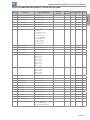
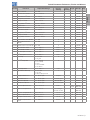
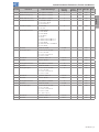
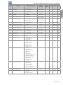
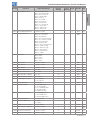
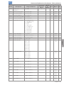
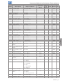
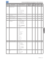
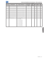
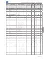
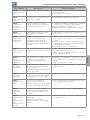
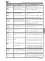
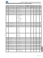
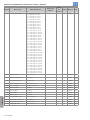
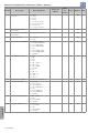
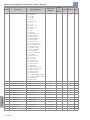
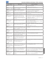
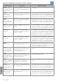
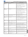
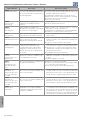
QUICK PARAMETER REFERENCE, FAULTS AND ALARMS
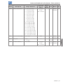
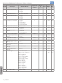
Param. Function Adjustable Range
Factory
Setting
User
Setting
Propr. Groups Pag.
P0000 Access to Parameters 0 to 9999 0 5-2
P0001 Speed Reference 0 to 65535 rpm ro READ 15-1
P0002 Motor Speed 0 to 65535 rpm ro READ 15-1
P0003 Motor Current 0.0 to 200.0 A ro READ 15-1
P0004 DC Link Voltage (Ud) 0 to 2000 V ro READ 15-1
P0005 Motor Frequency 0.0 to 500.0 Hz ro READ 15-2
P0006 VFD Status 0 = Ready
1 = Run
2 = Undervoltage
3 = Fault
4 = Self-Tuning
5 = Configuration
6 = DC-Braking
7 = Reserved
8 = Reserved
9 = Reserved
ro READ 15-2
P0007 Output Voltage 0 to 2000 V ro READ 15-3
P0009 Motor Torque -1000.0 to 1000.0 % ro READ 15-3
P0010 Output Power 0.0 to 6553.5 kW ro READ 15-3
P0011 Power Factor -1.00 to 1.00 ro READ 15-3
P0012 DI8 to DI1 Status Bit 0 = DI1
Bit 1 = DI2
Bit 2 = DI3
Bit 3 = DI4
Bit 4 = DI5
Bit 5 = DI6
Bit 6 = DI7
Bit 7 = DI8
ro READ, I/O 12-16
P0013 DO5 to DO1 Status Bit 0 = DO1
Bit 1 = DO2
Bit 2 = DO3
Bit 3 = DO4
Bit 4 = DO5
ro READ, I/O 12-22
P0014 AO1 Value 0.0 to 100.0 % ro READ, I/O 12-7
P0015 AO2 Value 0.0 to 100.0 % ro READ, I/O 12-7
P0016 FO % Value 0.0 to 100.0 % ro READ, I/O 12-13
P0017 FO Hz Value 0 to 20000 Hz ro READ, I/O 12-13
P0018 AI1 Value -100.0 to 100.0 % ro READ, I/O 12-1
P0019 AI2 Value -100.0 to 100.0 % ro READ, I/O 12-1
P0020 AI3 Value -100.0 to 100.0 % ro READ, I/O 12-1
P0021 FI % Value -100.0 to 100.0 % ro READ, I/O 12-11
P0022 FI Hz Value 0 to 20000 Hz ro READ, I/O 12-11
P0023 Main SW Version 0.00 to 655.35 ro READ 6-1
P0024 Sec. SW Version 0.00 to 655.35 ro READ 6-1
P0027 Plug-in Mod. Config. 0 = No Plug-in
1 to 8 = Reserved
9 = CFW500-CRS485
ro READ 6-1

4 | CFW501
Quick Parameter Reference, Faults and Alarms
English
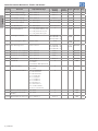
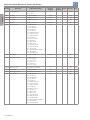
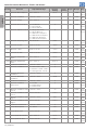
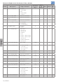
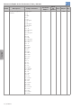
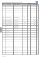
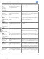
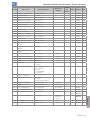
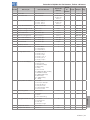
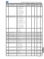
Param. Function Adjustable Range
Factory
Setting
User
Setting
Propr. Groups Pag.
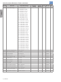
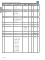
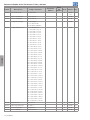
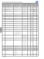
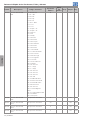
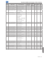
P0029 Power HW Config. 0 = Not Identified
1 = 200-240 V / 1.6 A
2 = 200-240 V / 2.6 A
3 = 200-240 V / 4.3 A
4 = 200-240 V / 7.0 A
5 = 200-240 V / 9.6 A
6 = 380-480 V / 1.0 A
7 = 380-480 V / 1.6 A
8 = 380-480 V / 2.6 A
9 = 380-480 V / 4.3 A
10 = 380-480 V / 6.1 A
11 = 200-240 V / 7.3 A
12 = 200-240 V / 10.0 A
13 = 200-240 V / 16.0 A
14 = 380-480 V / 2.6 A
15 = 380-480 V / 4.3 A
16 = 380-480 V / 6.5 A
17 = 380-480 V / 10.0 A
18 = 200-240 V / 24.0 A
19 = 380-480 V / 14.0 A
20 = 380-480 V / 16.0 A
21 = 500-600 V / 1.7 A
22 = 500-600 V / 3.0 A
23 = 500-600 V / 4.3 A
24 = 500-600 V / 7.0 A
25 = 500-600 V / 10.0 A
26 = 500-600 V / 12.0 A
27 = 200-240 V / 28.0 A
28 = 200-240 V / 33.0 A
29 = 380-480 V / 24.0 A
30 = 380-480 V / 31.0 A
31 = 500-600 V / 17.0 A
32 = 500-600 V / 22.0 A
33 = 200-240 V / 47.0 A
34 = 200-240 V / 56.0 A
35 = 380-480 V / 39.0 A
36 = 380-480 V / 49.0 A
37 = 500-600 V / 27.0 A
38 = 500-600 V / 32.0 A
ro READ 6-2
P0030 Heatsink Temperature -20 to 150 ºC ro READ 15-5
P0037 Motor Overload Ixt 0 to 100 % ro READ 14-3
P0042 Powered Time 0 to 65535 h ro READ 15-5
P0043 Enabled Time 0.0 to 6553.5 h ro READ 15-5
P0044 kWh Output Energy 0 to 65535 kWh ro READ 15-6
P0047 CONF State 0 to 999 ro READ 15-6
P0048 Present Alarm 0 to 999 ro READ 14-8
P0049 Present Fault 0 to 999 ro READ 14-8
P0050 Last Fault 0 to 999 ro READ 14-8
P0051 Current At Last Fault 0.0 to 200.0 A ro READ 14-9
P0052 DC Link At Last Fault 0 to 2000 V ro READ 14-9
P0053 Frequency At Last Fault 0.0 to 500.0 Hz ro READ 14-9
P0054 Temp. At Last Fault -20 to 150 ºC ro READ 14-10
P0055 Log. State Last Fault 0000h to FFFFh ro READ 14-10

CFW501 | 5
Quick Parameter Reference, Faults and Alarms
English
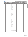
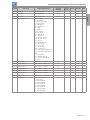
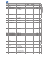
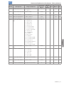
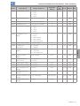
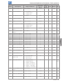
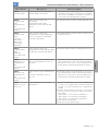
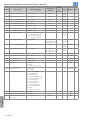
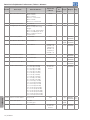
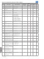
Param. Function Adjustable Range
Factory
Setting
User
Setting
Propr. Groups Pag.
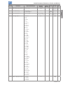
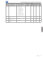
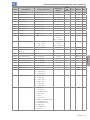
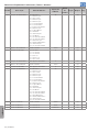
P0060 Second Fault 0 to 999 ro READ 14-8
P0061 Current at 2
nd
Fault 0.0 to 200.0 A ro READ 14-9
P0062 DC Link at 2
nd
Fault 0 to 2000 V ro READ 14-9
P0063 Frequency 2
nd
Fault 0.0 to 500.0 Hz ro READ 14-9
P0064 Temp. 2
nd
Fault -20 to 150 ºC ro READ 14-10
P0065 Log. State 2
nd
Fault 0000h to FFFFh ro READ 14-10
P0070 Third Fault 0 to 999 ro READ 14-8
P0071 Current at 3
rd
Fault 0.0 to 200.0 A ro READ 14-9
P0072 DC Link 3
rd
Fault 0 to 2000 V ro READ 14-9
P0073 Frequency 3
rd
Fault 0.0 to 500.0 Hz ro READ 14-9
P0074 Temp. 3
rd
Fault -20 to 150 ºC ro READ 14-10
P0075 Log. State 3
rd
Fault 0000h to FFFFh ro READ 14-10
P0080 Last Fault in “Fire Mode” 0 to 999 0 ro READ 14-10
P0081 Second Fault in “Fire
Mode”
0 to 999 0 ro READ 14-10
P0082 Third Fault in “Fire Mode” 0 to 999 0 ro READ 14-10
P0100 Acceleration Time 0.1 to 999.0 s 10.0 s BASIC 11-1
P0101 Deceleration Time 0.1 to 999.0 s 10.0 s BASIC 11-1
P0102 2
nd
Ramp Accel. Time 0.1 to 999.0 s 10.0 s 11-2
P0103 2
nd
Ramp Decel. Time 0.1 to 999.0 s 10.0 s 11-2
P0104 S Ramp 0 = Inactive
1 = Active
0 cfg 11-2
P0105 1
st
/2
nd
Ramp Sel. 0 = 1
st
Ramp
1 = 2
nd
Ramp
2 = DIx
3 = Serial/USB
4 = SoftPLC
2 I/O 11-3
P0106 3
rd
Ramp Time 0.1 to 999.0 s 5.0 s 11-3
P0120 Speed Ref. Backup 0 = Inactive
1 = Active
2 = Backup by P0121
1 7-8
P0121 Keypad Reference 0 to 18000 rpm 90 rpm 7-9
P0122 JOG Reference 0 to 18000 rpm 150 (125) rpm 7-9
P0133 Minimum Speed 0 to 18000 rpm 90 (75) rpm BASIC 7-8
P0134 Maximum Speed 0 to 18000 rpm 1800 (1500) rpm BASIC 7-8
P0135 Max. Output Current 0.0 to 200.0 A 1.5xI
nom
V/f,
VVW
BASIC,
MOTOR
11-8
P0136 Manual Torque Boost 0.0 to 30.0 % According to
inverter model
V/f BASIC,
MOTOR
9-4
P0137 Autom. Torque Boost 0.0 to 30.0 % 0.0 % V/f MOTOR 9-6
P0138 Slip Compensation -10.0 to 10.0 % 0.0 % V/f MOTOR 9-7
P0139 Output Current Filter 0 to 9999 ms 50 ms 8-1
P0140 Sleep Compensation
Filter
0 to 9999 ms 500 ms VVW 8-2

6 | CFW501
Quick Parameter Reference, Faults and Alarms
English
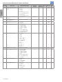
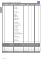
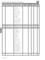
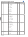
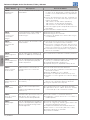
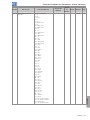
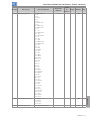
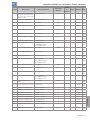
Param. Function Adjustable Range
Factory
Setting
User
Setting
Propr. Groups Pag.
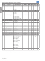
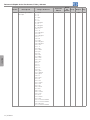
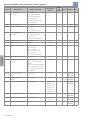
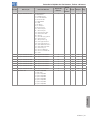
P0142 Max. Output Voltage 0.0 to 100.0 % 100.0 % cfg, V/f 9-5
P0143 Interm.Output Voltage 0.0 to 100.0 % 66.7 % cfg, V/f 9-5
P0144 Low Output Voltage 0.0 to 100.0 % 33.3 % cfg, V/f 9-5
P0145 Field Weakening Speed 0 to 18000 rpm 1800 (1500) rpm cfg, V/f 9-5
P0146 Intermediate Speed 0 to 18000 rpm 1200 (1000) rpm cfg, V/f 9-5
P0147 Low Speed point 0 to 18000 rpm 600 (500) rpm cfg, V/f 9-5
P0150 Ud Regul. Type V/f and
Current Limitation
0 = hold_Ud and desac_LC
1 = acel_Ud and desac_LC
2 = hold_Ud and hold_LC
3 = acel_Ud and hold_LC
0 cfg, V/f,
VVW
MOTOR 11-4
P0151 DC Regul. Level V/f 339 to 1200 V 400 V (P0296 = 0)
800 V (P0296 = 1)
1000 V (P0296 = 2)
V/f,
VVW
MOTOR 11-5
P0152 DC Link Regul. P Gain 0.00 to 9.99 1.50 V/f,
VVW
MOTOR 11-5
P0153 Dyn. Braking Level 339 to 1200 V 375 V (P0296 = 0)
750 V (P0296 = 1)
950 V (P0296 = 2)
V/f,
VVW
MOTOR 13-1
P0156 Overl.Curr. 100 % Speed 0.0 to 200.0 A 1.1xI
nom
MOTOR 14-2
P0157 Overl.Curr. 50 % Speed 0.0 to 200.0 A 1.0xI
nom
MOTOR 14-2
P0158 Overl.Curr. 20 % Speed 0.0 to 200.0 A 0.8xI
nom
MOTOR 14-2
P0178 Rated Flux 0.0 to 150.0 % 100.0 % MOTOR 10-4
P0200 Password 0 = Inactive
1 = Active
1 to 19999 = New password
0 HMI 5-3
P0202 Type of Control 0 to 2 = V/f
3 = VV W
0 cfg STARTUP 8-1
P0204 Load/Save Parameters 0 to 2 = Not Used
3 = Reset P0043
4 = Reset P0044
5 = Load 60 Hz
6 = Load 50 Hz
7 = Load User 1
8 = Load User 2
9 = Save User 1
10 = Save User 2
11 = Load SoftPLC
12 to 15 = Reserved
0 cfg 5-11
P0205 Main Parameter Display 0 to 1079 2 HMI 5-3
P0206 Secondary Parameter
Display
0 to 1079 1 HMI 5-3
P0208 Main Display Scale Factor 0.1 to 1000.0 % 100.0 % HMI 5-4

CFW501 | 7
Quick Parameter Reference, Faults and Alarms
English
Param. Function Adjustable Range
Factory
Setting
User
Setting
Propr. Groups Pag.
P0209 Main Display Eng. Unit 0 = None
1 = V
2 = A
3 = rpm
4 = s
5 = ms
6 = None
7 = m
8 = None
9 = None
10 = %
11 = ºC
12 = None
13 = Hz
14 = None
15 = h
16 = W
17 = kW
18 = None
19 = None
20 = min
21 = °F
22 = bar
23 = mbar
24 = psi
25 = Pa
26 = kPa
27 = MPa
28 = mwc
29 = mca
30 = gal
31 = l
32 = in
33 = ft
34 = m
3
35 = ft
3
36 = gal/s
37 = gal/min
38 = gal/h
39 = l/s
40 = l/min
41 = l/h
42 = m/s
43 = m/min
44 = m/h
45 = ft/s
46 = ft/min
47 = ft/h
48 = m
3
/s
49 = m
3
/min
50 = m
3
/h
51 = ft
3
/s
52 = ft
3
/min
53 = ft
3
/h
54 = According to P0510
55 = According to P0512
56 = None
57 = According to P0516
3 HMI 5-5

8 | CFW501
Quick Parameter Reference, Faults and Alarms
English
Param. Function Adjustable Range
Factory
Setting
User
Setting
Propr. Groups Pag.
P0210 Main Display Decimal
Point
0 = wxyz
1 = wxy.z
2 = wx.yz
3 = w.xyz
4 = According to P0511
5 = According to P0511
6 = Reserved
7 = According to P0511
0 HMI 5-4
P0211 Secondary Display Scale
Factor
0.1 to 1000.0 % 100.0 % HMI 5-4
P0212 Secondary Display
Decimal Point
See options in P0210 0 HMI 5-4
P0216 HMI Display Ilumination 0 = Inactive
1 = Active
1 HMI 5-6
P0220 LOC/REM Selection Src 0 = Always LOC
1 = Always REM
2 = HMI Key (LOC)
3 = HMI Key (REM)
4 = DIx
5 = Serial/USB (LOC)
6 = Serial/USB (REM)
7 = SoftPLC LOC
2 cfg I/O 7-5
P0221 LOC Reference Sel. 0 = Keypad
1 = AI1
2 = AI2
3 = AI3
4 = AI1 + AI2 > 0
5 = AI1 + AI2
6 = Serial/USB
7 = SoftPLC
8 = FI
9 = AI1 > 0
10 = AI2 > 0
11 = AI3 > 0
12 = FI > 0
0 cfg I/O 7-5
P0222 REM Reference Sel. See options in P0221 1 cfg I/O 7-5
P0223 LOC FWD/REV Selection 0 = Always FWD
1 = Always REV
2 = HMI Key (FWD)
3 = HMI Key (REV)
4 = DIx
5 = Serial/USB (FWD)
6 = Serial/USB (REV)
7 = SoftPLC
2 cfg I/O 7- 6
P0224 LOC Run/Stop Sel. 0 = HMI Keys
1 = DIx
2 = Serial/USB
3 = SoftPLC
0 cfg I/O 7- 6
P0225 LOC JOG Selection 0 = Disable
1 = HMI Key
2 = DIx
3 = Serial/USB
4 = SoftPLC
1 cfg I/O 7-7

CFW501 | 9
Quick Parameter Reference, Faults and Alarms
English
Param. Function Adjustable Range
Factory
Setting
User
Setting
Propr. Groups Pag.
P0226 REM FWD/REV Selection See options in P0223 0 cfg I/O 7-6
P0227 REM Run/Stop Sel. See options in P0224 1 cfg I/O 7-6
P0228 REM JOG Selection See options in P0225 2 cfg I/O 7-7
P0229 Stop Mode Selection 0 = Ramp to Stop
1 = Coast to Stop
2 = Quick Stop
0 cfg I/O 7-13
P0230 Dead Zone (AIs) 0 = Inactive
1 = Active
0 cfg I/O 12-2
P0231 AI1 Signal Function 0 = Speed Ref.
1 = Not Used
2 = Not Used
3 = SoftPLC
4 = PTC
5 = Main PID Feedback 1
6 = Main PID Feedback 2
7 = Not Used
8 = External PID 1 Feedback
9 = Not Used
5 cfg I/O 12-3
P0232 AI1 Gain 0.000 to 9.999 1.000 I/O 12-4
P0233 AI1 Signal Type 0 = 0 to 10 V / 20 mA
1 = 4 to 20 mA
2 = 10 V / 20 mA to 0
3 = 20 to 4 mA
0 cfg I/O 12-5
P0234 AI1 Offset -100.0 to 100.0 % 0.0 % I/O 12-4
P0235 AI1 Filter 0.00 to 16.00 s 0.15 s I/O 12-5
P0236 AI2 Signal Function See options in P0231 8 cfg I/O 12-3
P0237 AI2 Gain 0.000 to 9.999 1.000 I/O 12-4
P0238 AI2 Signal Type 0 = 0 to 10 V / 20 mA
1 = 4 to 20 mA
2 = 10 V / 20 mA to 0
3 = 20 to 4 mA
0 cfg I/O 12-5
P0239 AI2 Offset -100.0 to 100.0 % 0.0 % I/O 12-4
P0240 AI2 Filter 0.00 to 16.00 s 0.15 s I/O 12-5
P0241 AI3 Signal Function See options in P0231 0 cfg I/O 12-3
P0242 AI3 Gain 0.000 to 9.999 1.000 I/O 12-4
P0243 AI3 Signal Type 0 = 0 to 10 V / 20 mA
1 = 4 to 20 mA
2 = 10 V / 20 mA to 0
3 = 20 to 4 mA
4 = -10 to +10 V
0 cfg I/O 12-6
P0244 AI3 Offset -100.0 to 100.0 % 0.0 % I/O 12-4
P0245 AI3 Filter 0.00 to 16.00 s 0.15 s I/O 12-5

10 | CFW501
Quick Parameter Reference, Faults and Alarms
English
Param. Function Adjustable Range
Factory
Setting
User
Setting
Propr. Groups Pag.
P0246 Freq. Input FI 0 = Inactive
1 = Active
0 I/O 12-11
P0247 FI Gain 0.000 to 9.999 1.000 I/O 12-12
P0248 Min. FI 10 to 20000 Hz 10 Hz I/O 12-12
P0249 FI Offset -100.0 to 100.0 % 0.0 % I/O 12-12
P0250 Max. FI 10 to 20000 Hz 10000 Hz I/O 12-12
P0251 AO1 Function 0 = Speed Ref.
1 = Not Used
2 = Real Speed
3 = Not Used
4 = Not Used
5 = Output Current
6 = Active Current
7 = Output Power
8 = Not Used
9 = Motor Torque
10 = SoftPLC
11 = Not Used
12 = Motor Ixt
13 = P0696 Value
14 = P0697 Value
15 = Not Used
16 = External PID Output
17 = Not Used
18 = P0698 Value
16 I/O 12-8
P0252 AO1 Gain 0.000 to 9.999 1.000 I/O 12-9
P0253 AO1 Signal Type 0 = 0 to 10 V
1 = 0 to 20 mA
2 = 4 to 20 mA
3 = 10 V to 0
4 = 20 mA to 0
5 = 20 to 4 mA
0 I/O 12-9
P0254 AO2 Function See options in P0251 5 I/O 12-8
P0255 AO2 Gain 0.000 to 9.999 1.000 I/O 12-9
P0256 AO2 Signal Type See options in P0253 0 I/O 12-9
P0257 FO Function 0 = Speed Ref.
1 = Not Used
2 = Real Speed
3 = Not Used
4 = Not Used
5 = Output Current
6 = Active Current
7 = Output Power
8 = Not Used
9 = Motor Torque
10 = SoftPLC
11 = Not Used
12 = Motor Ixt
13 = P0696 Value
14 = P0697 Value
15 = Disable F.O.
16 = External PID Output
17 = Not Used
18 = P0698 Value
15 I/O 12-14

CFW501 | 11
Quick Parameter Reference, Faults and Alarms
English
Param. Function Adjustable Range
Factory
Setting
User
Setting
Propr. Groups Pag.
P0258 FO Gain 0.000 to 9.999 1.000 I/O 12-15
P0259 Min. FO 10 to 20000 Hz 10 Hz I/O 12-15
P0260 Max. FO 10 to 20000 Hz 10000 Hz I/O 12-15
P0263 DI1 Function 0 = Not Used
1 = Run/Stop
2 = General Enable
3 = Quick Stop
4 = FWD/REV
5 = LOC/REM
6 = JOG
7 = SoftPLC
8 = 2
nd
Ramp
9 = Not Used
10 = Not Used
11 = Not Used
12 = No Ext. Alarm
13 = No Ext. Fault
14 = Reset
15 = Disab.FlyStart
16 = Not Used
17 = Progr. Off
18 = Load User 1
19 = Load User 2
20 = Auto/Manual Main PID
21 = Auto/Manual External
PID
22 = Not Used
23 = Bypass Mode
24 = Activate Fire Mode
25 = PTC
1 cfg I/O 12-17
P0264 DI2 Function See options in P0263 0 cfg I/O 12-17
P0265 DI3 Function See options in P0263 20 cfg I/O 12-17
P0266 DI4 Function See options in P0263 21 cfg I/O 12-17
P0267 DI5 Function See options in P0263 0 cfg I/O 12-17
P0268 DI6 Function See options in P0263 0 cfg I/O 12-17
P0269 DI7 Function See options in P0263 0 cfg I/O 12-17
P0270 DI8 Function See options in P0263 0 cfg I/O 12-17
P0271 DI1 Function 0 = (DI1..DI8)NPN
1 = DI1 PNP
2 = (DI1..DI2)PNP
3 = (DI1..DI3)PNP
4 = (DI1..DI4)PNP
5 = (DI1..DI5)PNP
6 = (DI1..DI6)PNP
7 = (DI1..DI7)PNP
8 = (DI1..DI8)PNP
0 cfg I/O 12-15

12 | CFW501
Quick Parameter Reference, Faults and Alarms
English
Param. Function Adjustable Range
Factory
Setting
User
Setting
Propr. Groups Pag.
P0275 DO1 Function 0 = Not Used
1 = N* > Nx
2 = N > Nx
3 = N < Nx
4 = N = N*
5 = Zero Speed
6 = Is > Ix
7 = Is < Ix
8 = Torque > Tx
9 = Torque < Tx
10 = Remote
11 = Run
12 = Ready
13 = No Fault
14 = No F070
15 = Not Used
16 = No F0021/22
17 = No F0051
18 = No F072
19 = 4-20 mA OK
20 = P0695 Value
21 = Forward
22 = Ride-Through
23 = Pre-Charge OK
24 = Fault
25 = Time Enable > Hx
26 = SoftPLC
27 = Not Used
28 = F > Fx(1)
29 = F > Fx(2)
30 = Not Used
31 = Not Used
32 = No Alarm
33 = No Fault/Alarm
34 = Dry Pump Alarm/Fault
35 = Broken Belt Alarm/Fault
36 = Filter Mainten. Alarm/
Fault
37 = Sleep Mode
38 = Not Used
39 = Drive Bypass Contactor
40 = Mains Bypass
Contactor
41 = Fire Mode
42 = Self-tunning
11 I/O 12-22
P0276 DO2 Function See options in P0275 0 I/O 12-22
P0277 DO3 Function See options in P0275 24 I/O 12-22
P0278 DO4 Function See options in P0275 0 I/O 12-22
P0279 DO5 Function See options in P0275 0 I/O 12-22
P0281 Fx Frequency 0.0 to 500.0 Hz 4.0 Hz I/O 12-24
P0282 Fx Hysteresis 0.0 to 15.0 Hz 2.0 Hz I/O 12-24
P0287 Nx/Ny Hysteresis 0 to 900 rpm 18 (15) rpm I/O 12-24
P0288 Nx Speed 0 to 18000 rpm 120 (100) rpm I/O 12-24
P0289 Ny Speed 0 to 18000 rpm 1800 (1500) rpm I/O 12-24

CFW501 | 13
Quick Parameter Reference, Faults and Alarms
English
Param. Function Adjustable Range
Factory
Setting
User
Setting
Propr. Groups Pag.
P0290 Ix Current 0.0 to 200.0 A 1.0xI
nom
I/O 12-24
P0291 Zero Speed 0 to 18000 rpm 18 (15) rpm I/O 12-25
P0292 N = N* Band 0 to 18000 rpm 18 (15) rpm I/O 12-25
P0293 Tx Torque 0 to 200 % 100 % I/O 12-25
P0294 Hx Time 0 to 6553.5 h 432.0 h I/O 12-25
P0295 Inverter Rated Current 0.0 to 200.0 A According to
inverter model
ro READ 6-3
P0296 Line Rated Voltage 0 = 200 - 240 V
1 = 380 - 480 V
2 = 500 - 600 V
According to
inverter model
ro READ 6-3
P0297 Switching Frequency 2500 to 15000 Hz 5000 Hz MOTOR 6-3
P0299 DC-Braking Start Time 0.0 to 15.0 s 0.0 s MOTOR 11-10
P0300 DC-Braking Stop Time 0.0 to 15.0 s 0.0 s MOTOR 11-11
P0301 DC-Braking Speed 0 to 18000 rpm 30 rpm MOTOR 11-12
P0302 DC-Braking Voltage 0.0 to 100.0 % 20.0 % MOTOR 11-12
P0303 Skip Speed 1 0 to 18000 rpm 600 rpm 11-13
P0304 Skip Speed 2 0 to 18000 rpm 900 rpm 11-13
P0306 Skip Band 0 to 18000 rpm 0 rpm 11-13
P0308 Serial Address 0 to 255 1 NET 16-1
P0310 Serial Baud Rate 0 = 9600 bits/s
1 = 19200 bits/s
2 = 38400 bits/s
1 NET 16-1
P0311 Serial Bytes Config. 0 = 8 bits, no, 1
1 = 8 bits, even,1
2 = 8 bits, odd, 1
3 = 8 bits, no, 2
4 = 8 bits, even,2
5 = 8 bits, odd, 2
1 NET 16-1
P0312 Serial Protocol(1)(2) 0 = HMI(1)
1 = Reserved
2 = Modbus RTU(1)
3 = BACnet(1)
4 = N2(1)
5 = Reserved
6 = HMI(1)/Modbus RTU(2)
7 = Modbus RTU(2)
8 = HMI(1)/BACnet(2)
9 = BACnet(2)
10 = HMI(1)/N2(2)
11 = N2(2)
2 cfg NET 16-1
P0313 Comm. Error Action 0 = Inactive
1 = Ramp Stop
2 = General Disab.
3 = Go to LOC
4 = LOC Keep Enab.
5 = Cause Fault
1 NET 16-2
P0314 Serial Watchdog 0.0 to 999.0 s 0.0 s NET 16-1
P0316 Serial Interf. Status 0 = Inactive
1 = Active
2 = Watchdog Error
ro NET 16-1

14 | CFW501
Quick Parameter Reference, Faults and Alarms
English
Param. Function Adjustable Range
Factory
Setting
User
Setting
Propr. Groups Pag.
P0320 FlyStart/Ride-Through 0 = Inactive
1 = Flying Start
2 = FS / RT
3 = Ride-Through
0 cfg 11-9
P0331 Voltage Ramp 0.2 to 60.0 s 2.0 s 11-9
P0340 Auto-Reset Time 0 to 255 s 0 s 14-11
P0343 Mask for Faults and
Alarms
0000 to FFFFh
Bit 0 = F0074
Bit 1 = F0048
Bit 2...3 = Reserved
Bit 4 = F0076
Bit 5....15 = Reserved
0003h cfg 14-4
P0349 Ixt Alarm Level 70 to 100 % 85 % cfg 14-3
P0397 Control Config 0000 to FFFFh
Bit 0 = Slip Compens. Regen.
Bit 1 = Dead Time Compens.
Bit 2 = Io Stabilization
Bit 3 = P0297 Reduction
Temperature
000Bh cfg 8-2
P0398 Motor Service Factor 1.00 to 1.50 1.0 cfg MOTOR,
STARTUP
10-4
P0399 Motor Rated Eff. 50.0 to 99.9 % 75.0 % cfg,
VVW
MOTOR,
STARTUP
10-5
P0400 Motor Rated Voltage 200 to 600 V 220(230) V
(P0296 = 0)
380(400) V
(P0296 = 1)
575(525) V
(P0296 = 2)
cfg MOTOR,
STARTUP
10-5
P0401 Motor Rated Current 0 to 200.0 A 1.0xI
nom
cfg MOTOR,
STARTUP
10-6
P0402 Motor Rated Speed 0 to 30000 rpm 1710 (1425) rpm cfg MOTOR,
STARTUP
10-6
P0403 Motor Rated Frequency 0 to 500 Hz 60 (50) Hz cfg MOTOR,
STARTUP
10-6
P0404 Motor Rated Power 0 = 0.16 hp 0.12 kW
1 = 0.25 hp 0.19 kW
2 = 0.33 hp 0.25 kW
3 = 0.5 hp 0.37 kW
4 = 0.75 hp 0.55 kW
5 = 1 hp 0.75 kW
6 = 1.5 hp 1.1 kW
7 = 2 hp 1.5 kW
8 = 3 hp 2.2 kW
9 = 4 hp 3 kW
10 = 5 hp 3.7 kW
11 = 5.5 hp 4 kW
12 = 6 hp 4.5 kW
13 = 7.5 hp 5.5 kW
14 = 10 hp 7.5 kW
15 = 12.5 hp 9 kW
16 = 15 hp 11 kW
17 = 20 hp 15 kW
18 = 25 hp 18.5 kW
19 = 30 hp 22 kW
According to
inverter model
cfg MOTOR,
STARTUP
10-6

CFW501 | 15
Quick Parameter Reference, Faults and Alarms
English
Param. Function Adjustable Range
Factory
Setting
User
Setting
Propr. Groups Pag.
P0407 Motor Rated Power Fac 0.50 to 0.99 0.80 cfg MOTOR,
STARTUP
10-7
18-2
P0408 Run Self-Tuning 0 = Inactive
1 = No Rotation
0 cfg,
VVW
STARTUP 10-7
P0409 Stator Resistance 0.01 to 99.99 According to
inverter model
cfg,
VVW
MOTOR,
STARTUP
10-7
P0510 Ref. Eng. Unit 1 0 = None
1 = V
2 = A
3 = rpm
4 = s
5 = ms
6 = None
7 = m
8 = None
9 = None
10 = %
11 = ºC
12 = None
13 = Hz
14 = None
15 = h
16 = W
17 = kW
18 = None
19 = None
20 = min
21 = °F
22 = bar
23 = mbar
24 = psi
25 = Pa
26 = kPa
27 = MPa
28 = mwc
29 = mca
30 = gal
31 = l
32 = in
33 = ft
34 = m
3
35 = ft
3
36 = gal/s
37 = gal/min
38 = gal/h
39 = l/s
40 = l/min
41 = l/h
42 = m/s
43 = m/min
44 = m/h
45 = ft/s
46 = ft/min
47 = ft/h
48 = m
3
/s
49 = m
3
/min
50 = m
3
/h
51 = ft
3
/s
52 = ft
3
/min
53 = ft
3
/h
22 HMI 5-6
P0511 Indirect Indication Form 1 0 = wxyz
1 = wxy.z
2 = wx.yz
3 = w.xyz
1 HMI 5-7

16 | CFW501
Quick Parameter Reference, Faults and Alarms
English
Param. Function Adjustable Range
Factory
Setting
User
Setting
Propr. Groups Pag.
P0512 Ref. Eng. Unit 2 See options in P0510 11 HMI 5-7
P0513 Indirect Indication Form 2 0 = wxyz
1 = wxy.z
2 = wx.yz
3 = w.xyz
1 HMI 5-9
P0516 Ref. Eng. Unit 4 See options in P0510 13 HMI 5-9
P0517 Indirect Indication Form 4 0 = wxyz
1 = wxy.z
2 = wx.yz
3 = w.xyz
1 HMI 5-10
P0580 Fire Mode Configuration 0 = Inactive
1 = Active
2 = Active / P0134
3 = Active / P0581
4 = Active / Gen. Disable
0 cfg HVAC 18-30
P0581 Setpoint PID fire Mode -32768 to 32767 0 HVAC
P0582 Auto-reset configuration 0 = Limited
1 = Unlimited
0 cfg HVAC 18-31
P0583 Bypass Mode
Configuration
0 = Inactive
1 = Active/DIx
2 = Active/DIx+Failure
0 cfg HVAC 18-34
P0584 Bypass Contactor time 0.00 to 300.00 s 0.30 s cfg HVAC 18-34
P0585 Short Cycle Protection
Config.
0 = Inactive
1 = Active
0 cfg HVAC 18-3
P0586 Minimum RUN Time 0 to 650.00 s 5.00 s cfg HVAC 18-4
P0587 Minimum STOP Time 0.00 to 650.00 s 5.00 s cfg HVAC 18-4
P0588 Energy Saving Max.
Torque
0 to 85 % 60 % cfg, V/f HVAC 18-2
P0589 Energy Saving Min. Mag. 40 to 80 % 40 % cfg, V/f HVAC 18-2
P0590 Energy Saving Min. Speed 360 to 18000 rpm 600 (525) rpm cfg, V/f HVAC 18-3
P0591 Energy Saving Hysteresis 0 to 30 % 10 % cfg, V/f HVAC 18-3
P0680 Logical Status Bit 0 = Not Used
Bit 1 = Run Command
Bit 2 = Fire mode
Bit 3 = Bypass
Bit 4 = Quick Stop
Bit 5 = 2
nd
Ramp
Bit 6 = Config. Mode
Bit 7 = Alarm
Bit 8 = Running
Bit 9 = Enabled
Bit 10 = Forward
Bit 11 = JOG
Bit 12 = Remote
Bit 13 = Subvoltage
Bit 14 = Reserved
Bit 15 = Fault
ro READ,
NET
16-2
P0681 Speed in 13 bits -32768 to 32767 ro NET 16-2

CFW501 | 17
Quick Parameter Reference, Faults and Alarms
English
Param. Function Adjustable Range
Factory
Setting
User
Setting
Propr. Groups Pag.
P0682 Serial/USB Control Bit 0 = Ramp Enable
Bit 1 = General Enable
Bit 2 = Run Forward
Bit 3 = JOG Enable
Bit 4 = Remote
Bit 5 = 2
nd
Ramp
Bit 6 = Quick Stop
Bit 7 = Fault Reset
Bit 8....12 = Not Used
Bit 13 = Intern PID
Bit 14 = Extern PID
Bit 15 = Reserved
ro NET 7-12
16-2
P0683 Serial/USB Speed Ref. -32768 to 32767 ro NET 16-2
P0690 Logical Status 2 Bit 0....3 = Not Used
Bit 4 = Force Low Fs
Bit 5 = Sleep State
Bit 6 = Deceleration Ramp
Bit 7 = Acceleration Ramp
Bit 8 = Freeze Ramp
Bit 9 = Setpoint Ok
Bit 10 = DC Link Regulation
Bit 11 = 50Hz Config
Bit 12 = Ride Through
Bit 13 = Flying Start
Bit 14 = DC-Braking
Bit 15 = PWM
ro READ,
NET
7-11
P0695 DOx Value Bit 0 = DO1
Bit 1 = DO2
Bit 2 = DO3
Bit 3 = DO4
Bit 4 = DO5
ro NET 16-2
P0696 AOx Value 1 -32768 to 32767 ro NET 16-2
P0697 AOx Value 2 -32768 to 32767 ro NET 16-2
P0698 AOx Value 3 -32768 to 32767 ro NET 16-2
P0760 BACnet Dev Inst Hi 0 to 419 0 NET 16-2
P0761 BACnet Dev Inst Lo 0 to 9999 0 NET 16-2
P0762 Max Number of Master 0 to 127 127 NET 16-2
P0763 MS/TP Max info Frame 1 to 65535 1 NET 16-2
P0764 I-AM Msg transmition 0 = Power Up
1 = Continuos
0 NET 16-2
P0765 Token RX Qtde 0 to 65535 ro NET 16-2
P1000 SoftPLC Status 0 = No Applicative
1 = Installing App.
2 = Incompatible App.
3 = Stopped App.
4 = App. Running
ro HVAC 17-1
P1001 SoftPLC Command 0 = Stop Application
1 = Run Application
2 = Delete Application
1 cfg HVAC 17-1
P1002 Scan Cycle Time 0 to 65535 ms ro HVAC 17-1
P1003 SoftPLC Application 0 = User
1 = HVAC
1 cfg HVAC 17-2
P1010 HVAC Function Version 0.00 to 100.00 ro HVAC 17-2
P1011 Main PID Aut. Setpoint -32768 to 32767 0 HVAC 17-2
18-9
P1012 SoftPLC Parameter 3 -32768 to 32767 0 HVAC 17-2
P1013 SoftPLC Parameter 4 -32768 to 32767 0 HVAC 17-2

18 | CFW501
Quick Parameter Reference, Faults and Alarms
English
Param. Function Adjustable Range
Factory
Setting
User
Setting
Propr. Groups Pag.
P1014 Main PID Man. Setpoint 0.0 to 100.0 % 0.0 % HVAC 17-2
18-9
P1015 Main PID Feedback -32768 to 32767 ro HVAC 17-2
18-9
P1016 Main PID Output 0.0 to 100.0 % ro HVAC 17-2
18-9
P1017 Main PID Action Control 0 = Disable PID
1 = Direct Mode
2 = Reverse Mode
0 cfg HVAC 17-2
18-10
P1018 Main PID Operation Mode 0 = Always Automatic
1 = Always Manual
2 = A/M DI w/o bumpless
3 = A/M Net w/o bumpless
4 = A/M DI w/ bumpless
5 = A/M Net w/ bumpless
0 HVAC 17-2
18-11
P1019 Main PID Sampling Time 0.10 to 60.00 s 0.10 s HVAC 17-2
18-12
P1020 Main PID P. Gain 0.000 to 32.767 1.000 HVAC 17-2
18-12
P1021 Main PID I. Gain 0.000 to 32.767 0.430 HVAC 17-2
18-12
P1022 Main PID D. Gain 0.000 to 32.767 0.000 HVAC 17-2
18-12
P1023 Main PID Output Min.
Value
0.0 to 100.0 % 0.0 % HVAC 17-2
18-13
P1024 Main PID Output Max.
Value
0.0 to 100.0 % 100.0 % HVAC 17-2
18-13
P1025 SoftPLC Parameter 16 -32768 to 32767 0 HVAC 17-2
P1026 Main PID Feedback Conf. 0 = Sum Feed. 1 and 2
1 = Difference Feed. 1 and 2
2 = Average Feed. 1 and 2
0 cfg HVAC 17-2
18-13
P1027 Main PID Minimum
Feedback
-32768 to 32767 0 HVAC 17-2
18-14
P1028 Main PID Maximum
Feedback
-32768 to 32767 1000 HVAC 17-2
18-14
P1029 SoftPLC Parameter 20 -32768 to 32767 0 HVAC 17-2
P1030 Main PID Feedback
Alarm Conf.
0 = Disable
1 = Enable Alarm
2 = Enable Fault
0 cfg HVAC 17-2
18-15
P1031 Main PID Feedback Alarm
Low V.
-32768 to 32767 50 HVAC 17-2
18-15
P1032 Main PID Feedback Alarm
Low T.
0.00 to 650.00 s 5.00 s HVAC 17-2
18-16
P1033 Main PID Feedback Alarm
High V.
-32768 to 32767 900 HVAC 17-2
18-16
P1034 Main PID Feedback Alarm
High T.
0.00 to 650.00 s 5.00 s HVAC 17-2
18-17
P1035 SoftPLC Parameter 26 -32768 to 32767 0 HVAC 17-2
P1036 Sleep Mode Speed 0 to 18000 350 HVAC 17-2
18-17
P1037 Sleep Mode Time 0.00 to 650.00 s 5.00 s HVAC 17-2
18-18
P1038 Wake up Mode Deviation 0.0 to 100.0 % 5.0 % HVAC 17-2
18-18
P1039 Wake up Mode Time 0.00 to 650.00 s 10.00 s HVAC 17-2
18-18

CFW501 | 19
Quick Parameter Reference, Faults and Alarms
English
Param. Function Adjustable Range
Factory
Setting
User
Setting
Propr. Groups Pag.
P1040 HVAC Func. Logical
Status
0 to 65535 ro HVAC 17-2
18-28
P1041 SoftPLC Parameter 32 -32768 to 32767 0 HVAC 17-2
P1042 Dry Pump Config. 0 = Disable
1 = Enable Alarm
2 = Enable Fault
0 cfg HVAC 17-2
18-4
P1043 Dry Pump Speed 0 to 18000 400 HVAC 17-2
18-5
P1044 Dry Pump Torque 0.0 to 350.0 % 20.0 % HVAC 17-2
18-5
P1045 Dry Pump Time 0.00 to 650.00 s 20.00 s HVAC 17-2
18-5
P1046 Broken Belt Conf. 0 = Disable
1 = Enable Alarm
2 = Enable Fault
0 cfg HVAC 17-2
18-6
P1047 Broken Belt Speed 0 to 18000 400 HVAC 17-2
18-6
P1048 Broken Belt Torque 0.0 to 350.0 % 20.0 % HVAC 17-2
18-7
P1049 Broken Belt Time 0.00 to 650.00 s 20.00 s HVAC 17-2
18-7
P1050 Filter Mainten. Alarm Conf. 0 = Disable
1 = Enable Alarm
2 = Enable Fault
0 cfg HVAC 17-2
18-7
P1051 Filter Mainten. Alarm Time 0 to 32000 h 5000 h HVAC 17-2
18-8
P1052 Filter Mainten. Alarm
Counter
0 to 32000 h HVAC 17-2
18-8
P1053 SoftPLC Parameter 44 -32768 to 32767 0 HVAC 17-2
P1054 SoftPLC Parameter 45 -32768 to 32767 0 HVAC 17-2
P1055 SoftPLC Parameter 46 -32768 to 32767 0 HVAC 17-2
P1056 SoftPLC Parameter 47 -32768 to 32767 0 HVAC 17-2
P1057 SoftPLC Parameter 48 -32768 to 32767 0 HVAC 17-2
P1058 SoftPLC Parameter 49 -32768 to 32767 0 HVAC 17-2
P1059 SoftPLC Parameter 50 -32768 to 32767 0 HVAC 17-2
P1060 External PID Auto Setpoint -32768 to 32767 0 HVAC 17-2
18-20
P1061 External PID Man.
Setpoint
0.0 to 100.0 % 0.0 % HVAC 17-2
18-20
P1062 External PID Feedback -32768 to 32767 ro HVAC 17-2
18-21
P1063 External PID Output 0.0 to 100.0 % ro HVAC 17-2
18-21
P1064 External PID Action
Control
0 = Disable PID
1 = Direct Mode
2 = Reverse Mode
0 cfg HVAC 17-2
18-21
P1065 External PID Operation
Mode
0 = Always Automatic
1 = Always Manual
2 = A/M DI w/o bumpless
3 = A/M Net w/o bumpless
4 = A/M DI w/ bumpless
5 = A/M Net w/ bumpless
0 HVAC 17-2
18-22
P1066 External PID Sampling
Time
0.10 to 60.00 s 0.10 s HVAC 17-2
18-23

20 | CFW501
Quick Parameter Reference, Faults and Alarms
English
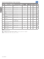
Param. Function Adjustable Range
Factory
Setting
User
Setting
Propr. Groups Pag.
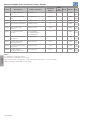
P1067 External PID P. Gain 0.000 to 32.767 1.000 HVAC 17-2
18-23
P1068 External PID I. Gain 0.000 to 32.767 0.430 HVAC 17-2
18-23
P1069 External PID D. Gain 0.000 to 32.767 0.000 HVAC 17-2
18-23
P1070 External PID Output Min.
Value
0.0 to 100.0 % 0.0 % HVAC 17-2
18-24
P1071 External PID Output Max.
Value
0.0 to 100.0 % 100.0 % HVAC 17-2
18-24
P1072 SoftPLC Parameter 63 -32768 to 32767 0 HVAC 17-2
P1073 External PID Minimum
Feedback
-32768 to 32767 0 HVAC 17-2
18-24
P1074 External PID Maximum
Feedback
-32768 to 32767 1000 HVAC 17-2
18-25
P1075 External PID Feedback
Alarm Conf.
0 = Disable
1 = Enable Alarm
2 = Enable Fault
0 HVAC 17-2
18-25
P1076 External PID Feedback
Alarm Low V.
-32768 to 32767 2 HVAC 17-2
18-26
P1077 External PID Feedback
Alarm Low T.
0.00 to 650.00 s 5.00 s HVAC 17-2
18-26
P1078 External PID Feedback
Alarm High V.
-32768 to 32767 900 HVAC 17-2
18-27
P1079 External PID Feedback
Alarm High T.
0.00 to 650.00 s 5.00 s HVAC 17-2
18-27
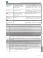
Notes:
ro = Read only parameter.
V/f = Available when V/f control mode is chosen.
cfg = Configuration parameter, value can be programmed only with motor stopped.
VVW = Available when VVW control mode is chosen.
Page is loading ...
Page is loading ...
Page is loading ...
Page is loading ...
Page is loading ...
Page is loading ...
Page is loading ...
Page is loading ...
Page is loading ...
Page is loading ...
Page is loading ...
Page is loading ...
Page is loading ...
Page is loading ...
Page is loading ...
Page is loading ...
Page is loading ...
Page is loading ...
Page is loading ...
Page is loading ...
Page is loading ...
Page is loading ...
Page is loading ...
Page is loading ...
Page is loading ...
Page is loading ...
Page is loading ...
Page is loading ...
Page is loading ...
Page is loading ...
Page is loading ...
Page is loading ...
Page is loading ...
Page is loading ...
Page is loading ...
Page is loading ...
Page is loading ...
Page is loading ...
Page is loading ...
Page is loading ...
Page is loading ...
Page is loading ...
Page is loading ...
Page is loading ...
Page is loading ...
Page is loading ...
Page is loading ...
Page is loading ...
Page is loading ...
Page is loading ...
Page is loading ...
Page is loading ...
Page is loading ...
Page is loading ...
Page is loading ...
Page is loading ...
Page is loading ...
Page is loading ...
Page is loading ...
Page is loading ...
Page is loading ...
-
 1
1
-
 2
2
-
 3
3
-
 4
4
-
 5
5
-
 6
6
-
 7
7
-
 8
8
-
 9
9
-
 10
10
-
 11
11
-
 12
12
-
 13
13
-
 14
14
-
 15
15
-
 16
16
-
 17
17
-
 18
18
-
 19
19
-
 20
20
-
 21
21
-
 22
22
-
 23
23
-
 24
24
-
 25
25
-
 26
26
-
 27
27
-
 28
28
-
 29
29
-
 30
30
-
 31
31
-
 32
32
-
 33
33
-
 34
34
-
 35
35
-
 36
36
-
 37
37
-
 38
38
-
 39
39
-
 40
40
-
 41
41
-
 42
42
-
 43
43
-
 44
44
-
 45
45
-
 46
46
-
 47
47
-
 48
48
-
 49
49
-
 50
50
-
 51
51
-
 52
52
-
 53
53
-
 54
54
-
 55
55
-
 56
56
-
 57
57
-
 58
58
-
 59
59
-
 60
60
-
 61
61
-
 62
62
-
 63
63
-
 64
64
-
 65
65
-
 66
66
-
 67
67
-
 68
68
-
 69
69
-
 70
70
-
 71
71
-
 72
72
-
 73
73
-
 74
74
-
 75
75
-
 76
76
-
 77
77
-
 78
78
-
 79
79
-
 80
80
-
 81
81
-
 82
82
-
 83
83


WEG CFW501 Quick start guide
- Type
- Quick start guide
- This manual is also suitable for
Ask a question and I''ll find the answer in the document
Finding information in a document is now easier with AI
in other languages
- español: WEG CFW501 Guía de inicio rápido
- português: WEG CFW501 Guia rápido
Related papers
Other documents
-
Lenovo P0510 Quick start guide
-
 AC Tech SCF SERIES Quick Reference Manual
-
Regin OPTIGO OP10-230 Operating instructions
-
 meitav-tec CTU2524-AC-SUPER-02-WET Product information
-
Bryton MAN-0001 User manual
-
Vacon 100 FLOW Installation guide
-
-
Ascon tecnologic D8 Quick start guide
-
AKO 1530 Operating instructions
-
Autonics MX4W Series LCD Multi Panel Meters User manual

