Autonics MX4W Series LCD Multi Panel Meters User manual

Type
User manual

Autonics MX4W Series LCD Multi Panel Meters are versatile and accurate measuring instruments designed to provide real-time monitoring and control of various electrical parameters. With their advanced features and user-friendly interface, these meters offer a wide range of applications in industrial, commercial, and residential settings.

Key capabilities of Autonics MX4W Series LCD Multi Panel Meters include:

  • Measurement of various electrical parameters: These meters can measure AC/DC voltage, AC/DC current, frequency, and power factor, making them suitable for a variety of electrical systems.
-|Transparent Guide|-
Thank you for choosing our Autonics product.
Read and understand the instruction manual and manual thoroughly before
using the product.
For your safety, read and follow the below safety considerations before using.
For your safety, read and follow the considerations written in the instruction
manual, other manuals and Autonics website.
Keep this instruction manual in a place where you can 󸠲nd easily.
The speci󸠲cations, dimensions, etc. are subject to change without notice for product
improvement. Some models may be discontinued without notice.
Follow Autonics website for the latest information.
Safety Considerations
Observe all ‘Safety Considerations’ for safe and proper operation to avoid hazards.
᜸ symbol indicates caution due to special circumstances in which hazards may
occur.
 Failure to follow instructions may result in serious injury or death.
01. Fail-safe device must be installed when using the unit with machinery that
may cause serious injury or substantial economic loss. (e.g. nuclear power
control, medical equipment, ships, vehicles, railways, aircraft, combustion
apparatus, safety equipment, crime / disaster prevention devices, etc.)
Failure to follow this instruction may result in personal injury, economic loss or 󸠲re.
02. 󸠳
high humidity, direct sunlight, radiant heat, vibration, impact or salinity
may be present.
Failure to follow this instruction may result in explosion or 󸠲re.
03. Install on a device panel to use.
Failure to follow this instruction may result in 󸠲re or electric shock.
04. Do not connect, repair, or inspect the unit while connected to a power source.
Failure to follow this instruction may result in 󸠲re or electric shock.
05. Check ‘Connections’ before wiring.
Failure to follow this instruction may result in 󸠲re.
06. Do not disassemble or modify the unit.
Failure to follow this instruction may result in 󸠲re or electric shock.
 Failure to follow instructions may result in injury or product damage.
01. 
22) cable or over and tighten the
terminal screw with a tightening torque of 0.78 to 0.98 N m.
Failure to follow this instruction may result in 󸠲re or malfunction due to contact
failure.
02. 󸠲
Failure to follow this instruction may result in 󸠲re or product damage.
03. Use a dry cloth to clean the unit, and do not use water or organic solvent.
Failure to follow this instruction may result in 󸠲re or electric shock.
04. 󸠳
into the unit.
Failure to follow this instruction may result in 󸠲re or product damage.
Cautions during Use
Follow instructions in ‘Cautions during Use’.
Otherwise, It may cause unexpected accidents.
Power supply should be insulated and limited voltage / current or Class 2, SELV power
supply device.
Install a power switch or circuit breaker in the easily accessible place for supplying or
disconnecting the power.
Keep away from high voltage lines or power lines to prevent inductive noise.
In case installing power line and input signal line closely, use line 󸠲lter or varistor at
power line and shielded wire at input signal line.
Do not use near the equipment which generates strong magnetic force or high
frequency noise.
󸠲 Connection with the varistor
Install the line filter
close to the panel meter
110 / 220 VACᜠ
Earth ground
HI
LOW
Panel meter HI
LOW
Panel meter
110 / 220 VACᜠ
This unit may be used in the following environments.
- Indoors (in the environment condition rated in ‘Speci󸠲cations’)
- Altitude max. 2,000 m
- Pollution degree 2
- Installation category II
LCD Multi Panel Meters

INSTRUCTION MANUAL
TCD210071AB
Product Components
Product
Bracket × 2
Instruction manual
Terminal cover × 1

Unit: mm, Use terminals of size speci󸠲ed
below.
Input and output are insulated from the
power.
≥3.0
≤6.0
ADC input
circuit and
display part
Option output
and
hold / zero Power
1 32 4 5 76 8 9
10
Dimensions
Unit: mm, For the detailed drawings, follow the Autonics website.
91.5
48
44.4
96 420
Bracket 󹌖
22
36 3
4.9 ≥ 116
≥ 52
92+0.8
0
45+0.6
0
Terminal cover
15.5
15.993.7
Ordering Information
This is only for reference, the actual product does not support all combinations.
For selecting the speci󸠲ed model, follow the Autonics webstie.
MX 4-- 
type
V: DC / AC voltage
A: DC / AC current

F: 24 - 240 VACᜠ / VDCᜡ

N: Indicator
1: NPN open collector
2: PNP open collector
Connections
Input
For using DC power, connect wires regardless of polarity.
Indicator model does not have the hold / zero terminal.
HOLD / ZERO
SOURCE
24 - 240 VACᜠ/ VDCᜡ
COM
1 2 3 4 5 6 7 8 9 10
V- A-
DC ± 500 mVDCᜡ / ± 200 mVDCᜡ /
± 50 mVDCᜡ
± 20 mA / 4 - 20 mA / ± 5 mA / ± 2 mA
AC 0 - 500 mVACᜠ / 0 - 200 mVACᜠ /
0 - 50 mVACᜠ 0 - 20 mA / 0 - 5 mA / 0 - 2 mA
DC
± 20 VDCᜡ / ± 5 VDCᜡ / 1 - 5 VDCᜡ /
± 2 VDCᜡ
± 500 mA / ± 200 mA / ± 50 mA
AC 0 - 20 VACᜠ / 0 - 5 VACᜠ / 0 - 2 VACᜠ 0 - 500 mA / 0 - 200 mA / 0 - 50 mA
DC
± 500 VDCᜡ / ± 200 VDCᜡ / ± 50 VDCᜡ
± 5 A / ± 2 A
AC 0 - 500 VACᜠ / 0 - 200 VACᜠ /
0 - 110 VACᜠ / 0 - 50 VACᜠ 0 - 5 A / 0 - 2 A
Output
1: NPN open collector
COMOUT2OUT1
1 2 3 4
HOLD/
ZERO
2: PNP open collector
COMOUT2OUT1
1 2 3 4
HOLD/
ZERO
󸠲
Model V- A-
Input type DC / AC voltage DC / AC current
 allowable input Dependent on the input type
+DC input ≈ -10 to 110 % F.S. for each measured input range
-DC input ≈ -110 to 110 % F.S. for each measured input range
AC input ≈ 10 to 110 % F.S. for each measured input range
Display method
12-segment LCD 01)
- measurement value display part: white, character height: 19 mm
- other display parts: red, green, yellow (indicator: white)
Display accuracy Dependent on the ambient temperature
23 ± 5 ℃ (DC input) ± 0.1 % F.S. rdg ± 2-digit ± 0.1 % F.S. rdg ± 2-digit 02)
23 ± 5 ℃ (AC input) ± 0.3 % F.S. rdg ± 3-digit ± 0.3 % F.S. rdg ± 3-digit
0 to 50 ± 0.5 % F.S. rdg ± 3-digit ± 0.5 % F.S. rdg ± 3-digit 03)
Display cycle 0.2 to 5.0 sec (select per 0.1 sec)
Display scale -9999 to 9999 (4-digit)
A / D conversion method
ΣΔ (Sigma Delta) analog-to-digital converter
Sampling cycle
(DC input) 50 ms
Sampling cycle
(AC input) 16.6 ms
Resolution 1 / 20,000
Preset output NPN / PNP open collector output model
Load voltage ≤ 30 VDCᜡ
Load current ≤ 100 mA
Residual voltage NPN open collector output: ≤ 1 VDCᜡ /
PNP open collector output: ≤ 2 VDCᜡ
Unit weight (packaged)
≈ 77 g (≈ 100 g)
Approval ᜢ ᜹ ᜧ
01) When using the unit at low temperature (below 0 ℃), display cycle is slow due to charateristics of LCD. Control
output operates normally.
02) 5 A terminal: ± 0.3 % F.S. rdg ± 3-digit
03) 5 A terminal: ± 1 % F.S. rdg ± 3-digit
Power supply 24 - 240 VDCᜡ ± 10 %, 24 - 240 VACᜠ ± 10 % 50 / 60 Hz
Power consumption DC: ≤ 3 W, AC: ≤ 5 VA
Insulation resistance ≥ 100 MΩ (500 VDCᜡ megger)
Dielectric strength
Between the charging part and the case: 3,000 VACᜠ 50 / 60 Hz for 1 min
Noise immunity ± 2 kV square wave noise (pulse width: 1 ㎲) by the noise simulator
Vibration 0.75 mm double amplitude at frequency of 10 to 55 Hz in each X, Y, Z
direction for 2 hours
Vibration
󹌓󹌔
0.5 mm double amplitude at frequency of 10 to 55 Hz in each X, Y, Z
direction for 10 min
Shock 300 m/s2 (≈ 30 G) in each X, Y, Z direction for 3 times
󹌓󹌔 100 m/s2 (≈ 10 G) in each X, Y, Z direction for 3 times
Ambient temperature -10 to 50 ℃, storage: -20 to 60 ℃ (no freezing or condensation)
Ambient humidity 35 to 85 %RH, storage: 35 to 85 %RH (no freezing or condensation)
Insulation type
Symbol: , double or reinforced insulation (dielectric strength
between the measurement input part and the power part: 1 kV)
Mode Setting
RUN
[MODE] 2 sec Parameter 1
group [MODE] 3 sec
RUN
[MODE] 4 sec Parameter 2
group [MODE] 3 sec
[MODE] Parameter 0
group [MODE] 3 sec
[◀] + [▲] 3 sec Zero adjustment Auto
[MODE] + [◀] + [▲]
5 sec Reset [MODE]
Parameter Setting
Some parameters are activated / deactivated depending on the model or setting of
other parameters. Refer to the description of each parameter.
If any key is not entered for 60 sec in each parameter, it returns to RUN mode.
After returning to RUN mode, press the [MODE] key within 2 sec, it returns to previous
parameter.
[MODE] key: Saves current setting value and moves to the next parameter.
[◀] key: Checks 󸠲xed value / Changes setting digits.
[▲] key: Changes setting values.
Parameter 1 group
Parameter Display Defaults Setting range
Display
condition
1-1 Input type
DCAC DC DC, -DC, AC -
1-2 Input range
01)
IN-R
50)0 [MX4W-V-F□]
Refer to Input Range and Display Range
1-1
Input
type
:
DC, AC
-50)0 1-1
Input
type
: -DC
%000 [MX4W-A-F□]
Refer to Input Range and Display Range
1-1
Input
type
:
DC, AC
-%000 1-1
Input
type
: -DC
1-3 Display
method
DISP STND
STND:
standard
, SCAL:
scale
,
FREQ: frequency
*, PF: power factor**
*1-1 Input
type: AC
**1-1 Input
type: ±DC
1-4
IN-T RMS AVG, RMS 1-1
Input
type
: AC
1-5
High-limit
display value
gradient
correction
SPAN !000 0.100 to 9.999 % 1-3
Display
method
:
STND
1-6
Low-limit
display value
deviation
correction
ZERO 00 -99 to 99
1-7 Decimal
point
position
DOT
00)0 [DC / AC voltage model]
0, 0.0, 0.00, 0.000
1-3
Display
method
:
SCAL
&
* 1-7
Decimal
point
position:
0.0, 0.00,
0.000
)000 [DC / AC current model]
0, 0.0, 0.00, 0.000
1-8
High-limit scale
H-SC -
Display value against max. measurement input*
1-9
Low-limit scale
L-SC -
Display value against min. measurement input*
1-10
High-limit
display value
gradient
correction
SPAN !000 0.100 to 9.999 %
1-11
Low-limit
display value
deviation
correction
02)
ZERO 00 -99 to 99
1-12 Decimal
point
position
03)
DOT
00)0 [DC / AC voltage model]
0, 0.0, 0.00, 0.000
1-3
Display
method
:
FREQ
)000 [DC / AC current model]
0, 0.0, 0.00, 0.000
1-13
High-limit
display value
gradient
correction
SPAN !000 0.100 to 9.999
1-14
Exponent of
SPAN eSPN 10-0
10-0: 10
0
, 10-1: 10
-1
, 10-2: 10
-2
, 10 1: 10
1
1-15 High-limit
input value
H-RG -Max. value of input range 1-3
Display
method
:
PF
1-16 Low-limit
input value
L-RG -Min. value of input range
1-17
Display unit dUNT
V[DC / AC voltage model]
V, MV, OFF -
A[DC / AC current model]
A, MA, HZ, OFF
01) When changing input range, the following parameters are reset.
- Parameter 1 group: display method, measurement method, decimal point position, high / low-limit scale, high-limit
display value gradient correction, exponent of span, high / low-limit input value, display unit
- Parameter 2 group: OUT1 / 2 output operation mode, OUT1 / 2 hysteresis
- Parameter 0 group: OUT1 / 2 high-limit output setting value, OUT1 / 2 low-limit output setting value, max. / min. peak
value
02)
Low-limit display value deviation correction range is within -99 to 99 for D
0
, D
-1
digit regardless of decimal point position.
03) Display range is variable according to decimal point position.
Dot Display range Frequency measurement range
0-9999 to 9999 1 to 1200 Hz
)0 -999.9 to 999.9 0.1 to 999.9 Hz
)00 -99.99 to 99.99 0.10 to 99.99 Hz
)000 -9.999 to 9.999 0.100 to 9.999 Hz
18, Bansong-ro 513Beon-gil, Haeundae-gu, Busan, Republic of Korea, 48002
󹌗󹌗󹌖󹌖󹌖󹌗
-|Transparent Guide|-
Parameter 2 group
Parameter Display Defaults Setting range
Display
condition
2-1 OUT1
operation
mode
OU!T OFF [Preset output model]
OFF, HIGH, LOW, HL, HL-G -
2-2 OUT2
operation
mode
OU@T OFF [Preset output model]
OFF, HIGH, LOW, HL, HL-G -
2-3 OUT1
hysteresis HYs1
0)1 [DC / AC voltage model]
Within 10 % of max. display range, digit
2-1 OUT1
operation
mode:
except
OFF
)001 [DC / AC current model]
Within 10 % of max. display range, digit
2-4 OUT2
hysteresis HYs2
0)1 [DC / AC voltage model]
Within 10 % of max. display range, digit
2-2 OUT2
operation
mode:
except
OFF
)001 [DC / AC current model]
Within 10 % of max. display range, digit
2-5
Startup
compensation
time
STaT 0)0 00.0 to 99.9 sec -
2-6 Peak
monitoring
delay time
PEaK 00 S 00 to 30 sec -
2-7 Display cycle DIsT )2 S 0.2 to 5.0 sec -
2-8 External
input
terminal
DI-T HOLD [Preset output model]
HOLD, ZERO -
2-9 Lock LOC OFF
OFF: unlock,
LOC1: lock parameter 1,
LOC2: lock parameter 1, 2,
LOC3: lock parameter 0, 1 and 2
-
Parameter 0 group
Parameter Display Defaults Setting range󹌔
Display
condition
0-1 OUT1 high-
limit output
setting value
OU!H
50)0 [DC / AC voltage & preset output model] 2-1 OUT1
operation
mode:
HIGH, HL,
HL-G
%000 [DC / AC current & preset output model]
0-2 OUT1 low-
limit output
setting value
OU!L
00)0 [DC / AC voltage & preset output model]
1-1 Input
type:
DC, AC
&
2-1 OUT1
operation
mode:
LOW, HL,
HL-G
)000 [DC / AC current & preset output model]
-50)0 [DC / AC voltage & preset output model]
1-1 Input
type: -DC
&
2-1 OUT1
operation
mode:
LOW, HL,
HL-G
-%000 [DC / AC current & preset output model]
0-3 OUT2 high-
limit output
setting value
OU@H
50)0 [DC / AC voltage & preset output model] 2-2 OUT2
operation
mode:
HIGH, HL,
HL-G
%000 [DC / AC current & preset output model]
0-4 OUT2 low-
limit output
setting value
OU@L
00)0 [DC / AC voltage & preset output model]
1-1 Input
type:
DC, AC
&
2-2 OUT2
operation
mode:
LOW, HL,
HL-G
)000 [DC / AC current & preset output model]
-50)0 [DC / AC voltage & preset output model]
1-1 Input
type: -DC
&
2-2 OUT2
operation
mode:
LOW, HL,
HL-G
-%000 [DC / AC current & preset output model]
0-5 Display max.
peak value 02) hPEK )0 Max. peak value in run mode
2-1 OUT1
operation
mode:
except
OFF
or
2-2 OUT2
operation
mode:
except
OFF
&
2-6 Peak
monitor-
ing delay
time:
except
00
0-6 Display min.
peak value 02) lPEK )0 Min. peak value in run mode
01) Setting range of OUT1 / 2 high / low-limit output setting value
1-1 input type +DC = -10 to 110 % of display range
1-1 input type -DC = -110 to 110 % of display range
1-1 input type AC = 0 to 110 % of display range
02) Reset: Press [◀] + [▲] key for over 1 sec
Input range Display range Input
impedance
Diaplay method󸠲
Diaplay method: SCAL 01)
0.0 - 500.0 VACᜠ 0.0 to 500.0 50)0
Decimals Display range
0-9999 to 9999
)0 -999.9 to 999.9
)00 -99.99 to 99.99
)000 -9.999 to 9.999
4.062 MΩ
0 - 500 VACᜠ 0 to 500 500
0.0 - 200.0 VACᜠ 0.0 to 200.0 20)0
0 - 200 VACᜠ 0 to 200 200
0.0 - 110.0 VACᜠ 0.0 to 110.0 11)0
0 - 110 VACᜠ 0 to 110 110
0.00 - 50.00 VACᜠ 0.00 to 50.00 5)00
162 kΩ
0.0 - 50.0 VACᜠ 0.0 to 50.0 5)0
0.00 - 20.00 VACᜠ 0.00 to 20.00 2)00
0.0 - 20.0 VACᜠ 0.0 to 20.0 2)0
0.000 - 5.000 VACᜠ 0.000 to 5.000 %000
0.00 - 5.00 VACᜠ 0.00 to 5.00 %00
0.000 - 2.000 VACᜠ 0.000 to 2.000 @000
0.00 - 2.00 VACᜠ 0.00 to 2.00 @00
0.0 - 500.0 mVACᜠ 0.0 to 500.0 50)0
4 kΩ
0 - 500 mVACᜠ 0 to 500 500
0.0 - 200.0 mVACᜠ 0.0 to 200.0 20)0
0 - 200 mVACᜠ 0 to 200 200
0.00 - 50.00 mVACᜠ 0.00 to 50.00 5)00
0.0 - 50.0 mVACᜠ 0.0 to 50.0 5)0
01) Connect to the input terminals whose 30 % to 100 % of the input range includes the max. value of the input
range to measure.
When the max. input value is under the 30 % of the input terminal range, display accuracy is degraded.
Input Range and Display Range
When the max. input value is over the 100 %, it may result in input terminal damage.
DC / AC voltage model (input type: DC)
Input range Display range Input
impedance
Diaplay method󸠲
Diaplay method: SCAL 01)
0.0 - 500.0 VDCᜡ 0.0 to 500.0 50)0
Decimals Display range
0-9999 to 9999
)0 -999.9 to 999.9
)00 -99.99 to 99.99
)000 -9.999 to 9.999
4.062 MΩ
0 - 500 VDCᜡ 0 to 500 500
0.0 - 200.0 VDCᜡ 0.0 to 200.0 20)0
0 - 200 VDCᜡ 0 to 200 200
0.00 - 50.00 VDCᜡ 0.00 to 50.00 5)00
0.0 - 50.0 VDCᜡ 0.0 to 50.0 5)0
0.00 - 20.00 VDCᜡ 0.00 to 20.00 2)00
162 kΩ
0.0 - 20.0 VDCᜡ 0.0 to 20.0 2)0
0.000 - 5.000 VDCᜡ 0.000 to 5.000 %000
0.00 - 5.00 VDCᜡ 0.00 to 5.00 %00
1.000 - 5.000 VDCᜡ 1.000 to 5.000 1-5A
1.00 - 5.00 VDCᜡ 1.00 to 5.00 1-5B
0.000 - 2.000 VDCᜡ 0.000 to 2.000 @000
0.00 - 2.00 VDCᜡ 0.00 to 2.00 @00
0.0 - 500.0 mVDCᜡ 0.0 to 500.0 50)0
4 kΩ
0 - 500 mVDCᜡ 0 to 500 500
0.0 - 200.0 mVDCᜡ 0.0 to 200.0 20)0
0 - 200 mVDCᜡ 0 to 200 200
0.00 - 50.00 mVDCᜡ 0.00 to 50.00 5)00
0.0 - 50.0 mVDCᜡ 0.0 to 50.0 5)0
01) Connect to the input terminals whose 30 % to 100 % of the input range includes the max. value of the input
range to measure.
When the max. input value is under the 30 % of the input terminal range, display accuracy is degraded.
DC / AC voltage model (input type: AC)
Input range Display range Input
impedance
Diaplay method󸠲
Diaplay method: SCAL 01)
-500.0 - 500.0 VDCᜡ -500.0 to 500.0 -50)0
Decimals Display range
0-9999 to 9999
)0 -999.9 to 999.9
)00 -99.99 to 99.99
)000 -9.999 to 9.999
4.062 MΩ
-500 - 500 VDCᜡ -500 to 500 -500
-200.0 - 200.0 VDCᜡ -200.0 to 200.0 -20)0
-200 - 200 VDCᜡ -200 to 200 -200
-50.00 - 50.00 VDCᜡ -50.00 to 50.00 -5)00
162 kΩ
-50.0 - 50.0 VDCᜡ -50.0 to 50.0 -5)0
-20.00 - 20.00 VDCᜡ -20.00 to 20.00 -2)00
-20.0 - 20.0 VDCᜡ -20.0 to 20.0 -2)0
-5.000 - 5.000 VDCᜡ -5.000 to 5.000 -%000
-5.00 - 5.00 VDCᜡ -5.00 to 5.00 -%00
-2.000 - 2.000 VDCᜡ -2.000 to 2.000 -@000
-2.00 - 2.00 VDCᜡ -2.00 to 2.00 -@00
-500.0 - 500.0 mVDCᜡ
-500.0 to 500.0 -50)0
4 kΩ
-500 - 500 mVDCᜡ -500 to 500 -500
-200.0 - 200.0 mVDCᜡ
-200.0 to 200.0 -20)0
-200 - 200 mVDCᜡ -200 to 200 -200
-50.00 - 50.00 mVDCᜡ
-50.00 to 50.00 -5)00
-50.0 - 50.0 mVDCᜡ -50.0 to 50.0 -5)0
01) Connect to the input terminals whose 30 % to 100 % of the input range includes the max. value of the input
range to measure.
When the max. input value is under the 30 % of the input terminal range, display accuracy is degraded.
DC / AC voltage model (input type: -DC)
DC / AC current model (input type: AC)
DC / AC current model (input type: DC)
DC / AC current model (input type: -DC)
Input range Display range Input
impedance
Diaplay method󸠲
Diaplay method: SCAL 01)
0.000 - 5.000 A 0.000 to 5.000 %000
Decimals Display range
0-9999 to 9999
)0 -999.9 to 999.9
)00 -99.99 to 99.99
)000 -9.999 to 9.999
0.02 Ω
0.00 - 5.00 A 0.00 to 5.00 %00
0.000 - 2.000 A 0.000 to 2.000 @000
0.00 - 2.00 A 0.00 to 2.00 @00
0.0 - 500.0 mA 0.0 to 500.0 50)0
0.87 Ω
0 - 500 mA 0 to 500 500
0.0 - 200.0 mA 0.0 to 200.0 20)0
0 - 200 mA 0 to 200 200
0.00 - 50.00 mA 0.00 to 50.00 5)00
0.0 - 50.0 mA 0.0 to 50.0 5)0
0.00 - 20.00 mA 0.00 to 20.00 2)00
21.87 Ω
0.0 - 20.0 mA 0.0 to 20.0 2)0
4.00 - 20.00 mA 4.00 to 20.00 4A20
4.0 - 20.0 mA 4.0 to 20.0 4B20
0.000 - 5.000 mA 0.000 to 5.000 %000
0.00 - 5.00 mA 0.00 to 5.00 %00
0.000 - 2.000 mA 0.000 to 2.000 @000
0.00 - 2.00 mA 0.00 to 2.00 @00
01) Connect to the input terminals whose 30 % to 100 % of the input range includes the max. value of the input
range to measure.
When the max. input value is under the 30 % of the input terminal range, display accuracy is degraded.
Input range Display range Input
impedance
Diaplay method󸠲
Diaplay method: SCAL 01)
-5.000 - 5.000 A -5.000 to 5.000 -%000
Decimals Display range
0-9999 to 9999
)0 -999.9 to 999.9
)00 -99.99 to 99.99
)000 -9.999 to 9.999
0.02 Ω
-5.00 - 5.00 A -5.00 to 5.00 -%00
-2.000 - 2.000 A -2.000 to 2.000 -@000
-2.00 - 2.00 A -2.00 to 2.00 -@00
-500.0 - 500.0 mA -500.0 to 500.0 -50)0
0.87 Ω
-500 - 500 mA -500 to 500 -500
-200.0 - 200.0 mA -200.0 to 200.0 -20)0
-200 - 200 mA -200 to 200 -200
-50.00 - 50.00 mA -50.00 to 50.00 -5)00
-50.0 - 50.0 mA -50.0 to 50.0 -5)0
-20.00 - 20.00 mA -20.00 to 20.00 -2)00
21.87 Ω
-20.0 - 20.0 mA -20.0 to 20.0 -2)0
-5.000 - 5.000 mA -5.000 to 5.000 -%000
-5.00 - 5.00 mA -5.00 to 5.00 -%00
-2.000 - 2.000 mA -2.000 to 2.000 -@000
-2.00 - 2.00 mA -2.00 to 2.00 -@00
01) Connect to the input terminals whose 30 % to 100 % of the input range includes the max. value of the input
range to measure.
When the max. input value is under the 30 % of the input terminal range, display accuracy is degraded.
Input range Display range Input
impedance
Diaplay method󸠲
Diaplay method: SCAL 01)
0.000 - 5.000 A 0.000 to 5.000 %000
Decimals Display range
0-9999 to 9999
)0 -999.9 to 999.9
)00 -99.99 to 99.99
)000 -9.999 to 9.999
0.02 Ω
0.00 - 5.00 A 0.00 to 5.00 %00
0.000 - 2.000 A 0.000 to 2.000 @000
0.00 - 2.00 A 0.00 to 2.00 @00
0.0 - 500.0 mA 0.0 to 500.0 50)0
0.87 Ω
0 - 500 mA 0 to 500 500
0.0 - 200.0 mA 0.0 to 200.0 20)0
0 - 200 mA 0 to 200 200
0.00 - 50.00 mA 0.00 to 50.00 5)00
0.0 - 50.0 mA 0.0 to 50.0 5)0
0.00 - 20.00 mA 0.00 to 20.00 2)00
21.87 Ω
0.0 - 20.0 mA 0.0 to 20.0 2)0
0.000 - 5.000 mA 0.000 to 5.000 %000
0.00 - 5.00 mA 0.00 to 5.00 %00
0.000 - 2.000 mA 0.000 to 2.000 @000
0.00 - 2.00 mA 0.00 to 2.00 @00
01) Connect to the input terminals whose 30 % to 100 % of the input range includes the max. value of the input
range to measure.
When the max. input value is under the 30 % of the input terminal range, display accuracy is degraded.
Error
Error display is released automatically when it is in the measured and display range.
Display Description Troubleshooting
HHHH Flashes when measurement input is exceeded the
max. allowable input (110 %) Disconnect power supply
and check the cables.
LLLL Flashes when measurement input is exceeded the
min. allowable input (-DC: -110 % / DC, AC: -10 %)
D-HH Flashes when measurement input is exceed the
max. display value (9999) Reset within the display
range.
D-LL Flashes when measurement input is exceed the
min. display value (-9999)
F-HH Flashes when input frequency is exceeded the max.
display value of measured range
-PF-H Flashes when power factor display value to
measured input is over than LAG 0.50
PF-L Flashes when power factor display value to
measured input is less than LEAD -0.50
OVER Flashes twice when it exceeds zero range (±99)
and returns to run mode Reset within the zero range.
Reset
01. 󸠳
alternately for 0.5 sec in turn.
02. Change the setting value as YES by pressing the direction keys.
03. 
to run mode.
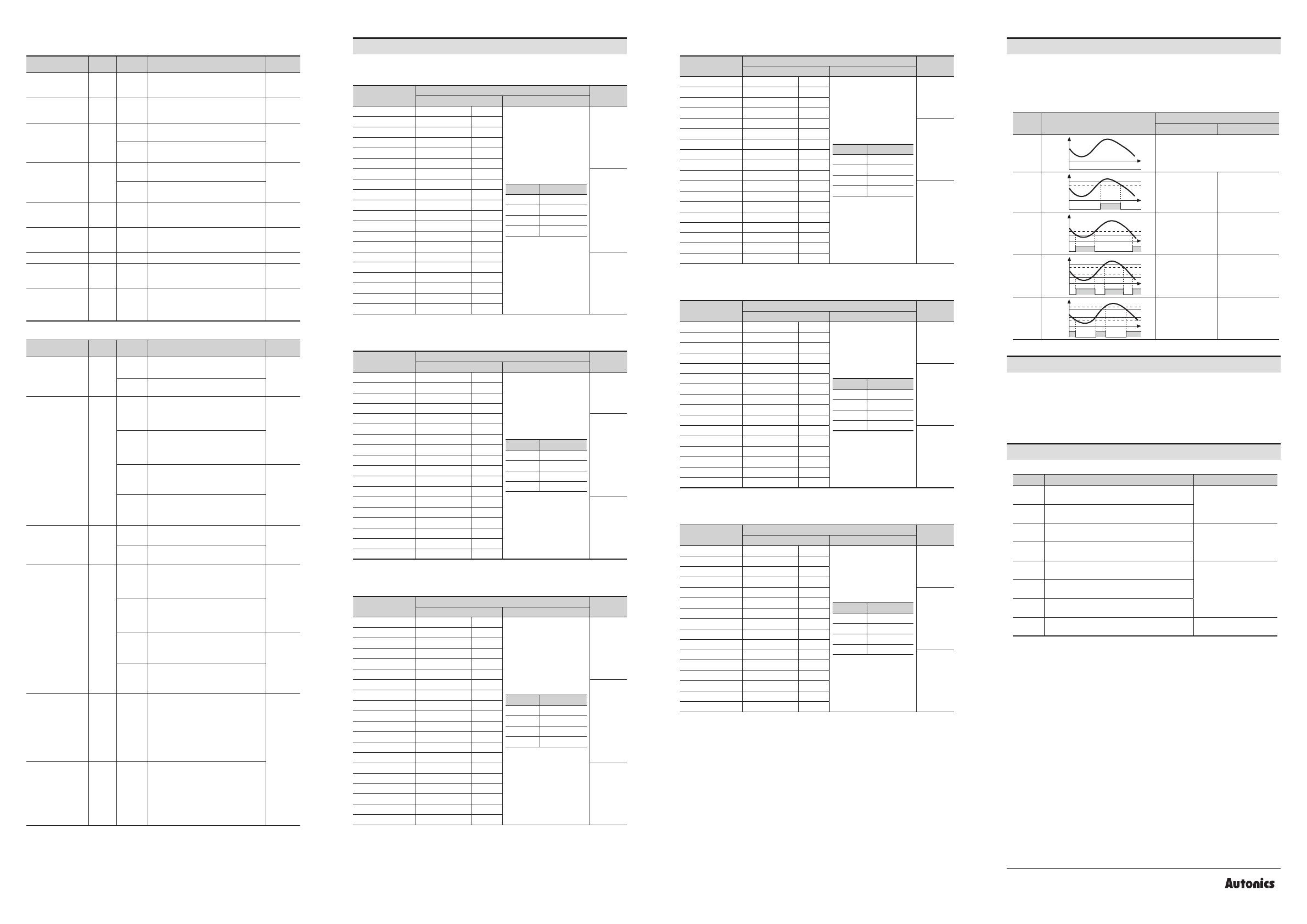
Output Operation Mode
The below describes based on OUT1.
OUT1 and OUT2 of output operations are same. It operates individually by the set output
operation mode.
When changing output operation mode, high-limit / low-limit output setting value, hysteresis
are reset.
MODE Output operation Preset output
ON OFF
OFF
OUT
No output
HIGH
Hys
OUT
OUT.H
OU1.H
≤ Display value
OU1.H - HYS.1
Display value
LOW Hys
OUT
OUT.L
OU1.L
≥ Display value
OU1.L + HYS.1
Display value
HL
Hys
OUT
OUT.H
OUT.L
OU1.L
≥ Display value
/
OU1.H
≤ Display value
OU1.L + HYS.1
≤ Display value
/
OU1.H - HYS.1
≥ Display value
HL-G Hys
OUT
OUT.H
OUT.L
OU1.L
≤ Display value
≤ OU1.H
+ HYS.1
OU1.L - HYS.1
≥ Display value
/
OU1.H + HYS.1
≤ Display value
  • Page 1 1
  • Page 2 2

Autonics MX4W Series LCD Multi Panel Meters User manual

Type
User manual

Autonics MX4W Series LCD Multi Panel Meters are versatile and accurate measuring instruments designed to provide real-time monitoring and control of various electrical parameters. With their advanced features and user-friendly interface, these meters offer a wide range of applications in industrial, commercial, and residential settings.

Key capabilities of Autonics MX4W Series LCD Multi Panel Meters include:

  • Measurement of various electrical parameters: These meters can measure AC/DC voltage, AC/DC current, frequency, and power factor, making them suitable for a variety of electrical systems.

Ask a question and I''ll find the answer in the document

Finding information in a document is now easier with AI