Page is loading ...

CA20, 871, 872, and 873 COMBINE ADAPTER
HEADER SELECTOR VALVE REPAIR KIT (MD #279833)
INSTALLATION INSTRUCTIONS
147476 Revision C Page 1 of 5
The Combine Adaptor Header Selector Valve Repair Kit (MD #279833) includes the necessary hardware
to allow the use of valve (MD #133418) with the following models of MacDon Combine Adapter: 871, 872,
873, and CA20.
A list of parts included in the kit is provided on page 2.
NOTE: Keep your MacDon publications up-to-date. The most current version of this instruction can be
downloaded from our Dealer-only site (https://portal.macdon.com) (login required).
NOTE: This instruction is available in English only.
Installation Time
It should take approximately 45 minutes to install this kit.
Conventions
The following conventions are followed in this document:
Right and left are determined from the operator’s position. The front of the header is the side that
faces the crop; the back of the header is the side that connects to the combine.
Unless otherwise noted, use the standard torque values provided in the header operator’s manual
and technical manual.
Table of Contents
Installation Time .......................................................................................................................................... 1
Conventions ................................................................................................................................................ 1
Table of Contents ........................................................................................................................................ 1
Parts List .................................................................................................................................................... 2
Removing Header Selector Valve .............................................................................................................. 3
Installing Header Selector Valve ............................................................................................................... 4

CA20, 871, 872, and 873 COMBINE ADAPTER
HEADER SELECTOR VALVE REPAIR KIT (MD #279833)
INSTALLATION INSTRUCTIONS
147476 Revision C Page 2 of 5
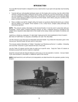
Part List
This kit includes the following parts:
Ref
Part
Number
Description
Quantity
1
133418
VALVE-SELECTOR
1
A
135250
BOLT – HEX HD. 0.025-20UNC X 2.75 IN LG ZN
2
B
135248
NUT – FLG SMTH FACE ¼-20 NC GR5 ZP CTR LK DT THD
2
C
21455
NUT – FLG (SERR FACE) ¼-20 NC GR5 ZP
2
Figure 1: Selector Valve Kit Parts
Table 1: Kit Parts (MD #279833)

CA20, 871, 872, and 873 COMBINE ADAPTER
HEADER SELECTOR VALVE REPAIR KIT (MD #279833)
INSTALLATION INSTRUCTIONS
147476 Revision C Page 3 of 5
Installation Instructions
To install the Combine Adaptor Header Selector Valve Repair Kit (MD #279833), follow these procedures
in order.
Removing Header Selector Valve Manifold
1. Read the instructions thoroughly and verify that you have all parts in the included parts list.
2. Lower header to the ground.
3. Raise reel arms until level. This will help reduce hydraulic oil pressure on reel fore-aft cylinders.
DANGER
To avoid bodily injury or death from unexpected startup of the machine, always stop the engine
and remove the key from the ignition before leaving the operator’s station for any reason.
WARNING
Remove pressure before disconnecting hydraulic
lines. If a header is attached to the windrower, set
header on the ground or lower the header onto the
safety props before starting this installation.
4. Stop engine and remove key.
NOTE: The CA20 selector valve manifold is located to
the left side of the conveyor (Figure 2).
5. CA20 only: Remove access cover bolts and cover.
Retain hardware for reuse.
NOTE: The 871/872/873 selector valve is located to
the right side of the conveyor and mounted on the
frame (Figure 3).
6. Disconnect the electrical plugs from coils.
CAUTION
Loosen hydraulic lines gradually. This will reduce the
chance of rapid high pressure oil discharge.
7. Remove hose connections at valve manifold end.
NOTE: To avoid contamination, protect hose ends with plastic, or use an appropriate hose plug.
8. Remove the two mounting bolts, washers, and nuts. Retain for reuse.
Figure 2: Selector Valve CA20
Figure 3: Selector valve 871/872/873

CA20, 871, 872, and 873 COMBINE ADAPTER
HEADER SELECTOR VALVE REPAIR KIT (MD #279833)
INSTALLATION INSTRUCTIONS
147476 Revision C Page 4 of 5
Installing Header Selector Valve
1. Remove parts from kit.
2. Adjust fittings on new valve to match fitting
orientation on old valve.
3. 871/872/873 only: Bolt valve (MD #133418) to
header mounted bracket using hardware retained
from step 9.
4. CA20 only: Bolt valve into hydraulic compartment
as shown using hardware supplied with
kit (Figure 4).
NOTE: Serrated nut (B) is installed on inside of
adaptor frame and smooth faced distorted head nut
(B) is installed on the outside of the adapter frame.
5. Connect hydraulic hoses from valve ports P1 and
P2 to the couplers for fore-aft control on your
combine.
NOTE: P1 (green cable tie), is the fore side of the
circuit, while P2 (red cable tie), is the aft side.
.
Figure 4: Mounting Selector Valve (CA20 only)
A – MD #135248 B – MD #21455
C – MD #135248
Figure 5: Ports Diagram
(fittings removed for clarity)

CA20, 871, 872, and 873 COMBINE ADAPTER
HEADER SELECTOR VALVE REPAIR KIT (MD #279833)
INSTALLATION INSTRUCTIONS
147476 Revision C Page 5 of 5
NOTE: Identify hydraulic hoses by connection points at barrel or rod end of cylinders and trace back.
Header model
Fore-aft “fore” (green) hose from
valve port “A1” connects to:
Fore-aft “aft” (red) hose from
valve port “B1” connects to:
972/973/974 (double reel)
Right fore-aft cylinder (green)
barrel end
Left fore-aft cylinder (red)
rod end
972/973 (single reel)
Right fore-aft cylinder (green)
rod end
Left fore-aft cylinder (red)
rod end
D60 (double reel)
FD70
Right fore-aft cylinder (green)
rod end
Center fore-aft cylinder (red)
barrel end
D50
D60 (single reel)
Left Fore-Aft cylinder (green)
barrel end
Right fore-aft cylinder (red)
barrel end
Header Model:
Cylinder Port
Valve Port
All
Barrel end tilt cylinder
A2
All
Rod end tilt cylinder
B2
6. Connect the hydraulic hoses to the tilt and fore-aft cylinders using tables 2 and 3 as a reference.
7. Reconnect the wiring harness to the solenoids on the new selector valve. Note that new valve has
only two solenoids. Securely tape the unused third harness connector back to the harness using
electrical tape. The third coil may or may not initially be present.
8. CA20 only: Reinstall cover of hydraulic compartment using hardware retained from step 5.
Table 2: Hose Connection A1, B1 Ports
Table 3: Hose Connection A2, B2 ports
/