Page is loading ...

Form 169076 Revision C
Model D50 and D60
Harvest Header
®
with
CA20 Combine Adapter
UNLOADING and
ASSEMBLY INSTRUCTIONS
for
NORTH AMERICAN SHIPMENTS
Published: October 2010

Form 169076 Revision C
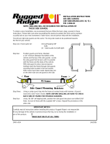
INTRODUCTION
This instructional manual describes the unloading, set up and pre-delivery requirements for the MacDon D50 and
D60 Harvest Headers
®
with a CA20 Combine Adapter.
Use the Table of Contents to guide you to specific areas.
Retain this manual for future reference.
CAREFULLY READ ALL THE MATERIAL PROVIDED BEFORE ATTEMPTING TO UNLOAD, ASSEMBLE, OR
USE THE MACHINE.
D60 HARVEST HEADER
®
D50 HARVEST HEADER
®

TABLE OF CONTENTS
Form 169076 Revision C
1
GENERAL SAFETY .................................................................................................................................................. 3
RECOMMENDED TORQUES ................................................................................................................................... 5
A. GENERAL ............................................................................................................................................. 5
B. SAE BOLTS .......................................................................................................................................... 5
C. METRIC BOLTS ................................................................................................................................... 5
D. HYDRAULIC FITTINGS ........................................................................................................................ 6
ENGLISH/METRIC EQUIVALENTS .......................................................................................................................... 7
STEP 1. UNLOAD HEADER .................................................................................................................................... 8
STEP 2. LOWER HEADER ..................................................................................................................................... 9
STEP 3. REMOVE SHIPPING STANDS ............................................................................................................... 10
STEP 4. INSTALL REEL LIFT CYLINDERS ......................................................................................................... 11
STEP 5. RE-POSITION GEARBOX ...................................................................................................................... 14
A. Filler Cap ............................................................................................................................................. 15
STEP 6. INSTALL REEL SPEED SENSOR .......................................................................................................... 16
A. REMOVE COVER ............................................................................................................................... 16
I. D60 HARVEST HEADER ...................................................................................................................... 16
II. D50 HARVEST HEADER ...................................................................................................................... 17
B. JOHN DEERE ..................................................................................................................................... 18
I. D60 HARVEST HEADER ...................................................................................................................... 18
II. D50 HARVEST HEADER ...................................................................................................................... 19
C. LEXION 500 SERIES .......................................................................................................................... 21
I. D60 HARVEST HEADER ...................................................................................................................... 21
II. D50 HARVEST HEADER ...................................................................................................................... 23
D. LEXION 400 SERIES .......................................................................................................................... 24
I. D60 HARVEST HEADER ...................................................................................................................... 24
II. D50 HARVEST HEADER ...................................................................................................................... 25
E. AGCO SERIES ................................................................................................................................... 26
I. D60 HARVEST HEADER ...................................................................................................................... 26
II. D50 HARVEST HEADER ...................................................................................................................... 27
F. INSTALL COVER ................................................................................................................................ 28
I. D60 HARVEST HEADER ...................................................................................................................... 28
II. D50 HARVEST HEADER ...................................................................................................................... 28
STEP 7. INSTALL OPTIONS................................................................................................................................. 28
STEP 8. SET UP ADAPTER .................................................................................................................................. 29
A. CENTER-LINK KIT ............................................................................................................................. 29
B. FLIGHTING EXTENSIONS ................................................................................................................. 29
C. STRIPPER BARS ............................................................................................................................... 30
D. CR FEEDER DEFLECTORS .............................................................................................................. 30
STEP 9. ATTACH TO COMBINE .......................................................................................................................... 31
A. CASE IH .............................................................................................................................................. 31
B. CASE IH 23, 25 SERIES .................................................................................................................... 34
C. JOHN DEERE 60 SERIES .................................................................................................................. 37
D. JOHN DEERE 50 SERIES .................................................................................................................. 39
E. CAT LEXION 400, 500 SERIES ......................................................................................................... 41
F. NEW HOLLAND .................................................................................................................................. 45
G. AGCO .................................................................................................................................................. 47
STEP 10.CONNECT REEL TO FORE-AFT CYLINDERS ..................................................................................... 50
STEP 11.ATTACH CAM ARMS ............................................................................................................................. 51
STEP 12.INSTALL REEL ENDSHIELDS ............................................................................................................... 52
STEP 13.REMOVE SHIPPING SUPPORTS .......................................................................................................... 53
STEP 14.INSTALL CROP DIVIDERS .................................................................................................................... 54
A. D60 ...................................................................................................................................................... 54
B. D50 ...................................................................................................................................................... 55

TABLE OF CONTENTS
Form 169076 Revision C
2
STEP 15.INSTALL HEADER ENDSHIELDS ......................................................................................................... 56
A. HINGED ENDSHIELD ........................................................................................................................ 56
B. NON-HINGED ENDSHIELD ............................................................................................................... 58
STEP 16.POSITION TRANSPORT LIGHTS .......................................................................................................... 59
STEP 17.PRE-DELIVERY INSPECTION ............................................................................................................... 60
A. TIRE PRESSURE (Transport and Stabilizer Wheel Options) ............................................................ 60
B. WHEEL BOLT TORQUE (Transport and Stabilizer Wheel Options) .................................................. 60
C. WOBBLE BOX .................................................................................................................................... 60
D. GEARBOX OIL.................................................................................................................................... 61
E. HYDRAULIC RESERVOIR ................................................................................................................. 61
F. SICKLE DRIVE BELT TENSION ........................................................................................................ 61
I. NON-TIMED DRIVE - SK and DK ......................................................................................................... 61
II. TIMED DRIVE - DK ............................................................................................................................... 62
G. REEL CENTERING ............................................................................................................................ 63
H. SIDE DRAPER TENSION ................................................................................................................... 64
I. HEADER MAIN FLOAT ...................................................................................................................... 65
J. SKID SHOE SETTINGS ..................................................................................................................... 67
K. REEL TINE TO CUTTERBAR CLEARANCE ..................................................................................... 68
L. DRAPER SEAL ................................................................................................................................... 69
M. LUBRICATE HEADER ........................................................................................................................ 70
N. MANUALS ........................................................................................................................................... 74
STEP 18.RUN-UP THE HEADER........................................................................................................................... 75
A. KNIFE SPEED .................................................................................................................................... 76
STEP 19.POST RUN-UP ADJUSTMENTS ............................................................................................................ 77
A. KNIFE .................................................................................................................................................. 77

Form 169076 Revision C
3
GENERAL SAFETY
CAUTION
The following are general farm safety
precautions that should be part of your
operating procedure for all types of machinery.
Protect yourself:
• When assembling, operating and servicing
machinery, wear all the protective clothing
and personal safety devices that COULD
be necessary for the job at hand. Don't
take chances.
• You may need:
o a hard hat.
o protective shoes with slip resistant
soles.
o protective glasses or goggles.
o heavy gloves.
o wet weather gear.
o respirator or filter mask.
o hearing protection. Be aware that
prolonged exposure to loud noise can
cause impairment or loss of hearing.
Wearing a suitable hearing protective
device such as ear muffs (A) or ear
plugs (B) protects against
objectionable or loud noises.
• Provide a first-aid kit for use in case of
emergencies.
• Keep a fire extinguisher on the machine.
Be sure the extinguisher is properly
maintained and be familiar with its proper
use.
• Keep young children away from machinery
at all times.
• Be aware that accidents often happen
when the operator is tired or in a hurry to
get finished. Take the time to consider the
safest way. Never ignore warning signs of
fatigue.
• Wear close-fitting
clothing and cover long
hair. Never wear dangling
items such as scarves or
bracelets.
• Keep hands, feet, clothing
and hair away from
moving parts. Never attempt to clear
obstructions or objects from a machine
while the engine is running.
• Keep all shields in place. Never alter or
remove safety equipment. Make sure
driveline guards can rotate independently
of the shaft and can telescope freely.
(continued next page)
A
B

Form 169076 Revision C
4
• Use only service and repair parts made or
approved by the equipment manufacturer.
Substituted parts may not meet strength,
design, or safety requirements.
• Do not modify the machine. Unauthorized
modifications may impair the function
and/or safety and affect machine life.
• Stop engine, and remove key from ignition
before leaving operator's seat for any
reason. A child or even a pet could engage
an idling machine.
• Keep the area used for servicing
machinery clean and dry. Wet or oily floors
are slippery. Wet spots can be dangerous
when working with electrical equipment.
Be sure all electrical outlets and tools are
properly grounded.
• Use adequate light for the job at hand.
• Keep machinery clean. Do not allow oil or
grease to accumulate on service platforms,
ladders or controls. Clean machines before
storage.
• Never use gasoline, naphtha or any volatile
material for cleaning purposes. These
materials may be toxic and/or flammable.
• When storing machinery, cover sharp or
extending components to prevent injury
from accidental contact.

Form 169076 Revision C
5
RECOMMENDED TORQUES
A. GENERAL
The tables shown below give correct torque
values for various bolts and capscrews.
• Tighten all bolts to the torques specified in
chart unless otherwise noted throughout this
manual.
• Check tightness of bolts periodically, using
bolt torque chart as a guide.
• Replace hardware with the same strength
bolt.
• Torque figures are valid for non-greased or
non-oiled threads and heads unless otherwise
specified. Do not grease or oil bolts or
capscrews unless specified in this manual.
• When using locking elements, increase torque
values by 5%.
B. SAE BOLTS
BOLT
DIA.
"A
"
in.
NC BOLT TORQUE
SAE-5 SAE-8
ft·lbf N·m ft·lbf N·m
1/4 9 12 11 15
5/16 18 24 25
34
3/8 32 43 41
56
7/16 50 68 70 95
1/2 75 102 105 142
9/16 110 149 149 202
5/8 150 203 200 271
3/4
265 359
365 495
7/8 420 569 600 813
1 640 867 890 1205
* Torque categories for bolts and capscrews are identified
by their head markings.
C. METRIC BOLTS
BOLT
DIA.
"A"
STD COARSE BOLT TORQUE*
8.8 10.9
ft·lbf N·m ft·lbf N·m
M3 0.4 0.5 1.3 1.8
M4 2.2 3 3.3 4.5
M5 4 6 7 9
M6 7 10 11 15
M8 18 25 26 35
M10 37 50 52 70
M12 66 90 92 125
M14 103 140 148 200
M16 166 225 229 310
M20 321 435 450 610
M24 553 750 774 1050
M30 1103 1495 1550 2100
M36 1917 2600 2710 3675
* Torque categories for bolts and capscrews are identified by
their head markings.
SAE-5 SAE-8

Form 169076 Revision C
6
D. HYDRAULIC FITTINGS
FLARE TYPE
a. Check flare and flare seat for defects that might
cause leakage.
b. Align tube with fitting before tightening.
c. Lubricate connection, and hand-tighten swivel nut
until snug.
d. To prevent twisting the tube(s), use two wrenches.
Place one wrench on the connector body, and with
the second, tighten the swivel nut to the torque
shown.
SAE
NO.
TUBE
SIZE
O.D.
(in.)
THD
SIZE
(in.)
NUT
SIZE
ACROSS
FLATS
(in.)
TORQUE
VALUE*
RECOMMENDED
TURNS TO
TIGHTEN
(AFTER FINGER
TIGHTENING)
ft·lbf N·m Flats Turns
3 3/16
3/8
7/16 6 8 1 1/6
4 1/4
7/16
9/16 9 12 1 1/6
5 5/16
1/2
5/8 12 16 1 1/6
6 3/8
9/16
11/16 18 24 1 1/6
8 1/2
3/4
7/8 34 46 1 1/6
10 5/8
7/8
1 46 62 1 1/6
12 3/4
1-1/16
1-1/4 75 102 3/4 1/8
14 7/8
1-3/8
1-3/8 90 122 3/4 1/8
16 1
1-5/16
1-1/2 105 142 3/4 1/8
* The torque values shown are based on lubricated connections as
in re-assembly.
O-RING TYPE
a. Inspect O-ring and seat for dirt or obvious defects.
b. On angle fittings, back off the lock nut until washer
(A) “bottoms out” at top of groove (B) in fitting.
c. Hand-tighten fitting until back-up washer (A), or
washer face (if straight fitting), bottoms on part
face (C), and O-ring is seated.
d. Position angle fittings by unscrewing no more than
one turn.
e. Tighten straight fittings to torque shown.
f. Tighten angle fittings to torque shown in the
following table, while holding body of fitting with a
wrench.
SAE
NO.
THD
SIZE
(in.)
NUT SIZE
ACROSS
FLATS
(in.)
TORQUE
VALUE*
RECOMMENDED
TURNS TO TIGHTEN
(AFTER FINGER
TIGHTENING)
ft·lbf N·m Flats Turns
3 3/8 1/2 6 8 2 1/3
4 7/16 9/16 9 12 2 1/3
5 1/2 5/8 12 16 2 1/3
6 9/16 11/16 18 24 2 1/3
8 3/4 7/8 34 46 2 1/3
10 7/8 1 46 62 1-1/2 1/4
12 1-1/16 1-1/4 75 102 1 1/6
14 1-3/16 1-3/8 90 122 1 1/6
16 1-5/16 1-1/2 105 142 3/4 1/8
20 1-5/8 1-7/8 140 190 3/4 1/8
24 1-7/8 2-1/8 160 217 1/2 1/12
* The torque values shown are based on lubricated connections as
in re-assembly.
FLARE
FLARESEAT
BODY
NUT
LOCKNUT
WASHER
O-RING
GROOVE
FITTING
SEAT
A
B
C

Form 169076 Revision C
7
ENGLISH/METRIC EQUIVALENTS
QUANTITY
INCH-POUND UNITS
FACTOR
SI UNITS (METRIC)
UNIT NAME ABBR. UNIT NAME ABBR.
Area acres acres x 0.4047 = hectares ha
Flow US gallons per minute gpm x 3.7854 = liters per minute L/min
Force pounds force lbf x 4.4482 = Newtons N
Length
inch in. x 25.4 = millimeters mm
foot ft x 0.305 = meters m
Power horsepower hp x 0.7457 = kilowatts kW
Pressure pounds per square inch psi
x 6.8948 = kilopascals kPa
x .00689 = megapascals MPa
Torque
pound feet or
foot pounds
lbf·ft or
ft·lbf
x 1.3558 = newton meters N·m
pound inches or
inch pounds
lbf·in. or
in·lbf
x 0.1129 = newton meters N·m
Temperature degrees Fahrenheit ˚F (˚F - 32) x 0.56 = Celsius ˚C
Velocity
feet per minute ft/min x 0.3048 = meters per minute m/min
feet per second ft/s x 0.3048 = meters per second m/s
miles per hour mph x 1.6063 = kilometers per hour km/h
Volume
US gallons US gal. x 3.7854 = liters L
ounces oz. x 29.5735 = milliliters ml
cubic inches in.
3
x 16.3871 = cubic centimeters cm
3
or cc
Weight pounds lb x 0.4536 = kilograms kg

UNLOADING AND ASSEMBLY
Form 169076 8 Revision C
STEP 1. UNLOAD HEADER
CAUTION
To avoid injury to bystanders from being
struck by machinery, do not allow persons to
stand in unloading area.
CAUTION
Equipment used for unloading must meet or
exceed the requirements specified below.
Using inadequate equipment may result in
chain breakage, vehicle tipping or machine
damage.
LIFTING VEHICLE
HEADER SIZE
15 - 25 FT. 30 - 45 FT.
Minimum Capacity *
6500 lb
(2948 kg)
9000 lb
(4082 kg)
Minimum Fork Length 78 in. (1981 mm)
* At 48 in. (1220 mm) from back end of forks.
IMPORTANT
Forklifts are normally rated for a load
located 24 inches (610 mm) from
“back end” of the forks. To obtain the
forklift capacity at 48 inches
(1220 mm), check with your forklift
distributor.
a. Move trailer into position, and block trailer
wheels.
b. Lower trailer storage stands.
CAUTION
Avoid lifting the second header and ensure
the forks do not interfere with the shipping
frame. If the forks contact the second header,
damage to the headers may occur.
c. Approach the header, and slide forks underneath
shipping support (B) of header as far as possible
without contacting the shipping support of
opposite header.
d. Remove hauler's tie down straps and chains.
WARNING
Be sure forks are secure before moving away
from load. Stand clear when lifting.
e. Slowly raise header off deck.
f. Back up until unit clears trailer, and slowly lower
to 6 in. (150 mm) from ground.
g. Take header to storage or set up area.
h. Repeat above steps for second header.
i. Check for shipping damage and missing parts.
B

UNLOADING AND ASSEMBLY
Form 169076 9 Revision C
STEP 2. LOWER HEADER
Re-position header as follows in preparation for
assembly and set-up:
a. Choose an area with level ground.
b. Remove the endshields if not already removed,
as they may be damaged when lowering the
header.
c. Drive lifting vehicle to approach header from its
"underside".
IMPORTANT
Do not lift at cutterbar when unloading
from trailer. This procedure is only for
laying the machine over into working
position.
d. Attach chain to shipping support at center reel
arm.
CAUTION
Stand clear when lowering, as machine may
swing.
e. Back up SLOWLY while lowering forks until
header rests on the ground.
f. Place 6 inch (150 mm) blocks under each end
and center of cutterbar, and lower header onto
blocks.
g. Remove chain.
2
1
3
4

UNLOADING AND ASSEMBLY
Form 169076 10 Revision C
STEP 3. REMOVE SHIPPING
STANDS
The removable stands are painted yellow.
NOTE
Unless otherwise specified, discard
stands, and all shipping material and
hardware.
a. Remove two pins at the base of each stand, and
lift shipping stands off adapter.
b. Remove four bolts in each shipping stand on
outboard header legs (30 FT. headers and up),
and remove stands.
c. Remove reel anti-rotation brace between reel and
endsheet.

UNLOADING AND ASSEMBLY
Form 169076 11 Revision C
STEP 4. INSTALL REEL LIFT
CYLINDERS
CAUTION
Braces On Reel Arms Keep Reel From Sliding
Forward. Do Not Remove.
a. Remove top bolt on outboard reel arm supports.
b. Remove two top bolts on center reel arm support.
(DOUBLE REEL ONLY).
c. Position sling around the reel tube close to
outboard end of reel, and attach sling to a forklift
(or equivalent).
d. Remove shipping wire/banding from cylinder, and
remove pins from lug and arm.
e. Lift reel so that reel lift cylinder mounting holes
line up with lug on endsheet and hole in reel arm.
(continued next page)
DOUBLE REEL SUPPORT
D60 REEL SHOWN
LH ARM - D60
RH ARM - D60
D
O
N
O
T REM
O
VE
DO NOT REMOVE
CENTER ARM - D60 DOUBLE REEL
D
O
N
O
T REM
O
VE
D60 REEL SUPPORT
D50 REEL SUPPORT

UNLOADING AND ASSEMBLY
Form 169076 12 Revision C
f. Secure cylinder to endsheet and reel arm with
pins as shown. Note orientation of pins. Secure
with cotter pins.
g. Remove sling and re-position around reel tube
near reel center support arm. (DOUBLE REEL
ONLY).
h. Lift reel so that reel center lift cylinder mounting
holes line up with bracket on frame. (DOUBLE
REEL ONLY).
i. Remove shipping wire/banding from cylinder, and
remove pin from frame. (DOUBLE REEL ONLY).
j. Attach cylinder to frame with pin as shown.
Secure with cotter pin. (DOUBLE REEL ONLY).
k. Remove sling, and re-position around reel tube
near opposite outboard reel arm.
l. Remove shipping wire/banding from cylinder, and
remove pins from lug and arm.
m. Lift reel so that reel lift cylinder mounting holes
line up with lug on endsheet and hole in reel arm.
n. Secure cylinder to endsheet and reel arm with
pins as shown. Note orientation of pins. Secure
with cotter pins.
(continued next page)
DOUBLE REEL
CENTER CYLINDER - DOUBLE REEL

UNLOADING AND ASSEMBLY
Form 169076 13 Revision C
o. Remove shipping wire from center arm hose
bundle, and remove bolt and nut from hose clip.
(DOUBLE REEL ONLY).
p. Re-install bolt with hose clip through upper hole in
reel prop. (DOUBLE REEL ONLY).
q. Hold support, and remove two bolts at base of
center reel arm shipping support so that plate
drops free. (DOUBLE REEL).
r. Slide lower support off cutterbar.
s. Remove the two reel arm supports from
endsheets.
CAUTION
Braces On Reel Arms Keep Reel From Sliding
Forward. Do Not Remove.
CENTER CYLINDER - DOUBLE REEL
D50 D60
RH ARM - D60
D
O
N
O
T REM
O
VE
CENTER ARM - D60 DOUBLE REEL
DO NOT REMOVE
LH ARM - D60
D
O
N
O
T REM
O
VE

UNLOADING AND ASSEMBLY
Form 169076 14 Revision C
STEP 5. RE-POSITION
GEARBOX
a. Remove shipping wire and wrapping on brace,
and swing brace (A) clear of gearbox.
b. Loosen nut (B), and move bolt out of shipping
position slot.
c. Rotate gearbox, and move bolt into working
position slot (C). Tighten nut.
d. Remove bolt (D) and nut from bracket on gearbox.
e. Position brace (A) inside bracket, and re-install
bolt (D) and nut.
A
B
C
D
A

UNLOADING AND ASSEMBLY
Form 169076 15 Revision C
A. FILLER CAP
a. Remove filler cap from bag.
b. Remove yellow shipping cover (A) from adapter
frame. Discard cover and keep screws.
CAUTION
Cap may be under pressure. Allow pressure to
equalize by lifting cap slightly with some of the
screws remaining.
c. There are two gaskets - one on either side of the
filler strainer flange. Remove the top gasket (B)
for use in step d.
d. Place gasket (B) that was removed from the top of
the filler strainer onto filler cap neck, and align
holes.
e. Install #10-32 screws on filler cap, pressing
screws through the gasket.
f. Apply Loctite® #565 (or equivalent) to screws.
g. Place filler cap (complete with screws) over
opening, aligning the machine screws with the
threaded holes.
h. Carefully thread in the machine screws using a
cross pattern to prevent cross threading of tapped
holes.
i. Repeat pattern to gradually tighten screws to
31 lbf·in. (3.5 N·m).
j. Install filler cap.
1
3
5
2
6
4
A
B
B

UNLOADING AND ASSEMBLY
Form 169076 16 Revision C
STEP 6. INSTALL REEL SPEED
SENSOR
NOTE
This step is not applicable to CASE/CNH
combines. Proceed to STEP 7. INSTALL
OPTIONS.
IMPORTANT
Except for CAT Lexion combines,
sensors are not supplied with MacDon
Combine Adapters having Serial
Numbers earlier than
177626_07.
Sensors need to be purchased as per
the following:
COMBINE SENSOR PART NO.
JOHN DEERE - ALL
John Deere #AH116104
and Two Nuts #H104418
AGCO - ALL AGCO #71 391 021
CAUTION
To avoid personal injury, before servicing
header or opening drive covers:
• Fully lower the header. If necessary to
service in the raised position, always
engage lift cylinder stops.
• Stop engine and remove key.
• Engage park brake.
A. REMOVE COVER
I. D60 HARVEST HEADER
a. For single reels, remove four screws (A), and
remove cover (B).
b. For double reels, remove six screws (C), and
remove drive upper cover (D).
c. Remove cotter pin (E), and remove slotted nut (F)
from drive motor shaft.
d. Remove knock-out (G) in chain case for wire
harness routing.
NOTE
Clean off grease to expose knock-out.
(continued next page)
SINGLE REEL DRIVE
A
B
E
F
DOUBLE REEL DRIVE
D
C
G
FWD

UNLOADING AND ASSEMBLY
Form 169076 17 Revision C
e. If necessary, clean up holes (H) with a 0.125 in.
(3.2 mm) drill.
f. Remove bolts (J) in chain case.
g. Retrieve existing harness (K) from reel arm.
NOTE
Harness may be stored inside hose cover
on top of reel arm.
h. Proceed to procedure B, C, D or E for your
particular combine.
II. D50 HARVEST HEADER
a. Remove six screws (A), and remove cover (B).
b. Remove bolt (C), lockwasher (D), and flat washer
(E).
c. Retrieve existing harness (F) from reel arm.
d. Proceed to procedure B, C, D or E for your
particular combine.
K
A
B
H
J
F
C
E
D

UNLOADING AND ASSEMBLY
Form 169076 18 Revision C
B. JOHN DEERE
I. D60 HARVEST HEADER
a. Perform A. REMOVE COVER.
b. Retrieve speed sensor kit from combine
completion package.
c. Position speed sensor disc (A) on shaft, and re-
install slotted nut (B). Torque to 10 - 20 in·lbf
(1.1 - 2.2 N·m).
d. Install cotter pin (C). Tighten nut to next slot if
required.
e. Locate bracket (D) on chain case, and re-install
bolts (E). Torque to 75 ft·lbf (102 N·m).
f. Locate sensor (F) in bracket, and adjust gap
between sensor and disc (A) to 0.12 in. (3 mm)
with nuts (G). Tighten nuts.
g. Locate black wire (H) against harness connector
(J) as shown, and feed connector through hole in
chain case.
h. Connect other end to sensor connector (K).
(continued next page)
J
H
A
C
B
D
E
F
G
A
0.12 inch
(3 mm)
K
/