Page is loading ...

871 and 872 Combine Adapters
FLOW CONTROL VALVE KIT (MD #294401)
INSTALLATION INSTRUCTIONS
214468 Revision A Page 1 of 5
To improve the performance of the adapter when reversing the auger, the Flow Control Valve kit
(MD #294401) can be used to replace the valve block on a MacDon 872 Combine Adapter.
This document explains how to install the kit. A list of parts included in the kit is provided.
NOTE: Keep your MacDon publications up-to-date. The most current version of this instruction can be
downloaded from our Dealer-only site (https://portal.macdon.com) (login required).
NOTE: This document is currently available in English only.
Installation Time
Installation for this kit is approximately ½ hour.
Conventions
The following conventions are used in this document:
• Right and left are determined from the operator’s position. The front of the combine adapter and
header is the side that faces the crop; the back is the side that connects to the combine.

871 and 872 Combine Adapters
FLOW CONTROL VALVE KIT (MD #294401)
INSTALLATION INSTRUCTIONS
214468 Revision A Page 2 of 5
Parts List
This kit includes the following parts:
Ref
Part
Number Description Quantity
1 123030 VALVE 1
2 252837 FITTING – ELBOW 90°, HYDRAULIC 1
3 252838 VALVE – FITTING, INLINE CHECK 1

871 and 872 Combine Adapters
FLOW CONTROL VALVE KIT (MD #294401)
INSTALLATION INSTRUCTIONS
214468 Revision A Page 3 of 5
Installation Instructions
To install the Flow Control Valve kit, follow these steps:
DANGER
To avoid bodily injury or death from unexpected start-up of the machine, always stop the engine
and remove the key from the ignition before leaving the operator’s seat for any reason.
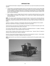
1. On the right side of the combine adapter, locate
hydraulic pump (A).
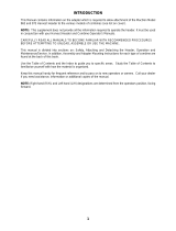
2. Disconnect check valve fitting (A) from check
valve (B), which is attached to the pump (not
shown in illustration).
3. Detach hose (C) from check valve fitting (A), and
then discard fitting.
Figure 2: Check Valve with Original Elbow Fitting
Figure 1: Hydraulic Pump on Right Side of Combine Adapter

871 and 872 Combine Adapters
FLOW CONTROL VALVE KIT (MD #294401)
INSTALLATION INSTRUCTIONS
214468 Revision A Page 4 of 5
4. Install new 90° elbow fitting (A) (MD #252837)
and inline check valve fitting (B) (MD #252838)
onto check valve (C) as shown.
IMPORTANT: Flow direction of the inline check
valve fitting (B) is very important. The arrow
stamped on the fitting must point away from the
90° elbow fitting (A). If installed backwards,
damage may occur.
5. Attach the hose to the inline check valve
fitting (B).
6. On the front left side of the adapter frame, locate
valve (A).
NOTE: Some parts have been removed from the
illustration for clarity.
Figure 3: Check Valve with New Fittings
Figure 4: Valve on Front Left Side of Adapter Frame

871 and 872 Combine Adapters
FLOW CONTROL VALVE KIT (MD #294401)
INSTALLATION INSTRUCTIONS
214468 Revision A Page 5 of 5
7. Detach all hoses and fittings from the valve, and
then discard the valve.
NOTE: Make sure you remember where each of
the hoses and fittings was attached. You will
need to reconnect them to the new valve.
8. Replace the valve with the new valve
(MD #123030) provided in the kit.
9. Reattach all hoses and fittings to the new valve.
Figure 5: Valve Block Hose Connections
/