Page is loading ...

Sure Cross
®
DXM150-Bx and DXM1500-Bx
Wireless Controllers
Instruction Manual
Original Instructions
190038 Rev. D
12 August 2019
©
Banner Engineering Corp. All rights reserved
190038

Contents
1 System Overview .............................................................................................................................................................5
1.1 System Overview for the B1 Models ............................................................................................................................................... 5
1.2 System Overview for the B2 Models ............................................................................................................................................... 6
1.3 Hardware Overview ......................................................................................................................................................................... 7
1.4 DXM
Configuration Software ........................................................................................................................................................... 9
1.5 DXM Automation Protocols ............................................................................................................................................................. 9
1.6 DXM Modbus Overview ................................................................................................................................................................. 10
2 Quick Start Guide .......................................................................................................................................................... 12
2.1 Device Setup .................................................................................................................................................................................12
2.1.1 Apply Power to the Controller ............................................................................................................................................... 12
2.1.2 Binding and Conducting a Site Survey with the ISM Radio ..................................................................................................12
2.1.3 Set the IP Address ................................................................................................................................................................ 14
2.2
Configuration Instructions .............................................................................................................................................................14
2.2.1
Configuring the Controller ...................................................................................................................................................... 14
2.2.2 Configuration Example: Reading Registers on a Modbus Slave Device .............................................................................. 14
3 ISM Radio Board (Slave ID 1) ....................................................................................................................................... 17
3.1 MultiHop Radio DIP Switches ........................................................................................................................................................17
3.1.1 Application Mode ................................................................................................................................................................... 18
3.1.2 Baud Rate and Parity ............................................................................................................................................................. 18
3.1.3 Disable Serial ..........................................................................................................................................................................18
3.1.4 Transmit Power Levels/Frame Size ........................................................................................................................................19
3.2 DIP Switch Settings for the Gateway Radio Board Module .......................................................................................................... 19
4 Processor Boards ..........................................................................................................................................................20
4.1 Processor Board for the DXM1x0 Models ..................................................................................................................................... 20
4.2 Processor Board for the DXM1x00 Models ................................................................................................................................... 20
4.3 DIP Switch Settings for the Processor Board ...............................................................................................................................21
4.4 Ethernet .........................................................................................................................................................................................21
4.5 USB ...............................................................................................................................................................................................22
5 I/O Base Boards ............................................................................................................................................................ 23
5.1 Board Connections for the B1 Models .......................................................................................................................................... 23
5.2 Board Connections for the B2 Models .......................................................................................................................................... 24
5.3 DIP Switches for the I/O Board ......................................................................................................................................................25
5.4 Setting the Modbus Slave ID on the I/O Base Board .................................................................................................................... 25
5.4.1 DXM-Bx Wireless Controller Models ......................................................................................................................................25
5.4.2 Setting the DXM I/O Board Modbus Slave ID using Modbus Registers ................................................................................ 26
5.5 I/O Board Jumpers ....................................................................................................................................................................... 26
5.6 Applying Power to the B1 Models ................................................................................................................................................. 26
5.7 Applying Power to the B2 or S2 Models ........................................................................................................................................27
5.8 Connecting a Battery ..................................................................................................................................................................... 27
5.9 Supplying Power from a Solar Panel ............................................................................................................................................. 27
5.10 Connecting the Communication Pins ......................................................................................................................................... 27
5.11 Modbus RTU Master and Slave Ports ......................................................................................................................................... 28
5.11.1 Modbus Master and Slave Port Settings ............................................................................................................................ 28
5.11.2 DXM Modbus Slave Port ID ................................................................................................................................................ 29
5.12 Inputs and Outputs ...................................................................................................................................................................... 29
5.12.1 Universal Inputs ....................................................................................................................................................................29
5.12.2 Isolated Discrete Inputs .......................................................................................................................................................31
5.12.3 NMOS Outputs ....................................................................................................................................................................31
5.12.4 PNP and NPN Outputs ........................................................................................................................................................31
5.12.5 Analog Outputs (DAC) ......................................................................................................................................................... 32
6 Cellular Modem Boards .................................................................................................................................................33
6.1 Cellular Modem Board ...................................................................................................................................................................33
6.2 Cellular Power Requirements ....................................................................................................................................................... 33
6.3 Using the DXM Cellular Modem .................................................................................................................................................... 33
6.4 Activating a Cellular Modem ..........................................................................................................................................................33
6.4.1 Install the Cellular Modem ......................................................................................................................................................34
6.4.2 Activate a 3G GSM Cellular Plan ...........................................................................................................................................35
6.4.3 Activate a Verizon 4G LTE Cellular Plan ................................................................................................................................35
6.4.4
Configure the DXM Controller for a Cellular Modem ............................................................................................................ 35
6.5 Accessing the DXM Using SMS .................................................................................................................................................... 36
7 LCD and Menu System ................................................................................................................................................. 38
7.1 Registers .......................................................................................................................................................................................38
7.2 Push ..............................................................................................................................................................................................38
Sure Cross
®
DXM150-Bx and DXM1500-Bx Wireless Controllers

7.3 ISM Radio ..................................................................................................................................................................................... 39
7.4 I/O Board ...................................................................................................................................................................................... 39
7.5 System Config ............................................................................................................................................................................... 41
7.5.1 ISM Radio ..............................................................................................................................................................................41
7.5.2 I/O Board ...............................................................................................................................................................................42
7.5.3 Ethernet ................................................................................................................................................................................. 43
7.5.4 Provision Cell .........................................................................................................................................................................43
7.5.5 DXM Modbus ID .................................................................................................................................................................... 43
7.5.6 LCD Contrast .........................................................................................................................................................................43
7.5.7 Reset ..................................................................................................................................................................................... 43
7.6 System Info ...................................................................................................................................................................................44
7.7 Display Lock ................................................................................................................................................................................. 45
8
Configuration Instructions ............................................................................................................................................ 46
8.1 DXM Configuration Software ......................................................................................................................................................... 46
8.2 Register Flow and
Configuration .................................................................................................................................................. 46
8.2.1 Basic Approach to Configuration .......................................................................................................................................... 46
8.2.2 Troubleshooting a Configuration ...........................................................................................................................................47
8.2.3 Saving and Loading
Configuration Files ............................................................................................................................... 47
8.2.4 Uploading or Downloading Configuration Files .....................................................................................................................47
8.3 Scheduler ......................................................................................................................................................................................47
8.3.1 Create a Weekly Event .......................................................................................................................................................... 48
8.3.2 Create a One-Time Event ......................................................................................................................................................48
8.3.3 Create a Holiday Event ..........................................................................................................................................................49
8.4 Authentication Setup .................................................................................................................................................................... 49
8.4.1 Set the Controller to use Authentication ............................................................................................................................... 49
8.4.2 Set the Web Services to Use Authentication ........................................................................................................................ 49
8.4.3 Mail Server Authentication .................................................................................................................................................... 50
8.4.4 Controller
Configuration Authentication ................................................................................................................................51
8.5 Setting Up EtherNet/IP
™
.............................................................................................................................................................. 51
8.5.1
Configuring the Controller ..................................................................................................................................................... 51
8.5.2
Configuring the Host PLC ..................................................................................................................................................... 52
8.6 Setting up Email and Text Messaging .......................................................................................................................................... 52
8.6.1 Define the Network Interface Settings .................................................................................................................................. 53
8.6.2
Configure your Ethernet Connection .....................................................................................................................................53
8.6.3 Configure your Cellular Connection ...................................................................................................................................... 54
8.6.4 Set the Email and Messaging Parameters ............................................................................................................................ 54
8.6.5
Define Threshold Rules for Email .......................................................................................................................................... 55
8.6.6
Define Log File Parameters for Emailing Log Files ................................................................................................................55
8.7 Ethernet and Cellular Push Retries ............................................................................................................................................... 56
8.7.1 Ethernet Push Retries ............................................................................................................................................................56
8.7.2 Cellular Push Retries ............................................................................................................................................................. 56
8.7.3 Event/Action Rule or Log File Push Retries .......................................................................................................................... 57
8.7.4 Email and Text Message Push Retries ..................................................................................................................................57
9 Additional Information .................................................................................................................................................. 58
9.1 Working with Modbus Devices ...................................................................................................................................................... 58
9.1.1 Assigning Modbus Slave IDs .................................................................................................................................................58
9.1.2 Wireless and Wired Devices ..................................................................................................................................................59
9.1.3 Modbus Communication Timeouts ....................................................................................................................................... 59
9.1.4 Modbus TCP Client ............................................................................................................................................................... 61
9.2 Modbus Register Summary .......................................................................................................................................................... 61
9.2.1 DXM Modbus Registers ........................................................................................................................................................ 61
9.2.2 Modbus Registers for the MultiHop Radio Board Module .....................................................................................................61
9.2.3 Modbus Registers for the Gateway Radio Board Module ..................................................................................................... 61
9.2.4 Internal Local Registers (Slave ID 199) for the DXM100 and DXM150 .................................................................................. 65
9.2.5 Internal Local Registers (Slave ID 199) for the DXM700, DXM1000, and DXM1500 ..............................................................67
9.2.6 Modbus Registers for the B1 and S1 I/O Board .................................................................................................................... 71
9.2.7 Modbus Registers for the B2 and S2 I/O Board .................................................................................................................... 71
9.2.8 Modbus
Configuration Registers for the Discrete and Universal Inputs ...............................................................................72
9.2.9 Modbus
Configuration Registers for Isolated Discrete Inputs .............................................................................................. 72
9.2.10 Modbus Configuration Registers for the Analog Output .....................................................................................................73
9.2.11 Modbus
Configuration Registers for the I/O (Definitions) .................................................................................................... 74
9.2.12 Modbus Configuration Registers for Power ........................................................................................................................75
9.2.13 Modbus Registers for the LCD Board (Slave ID 201) ..........................................................................................................75
9.3 Using the Auxiliary Power Outputs ............................................................................................................................................... 77
9.4 Working with Solar Power ............................................................................................................................................................ 77
9.4.1 Setting the DXM for Solar Power .......................................................................................................................................... 77
9.4.2 Solar Components ................................................................................................................................................................ 77
9.4.3 Recommended Solar
Configurations .................................................................................................................................... 78
9.4.4 Monitoring Solar Operation ................................................................................................................................................... 79
9.5 Clear the Password for the DXM100 and DXM150 Models Only ................................................................................................. 79
Sure Cross
®
DXM150-Bx and DXM1500-Bx Wireless Controllers

9.6 Clear the Password on DXM700-Bx, DXM1000-Bx, or DXM1500-Bx Models .............................................................................80
10 DXM150 Dimensions .................................................................................................................................................. 81
11 Accessories ................................................................................................................................................................. 82
12 Product Support and Maintenance ............................................................................................................................ 83
12.1 File System and Archive Process ............................................................................................................................................... 83
12.2 Troubleshooting .......................................................................................................................................................................... 84
12.2.1 Restoring Factory Default Settings for the I/O Base Board ................................................................................................. 84
12.2.2 Updating the DXM Processor Firmware ..............................................................................................................................84
12.2.3 Troubleshooting Issues ....................................................................................................................................................... 88
12.2.4 Modbus Operation .............................................................................................................................................................. 88
12.3 DXM150 Documentation List ......................................................................................................................................................89
12.4 DXM Support Policy ................................................................................................................................................................... 89
12.4.1 Firmware Updates ............................................................................................................................................................... 89
12.4.2 Website Information ............................................................................................................................................................ 89
12.4.3 Feature Requests ................................................................................................................................................................ 89
12.4.4 Potential DXM Issues .......................................................................................................................................................... 89
12.4.5 DXM Security .......................................................................................................................................................................90
12.5 Contact Us ...................................................................................................................................................................................90
12.6 Warnings ......................................................................................................................................................................................90
12.7 Banner Engineering Corp. Limited Warranty .............................................................................................................................. 90
12.8 Glossary of Wireless Terminology ............................................................................................................................................... 90
Sure Cross
®
DXM150-Bx and DXM1500-Bx Wireless Controllers

1 System Overview
1.1 System Overview for the B1 Models
Banner's DXM Logic Controller integrates Banner's wireless radio, cellular connectivity, and local I/O to provide a platform
for the Industrial Internet of Things (IIoT). Various combinations of I/O and connectivity are available based on the different
models.
Connectivity
Cellular
Sure Cross Radios
Ethernet
USB
RS-485 Master
RS-485 Slave
SDI-12
User Interface
LCD Screen
LED Indicators
I/O
Universal Inputs
Discrete Outputs
Courtesy Power
Switch Power
Isolated Inputs
Relay Outputs
Logic Controller
Action Rules
Programming Language
Scheduler
Push to the Cloud
Data Logging
SMS and Email
SMS Control
Inputs/Outputs—On-board universal and programmable I/O ports connect to local sensors, indicators, and control
equipment.
• Universal Inputs
• Discrete outputs
• Courtesy power
• Switch power
• Isolated inputs
• Relay outputs
• Battery backup
• Solar controller
Connectivity—The DXM's wired and wireless connectivity options make it easy to share data between local and remote
equipment. The cellular modem option eliminates the need for IT infrastructures to connect remote equipment for sensing
and control. The integrated Sure Cross
®
wireless radio enables Modbus connectivity to remote sensors, indicators, and
control equipment.
Wired Connectivity
Ethernet: Modbus/TCP or Ethernet/IP
Field Bus: Modbus RS-485 Master/Slave or Controller Area
Network (CAN)
Wireless Connectivity
Sure Cross Wireless Radio: DX80 900 MHz, DX80 2.4 GHz,
MultiHop 900 MHz, or MultiHop 2.4 GHz
Cellular modem: CDMA (Verizon), GSM 3G, LTE (Verizon)
Logic Controller—Program the DXM's logic controller using action rules and/or ScriptBasic language, which can execute
concurrently. The control functions allow freedom when creating custom sensing and control sequences. The logic
controller supports the Modbus protocol standards for data management, ensuring seamless integration with existing
automation systems.
Action Rules
Supports simple logic, arithmetic and thresholding
Use for low complexity solutions
SMS text message
Notifications
E-mail Notifications
Push data on conditions
Text Programming Language
ScriptBasic
Use when Action Rules cannot supply a solution
Scheduler
Time/calendar-based events
Astronomical clock
Data Logging
Cyclic Data/Event logging
E-mail log files
SMS Commanding
Read/Write Local Registers
Upload data to the cloud-based data service
Reboot controller
Sure Cross
®
DXM150-Bx and DXM1500-Bx Wireless Controllers
www.bannerengineering.com - Tel: + 1 888 373 6767 5

User Interface—A simple user interface consists of an LCD screen and four LED indicators. Use the LCD to access system
status and setup, view user selectable events or data, and to bind and perform site surveys for Sure Cross radios. Configure
the user programmable LEDs to indicate the status of the DXM, processes, or equipment.
User programmable LCD
Binding Sure Cross Radios
Conducting a Site Survey
Viewing sensor information
Viewing the system's status
User Defined LED indicators
1.2 System Overview for the B2 Models
Banner's DXM Logic Controller integrates Banner's wireless radio, cellular connectivity, and local I/O to provide a platform
for the Industrial Internet of Things (IIoT).
Connectivity
Cellular
Sure Cross Radios
Ethernet
USB
RS-485 Master
RS-485 Slave
User Interface
LCD Screen
LED Indicators
I/O
Universal Inputs
PNP/NPN Outputs
Analog Outputs
Isolated Inputs
Courtesy Power
Logic Controller
Action Rules
Programming Language
Scheduler
Push to the Cloud
Data Logging
SMS and Email
SMS Control
Inputs/Outputs—On-board universal and programmable I/O ports connect to local sensors, indicators, and control
equipment.
• Universal Inputs
• Analog outputs
• PNP/NPN outputs
• Isolated inputs
• Courtesy power
• Battery backup
• Solar controller
Connectivity—The DXM's wired and wireless connectivity options make it easy to share data between local and remote
equipment. The cellular modem option eliminates the need for IT infrastructures to connect remote equipment for sensing
and control. The integrated Sure Cross
®
wireless radio enables Modbus connectivity to remote sensors, indicators, and
control equipment.
Wired Connectivity
Ethernet: Modbus/TCP or Ethernet/IP
Field Bus: Modbus RS-485 Master/Slave or Controller Area
Network (CAN)
Wireless Connectivity
Sure Cross Wireless Radio: DX80 900 MHz, DX80 2.4 GHz,
MultiHop 900 MHz, or MultiHop 2.4 GHz
Cellular modem: CDMA (Verizon), GSM 3G, LTE (Verizon)
Logic Controller—Program the DXM's logic controller using action rules and/or ScriptBasic language, which can execute
concurrently. The control functions allow freedom when creating custom sensing and control sequences. The logic
controller supports the Modbus protocol standards for data management, ensuring seamless integration with existing
automation systems.
Sure Cross
®
DXM150-Bx and DXM1500-Bx Wireless Controllers
6 www.bannerengineering.com - Tel: + 1 888 373 6767

Action Rules
Supports simple logic, arithmetic and thresholding
Use for low complexity solutions
SMS text message
Notifications
E-mail Notifications
Push data on conditions
Text Programming Language
ScriptBasic
Use when Action Rules cannot supply a solution
Scheduler
Time/calendar-based events
Astronomical clock
Data Logging
Cyclic Data/Event logging
E-mail log files
SMS Commanding
Read/Write Local Registers
Upload data to the cloud-based data service
Reboot controller
User Interface—A simple user interface consists of an LCD screen and four LED indicators. Use the LCD to access system
status and setup, view user selectable events or data, and to bind and perform site surveys for Sure Cross radios.
Configure
the user programmable LEDs to indicate the status of the DXM, processes, or equipment.
User programmable LCD
Binding Sure Cross radios
Conducting a Site Survey
Viewing sensor information
Viewing the system's status
User Defined LED indicators
1.3 Hardware Overview
The DXM can have several different configurations. The DXM has a model number label on the housing. Use the model
number and model table to identify which boards are included in the your controller.
B1 =
Radio
Configuration
B1
Base
DXM150-
R1
Blank = None
R1 = 900 MHz, 1 W PE5 Performance Radio (North America)
R2 = 900 MHz, 1W HE5 MultiHop Data Radio (North America)
R3 = 2.4 GHz, 65 mW PE5 Performance Radio (Worldwide)
R4 = 2.4 GHz, 65 mW HE5 MultiHop Data Radio (Worldwide)
R5 = 900 MHz, 65 mW HE5L MultiHop Data Radio (Used for M-GAGE networks)
R8 = 900 MHz, Performance Radios approved for Australia/New Zealand
R9 = 900 MHz, MultiHop Radio approved for Australia/New Zealand
Modbus controller designed for applications with
high I/O count, isolated inputs or integrated relays
Power: 12−30 V dc/Solar/Battery
Comms: RS-485 and RS-232 / CAN or secondary RS-485
Inputs: (2) Isolated discrete, (8) Universal
Outputs: (2) Relay, (4) NMOS, (2) Analog
Power Out: (2) Jumper selectable between 2.7 V or battery,
4.2 V or incoming power
B1 =
Radio
Configuration
B1
Base
DXM1500-
R1
Modbus controller for data aggregation of sensors
and wireless networks
Power: 12−30 V dc / Solar / Battery
Comms: RS-485 master/slave
Inputs: (4) universal, (2) isolated
Outputs: (4) NMOS, (2) analog (0–10 V or 4–20 mA), (2) relay
(1) 5 V courtesy power
Blank = None
R1 = 900 MHz, 1 W PE5 Performance Radio (North America)
R2 = 900 MHz, 1 W HE5 MultiHop Data Radio (North America)
R3 = 2.4 GHz, 65 mW PE5 Performance Radio (Worldwide)
R4 = 2.4 GHz, 65 mW HE5 MultiHop Data Radio (Worldwide)
R5 = 900 MHz, 65 mW HE5L MultiHop Data Radio (Used for M-GAGE networks)
R8 = 900 MHz, Performance Radios approved for Australia/New Zealand
R9 = 900 MHz, MultiHop Radio approved for Australia/New Zealand
Sure Cross
®
DXM150-Bx and DXM1500-Bx Wireless Controllers
www.bannerengineering.com - Tel: + 1 888 373 6767 7

B2 =
Radio
Configuration
B2
Base
DXM150-
R1
Blank = None
R1 = 900 MHz, 1 W PE5 Performance Radio (North America)
R2 = 900 MHz, 1W HE5 MultiHop Data Radio (North America)
R3 = 2.4 GHz, 65 mW PE5 Performance Radio (Worldwide)
R4 = 2.4 GHz, 65 mW HE5 MultiHop Data Radio (Worldwide)
R5 = 900 MHz, 65 mW HE5L MultiHop Data Radio (Used for M-GAGE networks)
R8 = 900 MHz, Performance Radios approved for Australia/New Zealand
R9 = 900 MHz, MultiHop Radio approved for Australia/New Zealand
Modbus controller for high I/O count applications
Power: 12-30 V dc/Solar/Battery
Comms: RS-485 and RS-232 w/flow control or secondary RS-485
Inputs: (2) Isolated discrete, (8) Universal
Outputs: (8) PNP/NPN Selectable, (2) Analog
Power Out: (2) Courtesy power out; (2) jumper selectable
between 2.7 V or battery, 4.2 V or incoming power
Not all combinations of base boards and radios are supported.
Important:
• Electrostatic discharge (ESD) sensitive device
• ESD can damage the device. Damage from inappropriate handling is not covered by warranty.
• Use proper handling procedures to prevent ESD damage. Proper handling procedures include
leaving devices in their anti-static packaging until ready for use; wearing anti-static wrist straps;
and assembling units on a grounded, static-dissipative surface.
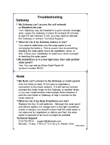
DXM150 I/O
Base Board
MultiHop or Gateway
Radio Board
Processor Board
Cellular Radio Board
The DXM150 I/O Base Board is shown. The DXM1500 I/O Base Board is similar.
Sure Cross
®
DXM150-Bx and DXM1500-Bx Wireless Controllers
8 www.bannerengineering.com - Tel: + 1 888 373 6767

I/O Base Board—The DXM I/O base board provides connections for all inputs, outputs and power. The I/O base board
contains a 12 V solar controller that accepts connections to a solar panel and sealed lead acid (SLA) battery. The battery
connection can also be used with line power to provide a battery backup in case of line power outages.
ISM Radio—The ISM radio, either a MultiHop or DX80 Gateway,
fits on the I/O base board in the parallel sockets. Install the
ISM radio so the U.FL antenna connection is to the side with the SMA antenna connectors. Connect the U.FL cable from
the ISM radio U.FL to the right side U.FL connector. The ISM radio boards are available with either a 900 MHz radio (North
America) or a 2.4 GHz radio (world-wide).
Processor—The processor board plugs into the base board using the two 20 pin socket connectors. The board sits above
the ISM radio socket and held by the base board standoffs. Position the processor board so the USB and RJ45 Ethernet
connection is to the front, away from the SMA antenna connections.
Cellular Modem (Optional)—The optional cellular modem (purchased separately) board plugs into the processor board with
the U.FL antenna connection to the left. Attach the antenna cable from the cellular modem to the left U.FL connection on
the base board.
In some DXM models, the cellular modem may be replaced with an ISM radio. In this configuration, position the top ISM
radio antenna connection to the left of the SMA antenna connector.
LCD (Display) Board—The top housing contains the LCD board. The display board is connected to the base board using a
ribbon cable with a 20 pin connector.
1.4 DXM Configuration Software
Download the latest version of all configuration software from
http://www.bannerengineering.com
. For more information on
using the DXM Configuration Software, refer to the instruction manual (p/n
209933
).
The DXM Configuration Software configures the DXM by creating an
XML file that is transferred to the DXM using a USB or Ethernet
connection. The DXM can also receive the XML configuration file from
a Web server using a cellular or Ethernet connection.
This
configuration file governs all aspects of the DXM operation.
The wireless network devices are a separate configurable system. Use
the DX80 User Configuration Software to configure the internal DX80
wireless Gateway and the attached wireless Nodes. Use the MultiHop
Configuration Software if the internal radio is a MultiHop device.
All tools can be connected to the DXM using a USB cable or an
Ethernet connection.
USB
Ethernet
DXM Configuration Software
Local Registers
Register
View Utility
System
Settings
Register Mapping
Scheduler
Action Rules
Script Basic
XML Config File
Figure 1. Overview of the DXM Configuration Software
features
1.5 DXM Automation Protocols
The DXM supports the following automation protocols.
Sure Cross
®
DXM150-Bx and DXM1500-Bx Wireless Controllers
www.bannerengineering.com - Tel: + 1 888 373 6767 9

Modbus RTU
The DXM manages two separate physical ports running the Modbus RTU protocol. The DXM is the Modbus Master
when operating the Modbus master RTU port. The DXM uses the master Modbus RTU bus to communicate with
locally connected Modbus devices or uses the Banner wireless radio to communicate with remote Modbus
devices.
The other Modbus RTU port is used by a host system to access the DXM as a slave device. The slave Modbus RTU
port allows access all the internal registers concurrently with the master RTU port. Set the slave Modbus ID using
the LCD menu: SYSTEM CONFIG > DXM Modbus ID.
By default, the Modbus RTU ports are active.
Configure the port parameters using the DXM Configuration
Software.
Modbus TCP/IP
A host system acting as a Modbus master can access the DXM using the Modbus TCP/IP protocol over Ethernet.
Standard Modbus port 502 is used by the DXM for all Modbus TCP/IP requests.
All internal registers are available to the host system concurrently with Modbus RTU.
By default, Modbus TCP/IP is active.
Configure the DXM using Modbus TCP rules in the DXM Configuration
Software.
EtherNet/IP
™
The Ethernet port is actively running EtherNet/IP. From the factory the DXM is
configured to read and write
registers on DX80 wireless devices 1 through 16. Custom configurations can be set using the DXM Configuration
Software.
By default, EtherNet/IP is active.
1.6 DXM Modbus Overview
The DXM uses internal 32-bit registers to store information. The processor's internal Local Registers serve as the main
global pool of registers and are used as the common data exchange mechanism. External Modbus device registers can be
read into the Local Registers or written from the local data registers.
The DXM, as a Modbus master or slave, exchanges data using the Local Registers. Modbus over Ethernet (Modbus/TCP)
uses the Local Registers as the accessible register data.
Using Action, Read/Write, and Threshold Rules allows you to manipulate the processor's Local Registers. The ScriptBasic
programming capabilities extends the use of Local Registers with variables to create a
flexible programming solution for
more complex applications.
The processor's Local Registers are divided into three different types: integer,
floating point, and non-volatile. When using
Local Registers internally, the user can store 32-bit numbers. Using Local Registers with external Modbus devices follows
the Modbus standard of a 16-bit holding register. Local Registers are accessible as Modbus ID 199.
Accessing the I/O base board and the LCD follows the same communication as an external Modbus device. Each device
has an ID number to uniquely identify itself. The I/O base board is Modbus ID 200 and the LCD is Modbus ID 201.
Sure Cross
®
DXM150-Bx and DXM1500-Bx Wireless Controllers
10 www.bannerengineering.com - Tel: + 1 888 373 6767

Local Registers
(Modbus ID 199)
DXM Processor
Modbus Data
Traffic Control
Local Registers
Non-Volatile
Local Registers
Float
Local Registers
Integer
Gateway or MultiHop
(Slave ID 1)
LCD (Slave ID 201)
I/O Base Board
(Slave ID 200)
Action Rules
Read/Write Rules
ScriptBasic
Sure Cross
®
DXM150-Bx and DXM1500-Bx Wireless Controllers
www.bannerengineering.com - Tel: + 1 888 373 6767 11

2 Quick Start Guide
2.1 Device Setup
2.1.1 Apply Power to the Controller
Follow these instructions to apply 12–30 V dc power to the controller using a wall plug.
Equipment used:
• DXM-Bx Wireless Controller
MQDMC-501 0.3 m (1 ft) cordset with a 5-pin M12/Euro-style quick disconnect
fitting
PS24W Wall plug power supply; 24 V dc, 1 A
Important:
• Never operate a 1 Watt radio without connecting an antenna
• Operating 1 Watt radios without an antenna connected will damage the radio circuitry.
• To avoid damaging the radio circuitry, never apply power to a Sure Cross
®
Performance or Sure
Cross MultiHop (1 Watt) radio without an antenna connected.
1. Connect the brown wire from the MQDMC-501 cordset to the DXM's PW (+ power) terminal.
2. Connect the blue wire from the MQDMC-501 cordset to the DXM's GD (- ground) terminal.
3. Connect the PS24W power supply to the MQDMC-501 cordset.
4. Plug in the PSD24W wall plug power supply.
2.1.2 Binding and Conducting a Site Survey with the ISM Radio
The DXM internal ISM radio will either be a MultiHop master radio or a DX80 Gateway radio. Before the ISM radio can
communicate, the ISM radios within the DXM must be bound to the other radios in the wireless network.
Use the DXM LCD menu to bind radios to the internal ISM radio.
Some
configurations of the DXM Controller will make it difficult to run binding or site survey. If you are having trouble
accessing these features, disable the XML configuration file using DIP switch 4 on the processor board or load in a blank
XML
file.
Bind a DX80 Node to a DXM Gateway and Assign the Node Address
Before beginning the binding procedure, apply power to all the devices. Separate radios by 2 meters when running the
binding procedure. Put only one DXM Gateway into binding mode at a time to prevent binding to the wrong Gateway.
Binding Nodes to a Gateway ensures the Nodes only exchange data with the Gateway they are bound to. After a Gateway
enters binding mode, the Gateway automatically generates and transmits a unique extended addressing (XADR), or binding,
code to all Nodes within range that are also in binding mode. The extended addressing (binding) code
defines the network,
and all radios within a network must use the same code.
1. Enter binding mode on the DXM radio:
a) Use the arrow keys to select the ISM Radio menu on the LCD and press ENTER.
b) Highlight the Binding menu and press ENTER.
2. Assign the Node address to the Node.
• For Nodes without rotary dials: Use the DXM arrow keys to select the Node address to assign to the DX80 Node
about to enter binding mode. The DXM assigns this Node address to the next Node that enters binding mode.
Only bind one Node at a time.
• For Nodes with rotary dials: Use the Node's rotary dials to assign a valid decimal Node Address (between 01
and 47). The left rotary dial represents the tens digit (0 through 4) and the right dial represents the ones digit (0
through 9) of the Node Address.
3. Start binding mode on the DXM radio by pressing ENTER on the DXM radio.
4. Enter binding mode on the DX80 Node.
• For housed radios, triple-click button 2.
• For board-level radios, triple-click the button.
• For Nodes without buttons, refer to the Node's datasheet for instructions on entering binding mode.
Sure Cross
®
DXM150-Bx and DXM1500-Bx Wireless Controllers
12 www.bannerengineering.com - Tel: + 1 888 373 6767

The left and right red LEDs flash alternately and the Node searches for a Gateway in binding mode. After the Node
binds, the LEDs stay solid momentarily, then they flash together four times. The Node automatically exits binding
mode.
5. Label the Node with the assigned address number for future reference.
6. Press BACK on the DXM to exit binding mode for that specific Node address.
7. Repeat steps 2 through 5, for as many DX80 Nodes as are needed for your network.
8. When you are finished binding, press BACK on the DXM until you return to the main menu.
Bind a MultiHop Radio to a DXM and Assign the Device ID
Before beginning the binding procedure, apply power to all the devices. Separate radios by 2 meters when running binding
procedure. Put only one DXM MultiHop master radio into binding mode at a time to prevent binding the slave radios to the
wrong master radio.
Binding MultiHop radios ensures all MultiHop radios within a network communicate only with other radios within the same
network. The MultiHop radio master automatically generates a unique binding code when the radio master enters binding
mode. This code is then transmitted to all radios within range that are also in binding mode. After a repeater/slave is bound,
the repeater/slave radio accepts data only from the master to which it is bound. The binding code
defines the network, and
all radios within a network must use the same binding code.
1. Enter binding mode on the DXM radio:
a) Use the arrow keys select the ISM Radio menu on the LCD and press ENTER.
b) Highlight the Binding menu and press ENTER.
2. Assign the device address to the repeater or slave radios.
• For MultiHop radios without rotary dials: Use the DXM arrow keys to select the device ID to assign to the
MultiHop radio about to enter binding mode. The DXM assigns this device ID to the next radio that enters
binding mode. Only bind one slave radio at a time.
• For MultiHop radios with rotary dials: Use the repeater or slave's rotary dials to assign a valid decimal device ID
(11 through 60). The left rotary dial represents the tens digit (1 through 6) and the right dial represents the ones
digit (0 through 9) of the device ID.
3. Start binding mode on the DXM radio by pressing ENTER on the DXM radio.
4. After entering binding mode on the DXM, put the MultiHop repeater or slave radio into binding mode.
• For housed radios, triple-click button 2.
• For board-level radios, triple-click the button.
• For radios without buttons, refer to the radio's datasheet for instructions on entering binding mode.
After binding is completed, the MultiHop slave automatically exits binding mode and begins operation.
5. Press BACK on the DXM to exit binding mode for that
specific device address.
6. Label the MultiHop slave radio with the assigned address number for future reference.
7. Repeat steps 2 through 6, changing the device address for as many MultiHop slaves as are needed for your
network.
8. When you are
finished binding, press BACK on the DXM until you return to the main menu.
All radio devices begin to form the network after the master data radio exits binding mode.
Conduct a Site Survey
Although the MultiHop and DX80 devices are architecturally different, the site survey process is similar when conducted
from the DXM LCD menu.
Conducting a site survey, also known as a radio signal strength indication (RSSI), analyzes the radio communications link
between the Gateway (or master radio) and any Node (or slave radio) within the network by analyzing the radio signal
strength of received data packets and reporting the number of missed packets that required a retry.
For a DX80 network, the Gateway controls the site survey and the results display on the LCD. Running a site survey on a
DX80 network does not affect the throughput of the DX80 network. The DX80 Gateway-Node system can run a site survey
analysis while the network is operational.
For a MulitHop network, the master device passes the site survey request to the intended Modbus slave device. The Site
Survey runs and the results display on the LCD. Running a site survey on a MultiHop network stops all network
traffic to
that device.
1. From the ISM Radio menu, use the down arrow to highlight the Site Survey menu. Press ENTER.
2. Use the Up or Down arrows to select the Node number (DX80 network) or Modbus Slave ID (MultiHop network).
Press ENTER to run the site survey with that Node or slave.
The site survey results display as green, yellow, red, and missed packets. Green indicates the highest signal strength, then
yellow, and red. Missed packets were not received.
Sure Cross
®
DXM150-Bx and DXM1500-Bx Wireless Controllers
www.bannerengineering.com - Tel: + 1 888 373 6767 13

2.1.3 Set the IP Address
Change the IP address of the DXM-B1R1 to connect to a Modbus TCP/IP or Ethernet/IP host controller.
Equipment needed:
• DXM-B1R1 Wireless Controller
There are two ways to set the IP address: using the DXM's LCD menu or using the DXM Configuration Software to change
the XML
file.
IP addresses entered into the LCD menu system override the IP addresses in the XML configuration files. To use the IP
addresses set in the XML
configuration file, clear the IP addresses from the menu system.
1. On the DXM, use the arrows and move to the System Config menu. Press Enter.
2. Use the arrow keys to select the Ethernet menu. Press Enter.
3. Use the arrow keys to select IP. Press Enter.
The octet of the IP address displays (for example, 192.168.10.1).
4. Use the up and down arrows to change the IP address. Press Enter to move to the next octet.
5. Press Enter on the
final octet to accept the changes.
6. Cycle power to the DXM.
The changes are saved on the DXM and the new IP address will be used.
Use this same procedures to set the subnet mask (SN) and default gateway (GW) to match your network requirements.
2.2 Configuration Instructions
2.2.1 Configuring the Controller
Configure
the DXM using the configuration
software
.
To configure the DXM, connect the DXM's USB or Ethernet port to a
computer.
The DXM
Configuration Software allows the user to define parameters for the
DXM, then saves the configuration in an XML file on the PC.
After the configuration file is saved, upload the XML configuration file to the
DXM for operation.
This quick start guide outlines the basic operations to set up a DXM using the
configuration software. For a more comprehensive explanation of features,
refer to the DXM
Configuration Software Instruction Manual (p/n
209933
).
For a complete list of all associated product documentation, go to
Product
Support and Maintenance
(p. 83).
USB
Ethernet
DXM Configuration Software
Local Registers
Register
View Utility
System
Settings
Register Mapping
Scheduler
Action Rules
Script Basic
XML Config File
Figure 2. DXM Configuration Software
2.2.2 Configuration Example: Reading Registers on a Modbus Slave
Device
The opening page of the DXM Configuration Software displays the Local Registers tab.
The local registers are the main global pool of registers that are defined by the user to store data within the DXM.
The bottom status bar displays the communications status, application status, and the DXM Configuration Software
version.
In this short example, we will configure the DXM to read six registers on an external Modbus Slave device and save the data
into the local registers.
Sure Cross
®
DXM150-Bx and DXM1500-Bx Wireless Controllers
14 www.bannerengineering.com - Tel: + 1 888 373 6767

Step 1: Define the Local Registers
Change the name and parameter settings for each Local Register under the Local Registers in Use screen. You may change
them individually (Edit Register) or in groups (Modify Multiple Registers).
Figure 3. Modify Multiple Registers - Configuration Example
1. Click on the Modify Multiple Registers section of the Local Registers in Use screen. Use this screen to quickly
modify multiple local registers at a time.
2. Select the range of registers to change.
3. Select the fields to change in each local register. In our example, registers one through six will be changed and the
names will be GPS Reg followed by an auto-incremented number. This example will also change the LCD
permissions
flag to Set, then Read to allow the values of the local registers to display on the LCD.
4. Click Modify Registers to apply your changes.
Step 2: Read the Registers
Under Register Mapping, the Read Rules or Write Rules interact with the Local Registers to exchange data with external
Modbus devices.
This example screen shows a read rule created to read six registers (address 1 through 6), from Modbus Slave 4. The
results are stored in the Local Registers 1 through 6.
Figure 4. Read Rules - Configuration Example
1. Go to the Register Mapping > RTU or Modbus TCP > Read Rules tab to define a Modbus read rule.
2. Click Add Read Rule.
3. Click the arrow next to the new rule to display all parameters.
4. Type in a name into the name
field.
5. Select the slave address. In this example, we will read from Slave ID 4.
6. Select the starting register and ending register. In this example, we will read from register 1 through register 6.
7. Select the beginning local register on the DXM.
8. Enter a polling frequency. In this example we have entered
five seconds.
9. If necessary, select the error condition. For this example, if the read function fails after three attempts, the read rule
writes 12345 to the DXM local registers. Notice the list of local register names this read rule is using.
Sure Cross
®
DXM150-Bx and DXM1500-Bx Wireless Controllers
www.bannerengineering.com - Tel: + 1 888 373 6767 15

Step 3: Define the Time Zone and Set the Time Clock
Use the Settings > System screen to define the time zone and daylight saving option. The time zone and DST options are
saved into the configuration file.
Figure 5. Settings > System > Device Time
If you connect the DXM to a computer, click Sync PC Time with Device to set the time on the DXM to match the time of the
computer.
Step 4: Save the
Configuration File
To save your
configuration file:
1. Go to File > Save As.
2. Enter a file name and save the file. The file name cannot contain spaces or special characters.
Step 5: Connect the DXM
1. Connect the DXM to the computer using the USB port.
2. From the Device menu, select Connection Settings.
3. From the dialog box, select the appropriate com port for the DXM
communications.
4. Click Connect to connect to the DXM.
Figure 6. Connection settings pop-up window
Step 6: Send the Configuration File to the DXM
1. From the Device menu, select Send XML Configuration to Device.
2. Select the configuration file to load. The software will have pre-selected the file name you have previously saved.
Important: The software only loads a
file to the DXM. Internal parameter settings that are changed in the
tool but not saved to the file will not be sent to the device.
After the file is selected, the software uploads the file to the DXM. The DXM Configuration Software reboots the controller
after the
configuration file finishes uploading. The new configuration is only read at startup and always requires a reboot or
power cycle to take effect. It will take a few seconds for the DXM to reboot.
Important: If the power cycles to the DXM while the DXM
Configuration Software is connected, close the
USB port from the software and unplug the USB cable. Reconnect the DXM by plugging the USB cable
into the DXM, then select Device > Connection Settings.
The DXM is now running the new configuration. On the DXM's LCD screen, select the Registers menu by clicking the Enter
button with the Registers menu highlighted. The local registers
defined in the configuration tool display.
Sure Cross
®
DXM150-Bx and DXM1500-Bx Wireless Controllers
16 www.bannerengineering.com - Tel: + 1 888 373 6767

3 ISM Radio Board (Slave ID 1)
The ISM embedded radio boards are available in either DX80 MultiHop or DX80 Performance.
1
1
ON
ON
A
D1
B
C
D2
234
234
Figure 7. ISM radio board
Plug the ISM radio into the I/O base board with the U.FL
antenna connector closest to the SMA connectors.
A - Antenna connector
B - Button
C - LED
D1 - DIP switches
D2 - DIP Switches
Button Operation
For DXM models without a LCD display, use the button (B) to bind the ISM radio. For models with a LCD display,
use the ISM menu to bind the radio.
LED Operation
The LED located on the ISM radio module indicates power and communications
traffic.
• Solid green DX80 ISM radio LED: Indicates power.
• Flashing green MultiHop ISM radio LED indicates operation.
• Red and green combined: Communications traffic and binding.
ISM board LED operations also display on the LED on the right side of the I/O base board.
3.1 MultiHop Radio DIP Switches
The DX80 MultiHop architecture creates a tree network with a Master radio and one or more Repeater/Slave devices. The
MultiHop architecture is suited for networks requiring repeater devices to provide extended range or obstacle avoidance.
MultiHop ISM radio devices are
defined with R2, R4, and R5 in the model number.
• DXMxxx-xxR2 - MultiHop 900 MHz
• DXMxxx-xxR4 - MultiHop 2.4 GHz
• DXMxxx-xxR5 - MultiHop 900 MHz, 100 mW
• DXMxxx-xxR9 - MultiHop 900 MHz, (Australia)
Making changes to the baud or parity settings requires that you make the same settings to the Modbus Master
Communications section within the DXM Configuration Software (Settings > General.
Important: Disabling the serial port disables the ISM radio in the DXM. Selecting Transparent mode
causes radio communications to be slower and denies access to device I/O register data.
D1 Switches D2 Switches
Device Settings 1 2 3 4 1 2 3 4
Serial line baud rate 19200 OR User defined receiver
slots
OFF* OFF*
Sure Cross
®
DXM150-Bx and DXM1500-Bx Wireless Controllers
www.bannerengineering.com - Tel: + 1 888 373 6767 17

D1 Switches D2 Switches
Device Settings 1 2 3 4 1 2 3 4
Serial line baud rate 38400 OR 32 receiver slots OFF ON
Serial line baud rate 9600 OR 128 receiver slots ON OFF
Serial line baud rate Custom OR 4 receiver slots ON ON
Parity: None OFF* OFF*
Parity: Even OFF ON
Parity: Odd ON OFF
Disable serial (low power mode) and enable the receiver
slots select for switches 1-2
ON ON
Transmit power
900 MHz radios: 1.00 Watt (30 dBm)
2.4 GHz radios: 0.065 Watts (18 dBm) and 60 ms
frame
OFF
Transmit power
900 MHz radios: 0.25 Watts (24 dBm)
2.4 GHz radios: 0.065 Watts (18 dBm) and 40 ms
frame
ON *
Application mode: Modbus OFF*
Application mode: Transparent ON
MultiHop radio setting: Repeater OFF OFF
MultiHop radio setting: Master OFF ON
MultiHop radio setting: Slave ON OFF
MultiHop radio setting: DXM LCD Menu Control ON * ON *
* Default
configuration
The default settings for D2 DIP switches 1, 3, and 4 are ON. This allows for forcing the device into Master mode and DXM
menu control for the radio power settings.
3.1.1 Application Mode
The MultiHop radio operates in either Modbus mode or transparent mode. Use the internal DIP switches to select the mode
of operation. All MultiHop radios within a wireless network must be in the same mode.
Modbus mode uses the Modbus protocol for routing packets. In Modbus mode, a routing table is stored in each parent
device to optimize the radio
traffic. This allows for point to point communication in a multiple data radio network and
acknowledgement/retry of radio packets. To access a radio's I/O, the radios must be running in Modbus mode.
In transparent application mode, all incoming packets are stored, then broadcast to all connected data radios. The data
communication is packet based and not
specific to any protocol. The application layer is responsible for data integrity. For
one to one data radios it is possible to enable broadcast acknowledgement of the data packets to provide better
throughput. In transparent mode, there is no access to the radio's I/O.
3.1.2 Baud Rate and Parity
The baud rate (bits per second) is the data transmission rate between the device and whatever it is physically wired to. Set
the parity to match the parity of the device you are wired to.
3.1.3 Disable Serial
If the local serial connection is not needed, disable it to reduce the power consumption of a data radio powered from the
solar assembly or from batteries. All radio communications remain operational.
Sure Cross
®
DXM150-Bx and DXM1500-Bx Wireless Controllers
18 www.bannerengineering.com - Tel: + 1 888 373 6767

3.1.4 Transmit Power Levels/Frame Size
The 900 MHz data radios can be operated at 1 watt (30 dBm) or 0.250 watt (24 dBm). For most models, the default transmit
power is 1 watt.
For 2.4 GHz radios, the transmit power is
fixed at 0.065 watt (18 dBm) and DIP switch 5 is used to set the frame timing. The
default position (OFF) sets the frame timing to 60 milliseconds. To increase throughput, set the frame timing to 40
milliseconds.
Prior to date code 15341 and radio firmware version 3.6, the frame timing was 40 ms (OFF) or 20 ms (ON).
3.2 DIP Switch Settings for the Gateway Radio Board Module
The 900 MHz radios transmit at 1 Watt (30 dBm) or 250 mW (24 dBm). While the Performance radios operate in 1 Watt
mode, they cannot communicate with the older 150 mW radios. To communicate with 150 mW radios, operate this radio in
250 mW mode. For 2.4 GHz models, this DIP switch is disabled. The transmit power for 2.4 GHz is
fixed at about 65 mW
EIRP (18 dBm), making the 2.4 GHz Performance models automatically compatible with older 2.4 GHz models.
The DX80 Performance architecture is a star-based architecture with one Gateway radio and 1 to 47 Node devices. The
Nodes communicate with the Gateway in a time slot method that is very predictable. DX80 Performance Gateway ISM radio
devices are
defined with R1, R3, and R8 in the model number.
• DXMxxx-xxR1 - DX80 Performance 900MHz
• DXMxxx-xxR3 - DX80 Performance 2.4GHz
• DXMxxx-xxR8 - DX80 Performance 900MHz (Australia)
Important: To adjust the transmit power on the Gateway radio, Banner recommends using the LCD menu
(System Conf > ISM Radio > RF CNTRL).
DIP Switch Bank D1
DIP Switch 1
OFF * 1 Watt (30 dBm, 900 MHz models only) (default configuration)
ON 250 mW (24 dBm, 900 MHz models only), DX80 compatibility mode
Sure Cross
®
DXM150-Bx and DXM1500-Bx Wireless Controllers
www.bannerengineering.com - Tel: + 1 888 373 6767 19

4 Processor Boards
4.1 Processor Board for the DXM1x0 Models
1
1
4
H
I
A
B
C
D
E
A
F
G
A - Cellular modem connection
B - Force cloud push
C - Boot load jumpers
D - DIP switches
E - Micro SD card
F - LED 1
G - LED 2
H - LED 3
I - LED 4
Button Operation—Use the processor board button (B) or force a cloud push. To force a push to the cloud, press and hold
this button for
five (5) seconds to send an immediate push message from the device (if properly configured).
LED Operation—By default, the four LEDs indicate the following conditions:
• LED 1—Heartbeat, indicates the processor is running
• LED 2—Indicates the cellular modem power cutoff is active; if the incoming power is less than 11.2 V, the cellular
modem is powered down
• LED 3—XML configuration file was rejected; or file load in process; or the second phase of boot loading is in
process (flashing)
• LED 4—ScriptBasic program failed to load; or the beginning phase of boot loading is in process (flashing = in
process, on = complete)
Cellular Modem Connection—Install the cellular modem onto the processor board with the cellular modem's U.FL
connector on the left. The antenna cable will go between the cellular U.FL connector and the left I/O base board U.FL
connector. Always disconnect the power to the device before installing or removing a cellular modem.
4.2 Processor Board for the DXM1x00 Models
1
1
ON
A
A
D
E
B
C
F
A - Cellular modem connection
B - Bootload
C - LED
D - DIP switches
E - Micro SD card
Sure Cross
®
DXM150-Bx and DXM1500-Bx Wireless Controllers
20 www.bannerengineering.com - Tel: + 1 888 373 6767
/