
DXM100 Controller Instruction
M
anual
Instruction Manual
Original Instructions
190037 Rev. A
22 January 2016
190037

Contents
1 DXM Overview
................................................................................................................ 3
1.1 DXM System Overview ...............................................................................................................3
1.2 DXM Automation Protocols ......................................................................................................... 3
1.3 DXM Modbus Overview .............................................................................................................. 4
1.4 DXM Configuration Tool Overview ................................................................................................5
2 DXM Hardware Configuration ......................................................................................... 6
2.1 DXM Hardware Configuration Overview ........................................................................................ 6
2.2 ISM Radio Board (Modbus Slave ID 1) .........................................................................................7
2.3 SAM4 Processor Board ..............................................................................................................8
2.4 I/O Base Board ....................................................................................................................... 10
2.4.1 DIP Switches for the I/O Board ........................................................................................10
2.4.2 I/O Board Jumpers ........................................................................................................10
2.4.3 Setting the Modbus Slave ID on the I/O Base Board ........................................................... 11
2.5 Cellular Modem Board .............................................................................................................12
2.6 DXM100 Dimensions ................................................................................................................12
3 DXM Connections ..........................................................................................................13
3.1 I/O Base Board Connections .................................................................................................... 13
3.2 Applying Power to the DXM100 Controller ...................................................................................14
3.2.1 Supplying Power from 12 to 30 V dc and a Battery Backup ..................................................14
3.2.2 Supplying Power from a Solar Panel ................................................................................. 15
3.3 Connecting the Communication Pins ..........................................................................................15
3.4 Ethernet ................................................................................................................................16
3.5 Modbus Master Port and Slave Port ...........................................................................................16
3.5.1 Modbus Master and Slave Port Settings ............................................................................16
3.5.2 Modbus Slave Port ID ....................................................................................................17
3.6 USB ......................................................................................................................................17
4 Working with Modbus Devices ...................................................................................... 18
4.1 Overview ............................................................................................................................... 18
4.2 Assigning Modbus Slave IDs .....................................................................................................18
4.3 Modbus Operation .................................................................................................................. 19
4.4 Wireless and Wired Devices ..................................................................................................... 19
4.5 Modbus Timeouts ................................................................................................................... 20
5 Configuration Instructions ...........................................................................................22
5.1 Working with Solar Power ........................................................................................................22
5.2 Inputs and Outputs ..................................................................................................................24
5.2.1 Universal Inputs ........................................................................................................... 24
5.2.2 NMOS Outputs ............................................................................................................. 26
5.2.3 Analog (DAC) Outputs ...................................................................................................26
5.3 Scheduler ..............................................................................................................................26
5.4 LCD and Menu System .............................................................................................................28
5.5 Authentication Setup .............................................................................................................. 29
5.6 Register Flow and Configuration ............................................................................................... 31
5.7 DXM Cellular Modem ................................................................................................................32
5.8 Binding and Conducting a Site Survey with the ISM Radio ............................................................33
5.9 Setting Up EtherNet/IP
™
......................................................................................................... 34
5.10 Setting up Email and Text Messaging ...................................................................................... 35
5.11 Ethernet and Cellular Push Retries .......................................................................................... 38
5.12 Accessing the DXM Using SMS .................................................................................................39
5.13 Using the Display LEDs ..........................................................................................................40
6 File System and Archive Process ..................................................................................42
7 DXM Modbus Registers ................................................................................................ 43
7.1 Gateway Performance 1 Watt Radio ...........................................................................................43
7.2 MultiHop 1 Watt Radio ............................................................................................................. 44
7.3 Modbus Registers - Internal Local Registers (Modbus Slave 199) .................................................. 44
7.4 I/O Base Board (Modbus Slave 200) .......................................................................................... 47
7.5 LCD Board (Modbus Slave ID 201) .............................................................................................49
8 Restoring Factory Default Settings .............................................................................. 50
9 Contact Us ................................................................................................................... 51
10 Warnings ................................................................................................................... 52
10.1 Banner Engineering Corp. Limited Warranty ............................................................................. 52
DXM100 Controller Instruction Manual

1 DXM Overview
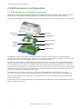
1.1 DXM System Overview
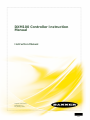
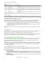
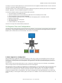
Banner's DXM Logic Controller integrates Banner's wireless radio, cellular connectivity, and local I/O to provide a platform
for the Industrial Internet of Things (IIoT).
Automation
Systems
HMI
PLC
Historian
Cloud
Sensor
Indicator
Machine
Control
Connectivity
Banner Wireless
USB
Ethernet
Cellular
RS-485 Master
RS-485 Slave
User Interface
LCD Screen
LED Indicators
I/O
4 to 20 mA
0 to 10
V
PNP/NPN Discrete
Counter
Temp
Potentiometer
Logic Controller
Action Rules
T
ext Prog. Language
Scheduler
Automation
Protocols
Modbus RTU
Modbus TCP
EtherNet/IP
Internet
Messaging
Push data to the cloud
Data Logging
SMS T
ext and EMail
HTTP API
The DXM Controller's wired and wireless connectivity
options make it easy to share data between local and remote
equipment. The cellular modem option eliminates the need for IT infrastructures to connect remote equipment for sensing
and control. The integrated Sure Cross
®
wireless radio enables Modbus connectivity to remote sensors, indicators, and
control equipment.
The DXM Controller incorporates several automation protocols into its system, including:
• Modbus RTU—Integrates into existing RS-485 serial-based Modbus-enabled automation systems.
• Modbus TCP—Uses Ethernet to attach to existing Modbus-enabled automation systems.
• EtherNet/IP—Automation systems that use the EtherNet/IP protocol can directly attach to the DXM Controller using
Ethernet.
Internet messaging tools share information generated by sensors, indicators, and control equipment with automation
systems and personnel. When Internet messaging is used in combination with the logic controller, the DXM Controller can
generate and send historical data logs, alerts, and alarms using Ethernet or cellular connectivity options. Banner's API
interface allows the user to create connections with web-based automation or business systems.
Program the DXM Controller's logic controller using action rules and text language, which can execute concurrently. The
control functions allow freedom when creating custom sensing and control sequences. The logic controller supports the
Modbus protocol standards for data management, ensuring seamless integration with existing automation systems.
On-board universal and programmable I/O ports connect to local sensors, indicators, and control equipment.
A simple user interface consists of an LCD screen and four LED indicators. Use the LCD to access system status and
setup, view user selectable events or data, and to bind and perform site surveys for Sure Cross radios. Configure the user
programmable LEDs to indicate the status of the DXM Controller, processes, or equipment.
1.2 DXM Automation Protocols
The DXM Controller supports the following automation protocols.
DXM100 Controller Instruction Manual
www.bannerengineering.com - Tel: 763.544.3164 3

Modbus RTU. The
DXM Controller manages two separate physical ports running the Modbus RTU protocol. The DXM
Controller is the Modbus Master when operating the Modbus master RTU port. The DXM Controller uses the master Modbus
RTU bus to communicate with locally connected Modbus devices or uses the Banner wireless radio to communicate with
remote Modbus devices. The other Modbus RTU port is used by a host system to access the DXM Controller as a slave
device. The slave Modbus RTU port allows access all the internal registers concurrently with the master RTU port. By
default, the Modbus RTU ports are active. Configure the port parameters using the DXM Configuration Tool.
Modbus TCP/IP. A host system acting as a Modbus client can access the DXM Controller using the Modbus TCP/IP
protocol over Ethernet. Standard Modbus port 502 is used by the DXM Controller for all Modbus TCP/IP requests. All
internal registers are available to the host system concurrently with Modbus RTU. By default, Modbus TCP/IP is active.
EtherNet/IP
™
. The Ethernet port is actively running EtherNet/IP. From the factory the DXM Controller is configured to
read and write registers on DX80 wireless devices 1 through 16. Custom configurations can be set using the DXM
Configuration Tool. By default, EtherNet/IP is active.
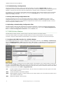
1.3 DXM Modbus Overview
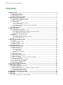
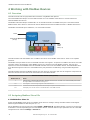
The DXM Controller uses internal 32-bit registers to store information. The internal local registers serve as the main global
pool of registers used as the common data exchange mechanism. External Modbus device registers can be read into the
local registers or written from the local data registers.
The DXM Controller, as a Modbus master device or
slave device, exchanges data using the local
registers. Modbus over Ethernet (Modbus/TCP) uses
the local registers as the accessible register data.
Using Action, Read/Write, and Threshold Rules
allows you to manipulate the local registers to
create solutions for applications. The ScriptBasic
programming capabilities extends the use of local
registers with its own variables to create a flexible
programming solution for more complex
applications.
The local registers are divided into two different
types: 32-bit integer and 32-bit floating point.
When using local registers internally, the user can
store 32-bit numbers. Using local registers with
external Modbus devices follows the Modbus
standard of a 16-bit holding register.
Accessing the I/O Base and the LCD display follows
the same communication as an external Modbus
slave device. Each device has a slave ID number to
uniquely identify itself. The I/O base is Modbus
slave ID 200 and the LCD is Modbus slave ID 201.
DXM Controller Modbus Overview
Internal Processor (Modbus SID 199)
I/O Base (Modbus SID 200)
Display (Modbus SID 201)
ISM Radio (Modbus SID X)
Ethernet
RS232
RS485 (master)
RS485 (slave)
USB
Action Rules
Script Basic
Rd/Wr Rules
Data
Traffic
Control
Local
Registers
32-bit
Local
Registers
32-bit Float
LED
Display
Registers
Gateway/
MultiHop
Registers
I/O Base
Data
Registers
I/O Base
Config
Registers
DXM100 Controller Instruction Manual
4 www.bannerengineering.com - Tel: 763.544.3164

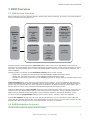
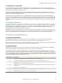
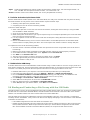
1.4 DXM Configuration Tool Overview
The main storage elements for the DXM Controller are its Local
Registers, which can store up to 4-byte values that result from
register mapping, action rules, or ScriptBasic commands.
The Register Mapping function has two main components: a read
rule and a write rule. These rules allow the user to program the ability
to read or write information from Modbus slaves to/from the local
registers.
The Action Rules allow for logic functions and manipulation of local
register data. Action rules are processed autonomously from other
local register functions. There are three types of action rules:
thresholds, register copy, and math/logic.
Use the Scheduler
to program when values are sent to a local
register during a specific time, day, or week. Events can be
programmed by days of the week with the ability to create holidays
for exception conditions.
Use the Register View Utility to read or write local registers within
the DXM Controller or Modbus Slave devices connected to the DXM
Controller. This allows the user to debug connections to external
devices by viewing live local register data within the controller.
The System Settings define parameters for the DXM Controller,
including email notifications, Cloud settings, time of day settings, local
logging settings, SMS messaging, ScriptBasic programming control,
and Ethernet network settings.
USB
Ethernet
DXM Configuration Software
Local Registers
Register
View Utility
Scheduler
Action Rules
Register Mapping
XML Config File
Script Basic
System
Settings
The DXM Configuration Tool configures the DXM Controller by creating an XML file that is transferred to the DXM Controller
using a USB or Ethernet connection. The
DXM Controller can also receive the XML configuration file from a Web server
using a cellular or Ethernet connection.
This configuration file governs all aspects of the DXM Controller operation. The wireless network devices are a separate
configurable system. Use the DX80 User Configuration Tool (UCT) to configure the internal DX80 wireless Gateway and the
attached wireless Nodes. Use the MultiHop Configuration Tool (MCT) if the internal radio is a MultiHop device.
All tools can be connected to the DXM Controller using a USB cable or an Ethernet connection. Each tool can be run
individually or launched through the DXM Configuration Tool.
DXM100 Controller Instruction Manual
www.bannerengineering.com - Tel: 763.544.3164 5

2 DXM Hardware Configuration
2.1 DXM Hardware Configuration Overview
The DXM100 Controller can have multiple configurations. The DXM100 Controller will have a model number label on the
housing. Use the model number and model table above to identify which boards are included in the controller.
When opening the
DXM100 Controller, follow proper ESD grounding procedures. Refer to the ESD warning in the appendix.
Cellular Radio Board
SAM4 Processor Board
MultiHop or Gateway
Radio Board
DXM100 I/O Board
Cellular Antenna
Connection
ISM Radio
Antenna
Connection
Housing Catch
The DXM100 Controller I/O base board provides connections for all inputs, outputs and power. The base board also
contains a 12 V solar controller that accepts connections to a solar panel and SLA battery. The battery connection can also
be used with line power to provide a battery backup in case of line power outages.
The ISM radio, either a MultiHop or DX80 Gateway, fits on the base board in the parallel sockets. Install the ISM radio so
the U.FL antenna connection is to the side with the SMA antenna connectors. Connect the U.FL cable from the ISM radio
U.FL to the right side U.FL connector. The ISM radio boards are available with either a 900 MHz radio or a 2.4 GHz radio.
The SAM4 processor board plugs into the base board using the two 20 pin socket connectors. The board sits above the ISM
radio socket and held by the base board standoffs. Position the processor board so the USB and RJ45 Ethernet connection
is to the front, away from the SMA antenna connections.
The top plugin PCB is the optional cellular radio. This plugs into the SAM4 processor board with the U.FL antenna
connection to the left. Attach the antenna cable from the cellular module to the left U.FL connection on the base board.
The top housing contains the LCD display board. The display board is connected to the base board using a ribbon cable
with a 20 pin connector.
In some DXM models, the cellular radio module may be replaced with an ISM radio. The top ISM radio antenna connection
will be to the left SMA connector.
DXM100 Controller Instruction Manual
6 www.bannerengineering.com - Tel: 763.544.3164

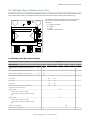
2.2 ISM Radio Board (Modbus Slave ID 1)
The ISM radio board may be a MultiHop radio (DX80DR*M-HE5) or a Performance Gateway radio (DX80G*M2S-PE5). Refer
to the model number label on the
DXM100 Controller and the model number table to identify the ISM radio type.
5
1
ON
ON
A
D1
B
C
D2
234
678
The ISM radio should be plugged into the I/O base board
with the U.FL antenna connector closest to the SMA
connectors.
A - Antenna connector
B - Button
C - LED
D1 and D2 - DIP switches
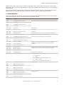
2.2 MultiHop (HE5) DIP Switch Settings
Switches
Device Settings 1 2 3 4 5 6 7 8
Serial line baud rate 19200 OR User defined receiver
slots
OFF* OFF*
Serial line baud rate 38400 OR 32 receiver slots OFF ON
Serial line baud rate 9600 OR 128 receiver slots ON OFF
Serial line baud rate Custom OR 4 receiver slots ON ON
Parity: None OFF* OFF*
Parity: Even OFF ON
Parity: Odd ON OFF
Disable serial (low power mode) and enable the
receiver slots select for switches 1-2
ON ON
Transmit power
900 MHz radios: 1.00 Watt (30 dBm)
2.4 GHz radios: 0.065 Watts (18 dBm) and 60 ms
frame
OFF*
Transmit power
900 MHz radios: 0.25 Watts (24 dBm)
2.4 GHz radios: 0.065 Watts (18 dBm) and 40 ms
frame
ON
Application mode: Modbus OFF*
Application mode: Transparent ON
DXM100 Controller Instruction Manual
www.bannerengineering.com - Tel: 763.544.3164 7

Switches
Device Settings 1 2 3 4 5 6 7 8
MultiHop radio setting: Repeater OFF* OFF*
MultiHop radio setting: Master OFF ON
MultiHop radio setting: Slave ON OFF
MultiHop radio setting: Reserved ON ON
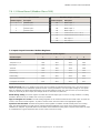
2.2 Performance Gateway (PE5) DIP Switch Settings
Switches
Device Settings 1 2
Transmit Power Level: 1 Watt (30 dBm) OFF (default)
Transmit Power Level: 250 mW (24 dBm), DX80 Compatibility Mode ON
2.2 Button Operation
Typically you use the DXM LCD to put the device into binding mode, but you may also use the button on the ISM radio
boards to enter binding mode. However, most DXM models will not provide access to this button.
2.2 LED Operation
The LED located on the ISM radio module indicates power and communications traffic.
•
Solid green DX80 ISM radio LED: Indicates power.
• Flashing green MultiHop ISM radio LED indicates operation.
• Red and green combined: Communications traffic and binding.
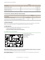
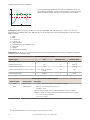
2.3 SAM4 Processor Board
1
P2
A
A
B
D
E
C
LED 1
LED 2
LED 3
LED 4
A - Cellular radio connection
B - Force cloud push/Clear password
C - Boot load jumpers
D - DIP switches
E - Micro SD card
Cellular Radio Connection. Install the cellular modem onto the SAM4 board with the cellular modem's U.FL connector on
the left. The antenna cable will go between the cellular U.FL connector and the left I/O board U.FL connector. Only install/
remove a cellular modem when the power to the device is disconnected.
Force Cloud Push button. Press and hold this button for two seconds to send an immediate push message from the
device (if properly configured).
DXM100 Controller Instruction Manual
8 www.bannerengineering.com - Tel: 763.544.3164

Clear Password. By default, the
DXM Controller does not require a password to load a configuration file. If a password is
defined, the DXM Controller requires that you enter the password before uploading a configuration file. To change the
password, you must already know the current password. If you do not know the current password, clear the password
from the DXM Controller.
CAUTION: Clearing the password erases the current configuration and any program files, log files, or
history files currently on the
DXM Controller.
Follow these steps to clear the password requirement from your DXM Controller.
1.
Turn off the power.
2. Set DIP switch 4 to the ON position.
3. Press and hold button 'B'.
4. Apply power to the device.
5. After leaving the device powered on for a few seconds, turn off the power again.
6. Set DIP switch 4 to the OFF position.
7. Reload the configuration file before resuming normal operation.
The password is cleared from the system.
2.3 DIP Switch Configuration
Cycle power to the device after making any changes to the DIP switch settings.
Settings
DIP Switches
1 2 3 4
Disable Ethernet Port
OFF *
ON
Disable LCD Display
OFF *
ON
Not used OFF *
Bypass XML
OFF *
ON
Bypass XML
Turn to ON to have the XML file ignored at boot time. This is useful for ignoring a corrupt or questionable XML
configuration file. After the device is running, a new XML file can be loaded using the DXM configuration tool. The
factory default position is OFF.
Disable Ethernet Port
Set to ON to power down the Ethernet interface. The factory default position is OFF.
Disable LCD Display
Set to ON to disable the LCD. This DIP switched should be ON when the LCD display board is not connected. The
factory default position is OFF.
2.3 Button Operation
The SAM4 processor button has two functions:
•
Clearing the access password as explained above.
• Pressing the button for 5 seconds forces a Push to the webserver. This assumes a proper configuration for the
webserver.
2.3 LED Operation
By default, the four LEDs indicate the following conditions:
• LED 1 - Heartbeat, indicates the processor is running.
• LED 2 - Indicates the cellular modem power cutoff is active. If the incoming power is less than 11.2 V, the cellular
modem is powered down.
• LED 3 - XML configuration file was rejected.
• LED 4 - ScriptBasic program failed to load.
DXM100 Controller Instruction Manual
www.bannerengineering.com - Tel: 763.544.3164 9

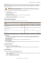
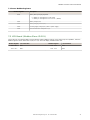
2.4 I/O Base Board
ON
ON
1
1
1
1
1
1
1
1
LED2
C95
TB1
C6
R121
FET9
R82
TB4
P2
P4
SW1
C4
P5
P16
SW2
P10
IC18
TB3
P7
TB2
TB9
Y1
SW3
P6
L2
C19
C18
C20
TB5
D3
R118
R122
TVS1
L1
R120
DZ2
R77
C10
D5
D4
P9
P8
P1
LED1
P3
A
B
C
D
E
F
G
H
J
K
L
1 18
1932
mA
V
A OUT 2
A OUT 1
For the complete I/O base board definitions, see I/O Base Board Connections on page
13.
A Base board LED E
Jumpers - Configures Analog Out
1 and 2 for mA or V
J Modbus Slave ID DIP Switches
B A1. Cellular antenna F Radio Binding Button K Modbus Slave ID DIP Switches
C Radio LED G Programming header L SAM4 Processor Board Connection
D A2. ISM Antenna H ISM Radio Board Connection
2.4.1 DIP Switches for the I/O Board
The
DXM100 Controller I/O board DIP switches are set from the factory to Modbus Slave ID 200 and should not need to be
changed. For more advanced information about the DIP switches, refer to Setting the Modbus Slave ID on the I/O Base
Board on page 11.
2.4.2 I/O Board Jumpers
Hardware jumpers on the DXM I/O board allow the user to select alternative pin operations. Turn the power off to the
device before changing jumper positions.
Jumper Function Positions
E Analog output characteristics
for AO2 (pin 19) and AO1 (pin
20)
Defines current (0–20 mA) or voltage (0–10 V) for analog output 1 and 2.
By default, current (0–20 mA) is selected using jumpers 1 and 2 and registers 4008 and
4028 contain a value of 2.
To select voltage (0–10 V) for output Aout1, set jumper 1 in the voltage position (V) and
set Modbus register 4008 on the I/O board (SID 200) to 3.
To select voltage (0–10 V) for output Aout2, set jumper 2 in the voltage position (V) and
set Modbus register 4028 on the I/O board (SID 200) to 3.
DXM100 Controller Instruction Manual
10 www.bannerengineering.com - Tel: 763.544.3164

Jumper Function Positions
M Courtesy power output P3 The jumper selects 5 V when in the "a" position and incoming power (pin 2) in the "b"
position.
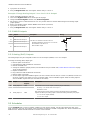
2.4.3 Setting the Modbus Slave ID on the I/O Base Board
Only DXM Slave models require that the Modbus Slave ID to be adjusted on the I/O base board. The
DXM100 Controller
models use DIP switches J and K to set the Modbus Slave ID. This device can use a Modbus register 6804 in the I/O board
to access the full range of Modbus Slave IDs.
On the DXM100 Controller models, use the DIP switches at location K to define the lower digit of the Modbus Slave ID.
2.4.3 DXM100 Controller Models
DIP Switch location J defines the course group of Modbus Slave IDs. DIP Switch 4 must be set to ON for DXM100-S1 and
DXM100-S1R2 models.
Settings
Location J DIP Switches
1 2 3 4
Modbus Slave ID set to 11 through 19 OFF OFF
Modbus Slave ID set to 20 through 29 ON OFF
Modbus Slave ID set to 30 through 39 OFF ON
Modbus Slave ID set to 40 through 49 ON ON
Not Used -
Modbus Slave Configuration (S1 model only)
1
ON
I2C Processor Communication OFF
DIP Switches J DIP Switch K, Switches 1, 2, 3, 4 (0 is OFF, 1 is ON)
1 2 0,0,0,0 1,0,0,0 0,1,0,0 1,1,0,0 0,0,1,0 1,0,1,0 0,1,1,0 1,1,1,0 0,0,0,1 1,0,0,1
OFF OFF x
2
11 12 13 14 15 16 17 18 19
ON OFF 20 21 22 23 24 25 26 27 28 29
OFF ON 30 31 32 33 34 35 36 37 38 39
ON ON 40 41 42 43 44 45 46 47 48 49
DXM100 Controller Example
To set the
DXM100 Controller to a Modbus Slave ID of 34, set the following:
Location J DIP switches set to 1=OFF, 2=ON
Location K DIP switches set to 1=OFF, 2=OFF, 3=ON, 4=OFF
The location J DIP switches set the upper Modbus Slave ID digit to 3 while the location K DIP switches set the lower digit to
4.
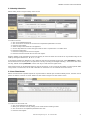
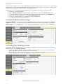
2.4.3 Setting the DXM I/O Board Modbus Slave ID using Modbus Registers
Write to the I/O board's Modbus register 6804 to set the Modbus Slave ID to any valid Modbus Slave ID (1 through 245).
• For the DXM100 Controller model, all switches on DIP switch K should be in the OFF position to use the Modbus
register slave ID.
1
Must be in the ON position for the -S1 model)
2
Uses value in Modbus register 6804.
DXM100 Controller Instruction Manual
www.bannerengineering.com - Tel: 763.544.3164 11

2.5 Cellular Modem Board
A
The optional cellular modem is installed on the SAM4 processor
board on the two 12-pin sockets. The U.FL connector should be to
the left, with the antenna cable going to the left antenna U.FL
connector.
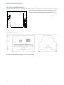
2.6 DXM100 Dimensions
All measurements are listed in millimeters, unless noted otherwise.
DXM100 Controller Instruction Manual
12 www.bannerengineering.com - Tel: 763.544.3164

3 DXM Connections
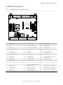
3.1 I/O Base Board Connections
ON
ON
1
1
1
1
1
1
1
1
LED2
C95
TB1
C6
R121
FET9
R82
TB4
P2
P4
SW1
C4
P5
P16
SW2
P10
IC18
TB3
P7
TB2
TB9
Y1
SW3
P6
L2
C19
C18
C20
TB5
D3
R118
R122
TVS1
L1
R120
DZ2
R77
C10
D5
D4
P9
P8
P1
LED1
P3
A
B
C
D
E
F
G
H
J
K
L
1 18
1932
mA
V
A OUT 2
A OUT 1
1 No connection 12 CT. RS-232 CTS 23 N3. NMOS OUT 3
2
PW. 12 to 30 V dc or solar power in
(+)
13 S-. Secondary RS-485 – 24 N2. NMOS OUT 2
3 GD. Ground 14 S+. Secondary RS-485 + 25 N1. NMOS OUT 1
4 B+. Battery in (< 15 V dc) 15 CL. CANL 26 GD. Ground
5 GD. Ground 16 CH. CANH 27 U4. Universal Input 4
6 M-. Primary RS-485 – 17 GD. GND 28 U3. Universal Input 3
7 M+. Primary RS-485 + 18 P3. Courtesy Power 5 V 29 GD. Ground
8 GD. Ground 19 A2. Analog OUT 2 30 P1. Switch Power (5 V or 16 V)
9 TX. RS-232 Tx 20 A1. Analog OUT 1 31 U2. Universal Input 2
10 RX. RS-232 Rx 21 P2. Switch Power (5 V or 16 V) 32 U1. Universal Input 1
11 RT. RS-232 RTS 22 N4. NMOS OUT 4
A Base board LED E
Jumpers - Configures Analog Out
1 and 2 for mA or V
J Modbus Slave ID DIP Switches
B A1. Cellular antenna F Radio Binding Button K Modbus Slave ID DIP Switches
C Radio LED G Programming header L SAM4 Processor Board Connection
D A2. ISM Antenna H ISM Radio Board Connection
DXM100 Controller Instruction Manual
www.bannerengineering.com - Tel: 763.544.3164 13

3.2 Applying Power to the DXM100 Controller
Apply power to the DXM100 Controller using either 12 to 30 V dc or a 12 V dc solar panel and 12 V sealed lead acid
battery
operating together.
The DXM100 has three power input and three power output options:
• For inputs
◦ 12 to 30 V dc
◦ 12 to 30 V dc solar panel
◦ 12 V dc sealed lead acid battery with automatic charging
• For outputs
◦ One 5 V dc fixed
◦ Two 5 V dc or 16 V dc switched
The DXM Controller continuously monitors the health of the power inputs. If a power input fault is detected, the DXM
Controller automatically switches over to battery with continuous uninterrupted operation.
If the incoming voltage drops below 11.2 V, the cellular modem does not turn on and will not turn on until the voltage is
above 11.8 V. A text file (CmVMon.txt) on the internal micro SD card saves the periodic sampling of the incoming voltage.
If cellular operation stops because of voltage, it is logged in this file.
The DXM Controller automatically charges the sealed acid battery. The charging algorithm is designed to work with a
sealed lead acid (SLA) battery only.
• When using 12 to 30 V dc , connect the 12 to 30 V dc + to pin 2 and connect the ground to pin 3.
• When using main dc power with a back up battery (default configuration), connect the incoming main power pin 2
(+) and to pin 3 (-). Connect the 12 V sealed lead acid battery to pin 4 (+) and pin 5 (-). The incoming main power
must be 15 to 30 V dc to charge the battery.
• When using a solar panel, connect the solar panel output to pin 2 and connect the ground to pin 3. Connect the 12
V dc SLA battery to pin 4 (+) and pin 5 (-). To change the charging algorithm, refer to Supplying Power from Solar
(B1 and S1).
Pin Description
Pin 1 No connection
Pin 2 12 to 30 V dc input (+) or solar panel connection (+)
Pins 3, 5, 8, 17, 26, 29 Main logic ground for the DXM100 Controller
Pin 4 Solar or backup battery positive input. Battery voltage must be less than 15 V dc. Use only a sealed lead acid (SLA)
battery.
3.2 Using Courtesy Power or Switch Power
Pin 18 of the
DXM100 Controller is a constant power source that supplies 5 volts up to 500 mA.
Pins 21 (switch power 2) and 30 (switch power 1) are switched power outputs. Configure the switched power outputs using
Modbus registers. The output voltage can be either 5 volts or 16 volts and is controlled using a Modbus register on the I/O
board (Modbus slave ID 200).
Switch Power Enable Register Voltage Register
1 (pin 30)
2201
Write a 0 to turn OFF
Write a 1 to turn ON (default)
3601
Write a 0 to select 5 V (default)
Write a 1 to select 16 V
2 (pin 21)
2251
Write a 0 to turn OFF
Write a 1 to turn ON (default)
3621
Write a 0 to select 5 V (default)
Write a 1 to select 16 V
3.2.1 Supplying Power from 12 to 30 V dc and a Battery Backup
The factory default setting for the battery charging algorithm assumes you are using
12 to 30 V dc to recharge the battery.
DXM100 Controller Instruction Manual
14 www.bannerengineering.com - Tel: 763.544.3164

Modbus Slave ID Modbus Register Description
200 * 6071 Battery backup charging algorithm.
0 = Battery is recharged from a solar panel
1 = Battery is recharged from
12 to 30 V dc . (default)
* The Modbus Slave ID for the base board is set at the factory. This may be changed using the base board DIP switch
settings.
3.2.2 Supplying Power from a Solar Panel
To power the
DXM100 Controller from a 12 V dc solar panel, connect the solar panel to power pins 2(+) and 3(-). Connect
a 12 V dc sealed lead acid (SLA) rechargeable battery to pins 4(+) and 5(-).
The factory default setting for the battery charging algorithm assumes you are using 12 to 30 V dc power to recharge the
battery. If the incoming power is from a solar panel, you must change the charging algorithm.
To change the charging algorithm from the menu system:
1. From the LCD menu, select Update > Power.
2. Use the up/down arrows to select "SOLAR" power.
To change the charging algorithm by writing to Modbus register 6071 on the I/O base board (Slave ID 200):
1. Write a 0 to select the solar power charging algorithm.
Modbus Slave ID Modbus Register Description
200 * 6071 Battery backup charging algorithm.
0 = Battery is recharged from a solar panel
1 = Battery is recharged from
12 to 30 V dc . (default)
The following power operating characteristics are stored in Modbus registers.
Battery voltage If no battery is present, the value in this register is less than 5 V. If the value in this register is
greater than the incoming voltage register, the battery is powering the system.
Battery charging
current
The charging algorithm charges the battery when the incoming voltage register value is greater
than the battery voltage register value. This registers shows the charging current in milliamps.
Incoming supply
voltage
The incoming power can be from a solar panel or from a power supply. The battery is charging
when the incoming voltage register value is greater than the battery voltage register value. The
battery is powering the system when the incoming voltage register value is less than the battery
voltage register value.
On-board
thermistor
temperature
This register stores the on-board thermistor reading in tenths of degrees C, this is not a calibrated
input: divide by 10 to calculate the temperature in degrees C. For calibrated temperature inputs,
define one of the universal inputs as a temperature input.
Modbus Slave ID Modbus Register Description
200 * 6081 Battery voltage (mV)
6082 Battery charging current (mA)
6083 Incoming supply voltage (mV) (solar or power supply)
6084 On-board thermistor temperature (⁰C)
* The Slave ID for the base board is set at the factory. This may be changed using the base board DIP switch settings.
3.3 Connecting the Communication Pins
The base board communications connections to the device are RS-485 (primary), RS-485 (secondary) or RS-232.
RS-485. The primary RS-485 bus is a common bus shared with the ISM radio board (Modbus Slave ID 1) or optional
cellular board. The
DXM100 Controller is defined as the Modbus Master on this bus. Other internal Modbus slaves include
the local processor registers (Modbus Slave ID 199), the base I/O controller (Modbus Slave ID 200), and the display board
(Modbus Slave ID 201). When assigning Modbus Slave IDs to externally connected devices, only use IDs 2 through 198.
DXM100 Controller Instruction Manual
www.bannerengineering.com - Tel: 763.544.3164 15

RS-232. The RS-232 bus is not currently defined.
Pin Parameter Description
Pin 6 Primary RS-485 –
Running Modbus protocol at 19.2k baud, use this bus to connect to other Modbus
Slave devices. The
DXM100 Controller is a Modbus Master device on this RS-485 port.
Pin 7 Primary RS-485 +
Pin 9 RS-232 Tx
Serial RS-232 connection. This bus must use a ground connection between devices to
operate correctly.
Pin 10 RS-232 Rx
Pin 13 Secondary RS-485 –
The DXM100 Controller is a Modbus slave on this bus (see I/O Base Board Connections
on page 13).
Pin 14 Secondary RS-485 +
Pin 15 CANL –
Pin 16 CANH +
3.3 Modbus RTU Master/Modbus RTU Slave
The
DXM100 Controller can be a Modbus RTU master device to other slave devices and can be a Modbus slave device to
another Modbus RTU master. The DXM100 Controller uses the primary RS-485 port (pins 6 and 7) as a Modbus RTU
master to control external slave devices. The secondary port (pins 11 and 12) is the Modbus RTU slave connection.
• As a Modbus RTU master device, the DXM100 Controller controls external slaves connected to the primary RS-485
port, the local ISM radio, local I/O base board, and the local display board.
• As a Modbus RTU slave device, the DXM100 Controller local registers can be read from or written to by another
Modbus RTU master device.
Use the DXM Configuration Tool to define operational settings for both the Modbus RTU master port and the Modbus RTU
slave port.
3.4 Ethernet
Before applying power to the DXM100 Controller, verify the Ethernet cable is connected. If the Ethernet cable is not
connected when the device powers up, the DXM100 Controller will not recognize the connection.
The Ethernet connection supports the DXM Configuration Tool, Modbus/TCP, and EtherNet/IP. ScriptBasic also has access
to Ethernet for custom programming. Use the DXM Configuration Tool to configure the characteristics of the Ethernet
connection, fixed IP addresses, DHCP, etc. The LCD menu allows the user to change the IP Address.
3.5 Modbus Master Port and Slave Port
There are two RS-485 ports on the DXM Controller, a Modbus master RS-485 port and a Modbus slave RS-485 port.
The Modbus master RS-485 is controlled by the
DXM Controller, which acts as the Modbus master. All wired devices
connected to the master RS-485 port must be slave devices.
The Modbus slave RS-485 port is controlled by another Modbus master device, not the DXM Controller. The slave port is
used by other devices that want to access the DXM Controller as a Modbus slave device. All local registers are available to
be read or written from this slave port. Set the Modbus Slave ID for the secondary RS-485 port using the LCD display
menu: System > DXM Slave ID.
3.5.1 Modbus Master and Slave Port Settings
The basic communications parameters for the RS-485 ports are set in the DXM Configuration Tool and are saved in the
XML configuration file. All basic settings are available under Settings > General screen of the DXM Configuration Tool.
Master port parameters include:
• Baud rate and parity
• Set the Communications Timeout parameter to cover the expected time for messages to be sent throughout the
wireless network. For the DXM Controller, the Communications Timeout parameter is the maximum amount of
time the DXM Controller should wait after a request is sent until the response message is received from the Modbus
slave device.
• Maximum Polling Rate sets the minimum wait time from the end of a Modbus transaction to the beginning of the
next Modbus transaction.
DXM100 Controller Instruction Manual
16 www.bannerengineering.com - Tel: 763.544.3164

The Modbus Slave port settings include:
• Baud rate and parity (also set on this screen)
•
Set the Modbus Slave port ID using the DXM Controller LCD
• Set the Wireless Modbus Backbone parameter when there is an ISM radio plugged into the SAM4 processor
board and the Modbus slave port is using the MultiHop radio as the slave port instead of the terminal block
connection.
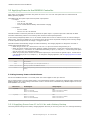
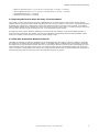
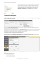
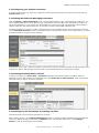
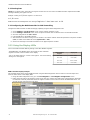
3.5.2 Modbus Slave Port ID
Set the DXM Modbus slave port using the LCD menu system. On the LCD,
use the down arrow to highlight System. Enter the System menu by
clicking Enter.
Banner Eng .
08:25:45
→ Registers
→ Push S → 08:25:15
→
ISM Radio
→ System
↑
↓
ENTER
BACK
→ System Info
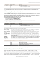
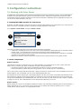
To change the DXM Slave ID, highlight DXM Slave ID, then click Enter.
System
08:25:45
→ DXM Slave ID: -1
→ Provision Cell
→ Power: [dc / solar]
→ Restart!
ENTER
BACK
↑
↓
Use the up and down arrow buttons to change the DXM Slave ID.
Press Enter to accept the ID change.
After you change the DXM Slave ID, use the DXM Configuration Tool to cycle power to the device. After cycling power to
the device, the updated DXM Slave ID is listed under the System
menu.
3.6 USB
The USB port is used with the DXM Configuration Tool to program the DXM100 Controller. The USB port is also used as the
console output for the processor and ScriptBasic.
DXM100 Controller Instruction Manual
www.bannerengineering.com - Tel: 763.544.3164 17

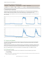
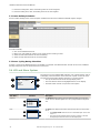
4 Working with Modbus Devices
4.1 Overview
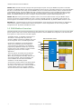
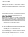
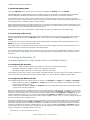
The DXM Controller has two physical RS-485 connections using Modbus RTU protocol.
The master Modbus RS-485 port is for the
DXM Controller to act as a Modbus master device to control internal and
external Modbus slave devices.
The Modbus master RS-485 port is labeled M+, M- on the DXM Controller. The Modbus slave port is used when another
Modbus master device wants to communicate with the DXM Controller when the DXM Controller is a Modbus slave device.
The Modbus slave RS-485 port is labeled S=, S1 on the DXM Controller.
Ethernet
Modbus RS-485
(slave
port)
Processor Modbus
Control/Data
External
Modbus
Slaves (2-10)
Modbus RS-485
(master port)
Modbus
SID
199
Modbus
SID
1
Modbus
SID
201
Modbus
SID
200
Local
Registers
GW/MH
Radio
Display I/O Base
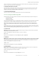
The DXM Controller has dual Modbus roles: a Modbus slave device and a Modbus master device. These run as separate
processes.
The Modbus slave port allows access into the
DXM Controller local registers. To operate as a Modbus slave device, the DXM
Controller needs to be assigned a unique Modbus slave ID as it pertains to the host Modbus network. This slave ID is
separate from the internal Modbus slave IDs the DXM Controller uses for its own Modbus network. The DXM Modbus slave
ID is defined through the LCD menu. Other Modbus slave port parameters are defined by using the DXM Configuration
Tool.
The DXM Controller operates the Modbus master port. Each device on the master port must be assigned a unique slave ID.
There are slave IDs that are reserved for internal devices in the DXM Controller.
DXM Internal Modbus Slave IDs (factory default)
Modbus Slave ID Device
1 Gateway (PE5) or MultiHop (HE5) ISM Radio—MultiHop wireless devices connected to the internal MultiHop radio should
be assigned Modbus Slave addresses starting at 11.
199 Local Registers—Internal storage registers of the DXM Controller
200 I/O Base Board—All data and parameters for each input or output of the DXM Controller.
201 LCD Display—The user has access to the LED indicators on the DXM Controller.
4.2 Assigning Modbus Slave IDs
4.2 DXM Modbus Slave ID
Assign the DXM Modbus Slave ID only if a Modbus master device is reading or writing the
DXM Controller Local Register
data through the Modbus RS-485 slave port (S+, S-).
Set the DXM Slave ID from the LCD menu under System > DXM Slave ID. The DXM Controller can have any unique slave
ID between 1 and 246, depending upon the host Modbus network. Other RS-485 slave port parameters are set in the DXM
Configuration Tool under the Settings > General tab.
DXM100 Controller Instruction Manual
18 www.bannerengineering.com - Tel: 763.544.3164

4.2 DXM Master Configuration
The
DXM Controller operates as a Modbus master device, use the DXM Configuration Tool to configure read or write
operations of the DXM Modbus network. The DXM Controller communicates with all internal and external peripheral devices
using the external Modbus bus RS-485 (M+, M-)
There are four internal Modbus slave devices that are configured from the factory with slave IDs. Assign slave IDs of 2
through 10 to Modbus slave devices that are physically wired to the DXM Controller. Assign slave IDs or 11 through 60 to
wireless slaves within the MultiHop network.
Do not assign a slave ID of greater than 10 to Modbus slave devices that are physically wired using the RS-485 port if
there is an internal MultiHop ISM radio in the DXM Controller. The MultiHop ISM radio attempts to send any Modbus data
intended for slaves 11–60 across the radio network, which conflicts with wired slave devices if the slave IDs overlap. The
MultiHop master radio can be changed from the factory default of 11–60 Modbus slave IDs if more hardwired slaves are
required.
4.3 Modbus Operation
All Modbus transactions are managed by a central Modbus engine. If there are Modbus messages intended for a Modbus
slave that doesn't exist, the Modbus engine waits for a response until the timeout period is expired. This slows down the
Modbus polling loop for read and write operations. For this reason, verify all Modbus read and write operations are
intended for Modbus slave devices that are in the network.
If a Modbus slave is not in the network, either a wired or wireless device, the operation of the LCD menu system can be
compromised. Operations like Binding, Site Survey, or accessing the ISM menu may be slower. This is because all internal
devices of the
DXM Controller are also Modbus slaves, ISM radio, I/O base board, LCD, and internal Local registers.
4.4 Wireless and Wired Devices
4.4 Wireless DX80 Gateway
The DX80 Gateway architecture is a star architecture in which all Nodes in the system send their data back to the
Gateway. The host can access the entire network data from the Gateway, which is Modbus slave ID 1.
Because the
DXM Controller will not be sending any Modbus messages across the wireless link, the timeout parameter can
be set low (less than 1 second) and it is treated like a directly connected device.
4.4 MultiHop Master
The MultiHop master radio forms a wireless tree network using repeaters and slave devices. Each device in a MultiHop
network must be assigned a unique Modbus Slave ID and is accessed as a separate device.
For the DXM Controller to talk with a MultiHop device in the wireless network, the master MultiHop device interrogates
every message on the RS-485 bus. If they are within the wireless devices range (slave IDs 11 though 60), the message is
sent across the wireless network. To change this range, the user must adjust the offset and range setting in the MultiHop
master radio (Modbus Slave ID 1). Modbus register 6502 holds the Modbus offset, default 11. Modbus register 6503 holds
the number of Modbus slaves allowed (maximum of 100).
Modbus Slave ID Description
1 Allocated for the internal ISM radio device, either a DX80 Gateway or MultiHop Master
2–10 Slave addresses available for direct connected Modbus slave devices to the master RS485 port (M+ , M-)
11–60 Allocated for wireless MultiHop radio network devices. If there is not an internal MultiHop in the DXM Controller, these slave
addresses are available to use for directly connected devices.
61–198 Available to user for direct connected Modbus slave devices or the expansion of the wireless network slave IDs to go past 50
wireless devices.
199 Allocated for internal Local Register
200 Allocated for the I/O base board, will be different for special DXM slave only models.
201 Allocated for the LCD display board, the user can read/write LEDs.
DXM100 Controller Instruction Manual
www.bannerengineering.com - Tel: 763.544.3164 19

4.5 Modbus Timeouts
A Modbus timeout is the amount of time a Modbus slave is given to return an acknowledgement of a message sent by the
Modbus master. If the Modbus master waits for the timeout period and no response is seen, the Modbus master considers
it a lost message and continues on to the next operation.
The timeout parameter is simple to set for Modbus devices directly connected to the DXM controller, if there are no
MultiHop wireless devices. If a MultiHop network a part of the
DXM Controller, special considerations need to be made to
set the timeout parameter.
Wireless communications are inherently lossy networks, and controllers operating these networks must be configured to
allow for enough time for hardware transmission retries. Set the Communications Timeout parameter to cover the
expected time for messages to be sent throughout the wireless network. For the DXM Controller, the Communications
Timeout parameter is the maximum amount of time the DXM Controller should wait after a request is sent until the
response message is received from the Modbus slave device. Use the DXM Configuration Tool to set the timeout parameter
on the Settings > General screen.
The default setting for the timeout parameter is 5 seconds.
4.5 MultiHop Networks vs DX80 Star Networks
The MultiHop wireless architecture is much different from the DX80 star architecture. Although both are wireless networks,
the DX80 star Gateway collects all the data from the Nodes, which allows the host system to directly read the data from
the Gateway without sending messages across the wireless network. This allows for DX80 Gateway to be treated like any
other wired Modbus device.
In a MultiHop network, the data resides at each device, forcing the controller to send messages across the wireless
network to access the data. For this reason, carefully consider the value of the wireless timeout parameter.
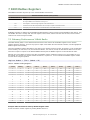
4.5 Battery-Powered MultiHop Radios
Battery-powered MultiHop radios are configured to run efficiently to maximize battery life. In optimizing battery life, the
allowed communications window for receive messages is slow (once per 1.3 seconds) and sending message rates are
standard (once per 0.04 seconds). A MultiHop device is set from the factory with the retry parameter set to 8. This means
that under worst-case conditions, a message is sent from the DXM Controller to an end device a total of nine times (one
initial message and eight retry messages. The end device sends the acknowledgement message back to the DXM
Controller a maximum of nine times (one initial message and eight retries). A single Modbus transaction may send up to
two messages + 16 retry messages before the transaction is complete. In addition, the radios randomly wait 0–1 time
period before retransmitting a retry message. So to allow for the random wait time, add one extra time period for each in-
between time of retries.
For a Master radio to a slave radio (no repeaters):
• Master to Slave Send time = (9 × 1.3 sec) + (8 retry wait × 1.3 sec) = 22 seconds
• Slave to Master Send time = (9 × 0.04 sec) + (8 retry wait × 0.04 sec) = 1 second
• Total Send/Receive time = 23 seconds
• Minimum Timeout period = 23 seconds
This calculates the maximum timeout value for a wireless transaction. If the link quality of the network is poor, the
maximum transfer times may happen. Set the timeout parameter to accommodate the maximum number of retries that
may happen in your application.
When MultiHop repeaters are added into the wireless network, each additional level of hierarchical network increases the
required timeout period. Since MultiHop repeaters are running at the highest communications rate, the overall affect is not
as great.
• Master to Repeater Send time = (9 × 0.04 sec) + (8 retry wait × 0.04 sec) = 1 second
• Repeater to Master Send time = (9 × 0.04 sec) + (8 retry wait × 0.04 sec) = 1 second
• Additional Timeout period for a repeater = 2 seconds
Using the timeout calculation above of 23 seconds, if a repeater is added to the network the timeout should be set to 25
seconds. For each additional MultiHop repeater device creating another level of network hierarchy, add an additional two
seconds to the timeout period.
4.5 Line-Powered MultiHop Devices
Line-powered (10–30 V dc) MultiHop devices operate at the maximum communication rate, resulting in a much lower
timeout parameter setting. For each repeater added to the network, increase the timeout parameter 2 seconds.
For a Master radio to a line powered slave radio (no repeaters):
DXM100 Controller Instruction Manual
20 www.bannerengineering.com - Tel: 763.544.3164
Page is loading ...
Page is loading ...
Page is loading ...
Page is loading ...
Page is loading ...
Page is loading ...
Page is loading ...
Page is loading ...
Page is loading ...
Page is loading ...
Page is loading ...
Page is loading ...
Page is loading ...
Page is loading ...
Page is loading ...
Page is loading ...
Page is loading ...
Page is loading ...
Page is loading ...
Page is loading ...
Page is loading ...
Page is loading ...
Page is loading ...
Page is loading ...
Page is loading ...
Page is loading ...
Page is loading ...
Page is loading ...
Page is loading ...
Page is loading ...
Page is loading ...
Page is loading ...
-
 1
1
-
 2
2
-
 3
3
-
 4
4
-
 5
5
-
 6
6
-
 7
7
-
 8
8
-
 9
9
-
 10
10
-
 11
11
-
 12
12
-
 13
13
-
 14
14
-
 15
15
-
 16
16
-
 17
17
-
 18
18
-
 19
19
-
 20
20
-
 21
21
-
 22
22
-
 23
23
-
 24
24
-
 25
25
-
 26
26
-
 27
27
-
 28
28
-
 29
29
-
 30
30
-
 31
31
-
 32
32
-
 33
33
-
 34
34
-
 35
35
-
 36
36
-
 37
37
-
 38
38
-
 39
39
-
 40
40
-
 41
41
-
 42
42
-
 43
43
-
 44
44
-
 45
45
-
 46
46
-
 47
47
-
 48
48
-
 49
49
-
 50
50
-
 51
51
-
 52
52


Ask a question and I''ll find the answer in the document
Finding information in a document is now easier with AI
Related papers
-
Banner DXM100-S Series User manual
-
-
-
-
-
-
-
Banner Sure Cross DX80N9X6S-P2 User manual
-
-
Other documents
-
ESP APKIT User manual
-
ClimateMaster DXM Owner's manual
-
GHOST CONTROLS DEP2 FAQ
-
LumenRadio W-Modbus User manual
-
 Davis Instruments #6810 Troubleshooting guide
-
POWERSHIELD Modbus Card for UPS Technical Manual
-
Schneider Electric 174CEV20030 Modbus Plus to Ethernet Bridge User manual
-
Xtreme MODBUS-IN User manual
-
-
Omega iMonnit-Enterprise Owner's manual
