Page is loading ...

DXM150-Sx Wireless Modbus Slave
Instruction Manual
Original Instructions
195455 Rev. C
23 July 2020
©
Banner Engineering Corp. All rights reserved
195455

Contents
1 System Overview .............................................................................................................................................................3
1.1 DXM150-S1 System Overview ........................................................................................................................................................ 3
1.2 DXM150-S2 System Overview ........................................................................................................................................................ 3
1.3 DXM Hardware Configuration Overview ..........................................................................................................................................3
2 ISM Radio ........................................................................................................................................................................ 5
2.1 ISM Radio Board (Slave ID 1) ......................................................................................................................................................... 5
2.2 DIP Switch Settings for the MultiHop HE5 Board Module .............................................................................................................. 5
2.2.1 Application Mode ..................................................................................................................................................................... 6
2.2.2 Baud Rate and Parity ............................................................................................................................................................... 6
2.2.3 Disable Serial ............................................................................................................................................................................6
2.2.4 Transmit Power Levels/Frame Size ..........................................................................................................................................6
2.3 Binding the ISM Radio of a Modbus Slave .....................................................................................................................................7
3 I/O Base Boards .............................................................................................................................................................. 8
3.1 Board Connections for the S1 Models ............................................................................................................................................ 8
3.2 Board Connections for the S2 Models ............................................................................................................................................ 9
3.3 DIP Switches for the I/O Board ......................................................................................................................................................10
3.4 I/O Board Jumpers ....................................................................................................................................................................... 10
3.5 Applying Power to the S1 Model ................................................................................................................................................... 10
3.6 Applying Power to the B2 or S2 Models ........................................................................................................................................11
3.7 Supplying Power from a Solar Panel ............................................................................................................................................. 11
3.8 Connecting a Battery ..................................................................................................................................................................... 11
3.9 Connecting the Communication Pins ........................................................................................................................................... 11
3.10 Inputs and Outputs ...................................................................................................................................................................... 12
3.10.1 Isolated Discrete Inputs .......................................................................................................................................................12
3.10.2 Universal Inputs ....................................................................................................................................................................12
3.10.3 PNP and NPN Outputs for the B1, B2, and S2 Models ....................................................................................................... 14
3.10.4 NMOS Outputs for the S1 Models ....................................................................................................................................... 15
3.10.5 Relay Outputs for the S1 Models ......................................................................................................................................... 15
3.10.6 Analog Outputs (DAC) ......................................................................................................................................................... 15
4 Additional Information .................................................................................................................................................. 16
4.1 Setting the Modbus Slave ID on the I/O Base Board .................................................................................................................... 16
4.1.1 DXM150-Sx Wireless Modbus Slave Models .........................................................................................................................16
4.1.2 Setting the DXM I/O Board Modbus Slave ID using Modbus Registers ................................................................................ 16
4.2 Modbus Register Summary .......................................................................................................................................................... 17
4.2.1 Modbus Registers ................................................................................................................................................................. 17
4.2.2 Modbus Registers for the -x1 Model I/O Board .....................................................................................................................17
4.2.3 Modbus Registers for the -x2 I/O Board ................................................................................................................................17
4.2.4 Modbus
Configuration Registers for the Discrete and Universal Inputs ...............................................................................18
4.2.5 Modbus Configuration Registers for the I/O (Definitions) ...................................................................................................... 19
4.2.6 Modbus
Configuration Registers for Power ..........................................................................................................................20
4.3 Working with Solar Power ............................................................................................................................................................ 20
4.3.1 Setting the DXM for Solar Power .......................................................................................................................................... 20
4.3.2 Solar Components ................................................................................................................................................................ 20
4.3.3 Recommended Solar
Configurations .................................................................................................................................... 22
4.3.4 Monitoring Solar Operation ................................................................................................................................................... 22
5 DXM150 Dimensions .................................................................................................................................................... 23
6 Troubleshooting ............................................................................................................................................................24
6.1 Restoring Factory Default Settings for the I/O Base Board ...........................................................................................................24
7 Accessories ................................................................................................................................................................... 25
8 Product Support and Maintenance .............................................................................................................................. 26
8.1 DXM150 Documentation List ........................................................................................................................................................26
8.2 FCC and ISED
Certification, 900 MHz, 1 Watt Radios .................................................................................................................. 26
8.3 FCC and ISED Certification, 2.4GHz ............................................................................................................................................. 27
8.4 Contact Us .....................................................................................................................................................................................29
8.5 Warnings ........................................................................................................................................................................................29
8.6 Banner Engineering Corp. Limited Warranty ................................................................................................................................ 29
8.7 Glossary of Wireless Terminology ................................................................................................................................................. 29
DXM150-Sx Wireless Modbus Slave

1 System Overview
1.1 DXM150-S1 System Overview
Banner's DXM Logic Controller integrates Banner's wireless radio and local I/O for a remote I/O device.
Connectivity
Sure Cross Radios
RS-485 Master
I/O
Universal Inputs
Discrete Outputs
Courtesy Power
Switch Power
Isolated Inputs
Relay Outputs
Inputs/Outputs—On-board universal and programmable I/O
ports connect to local sensors, indicators, and control
equipment.
• Universal Inputs
• Discrete outputs
• Courtesy power
• Switch power
• Isolated inputs
• Relay outputs
• Battery backup
• Solar controller
Connectivity—The integrated Sure Cross
®
wireless radio enables Modbus connectivity to remote sensors, indicators, and
control equipment.
Wired Connectivity
Field Bus: Modbus RS-485 Master
Wireless Connectivity
Sure Cross MultiHop 900 MHz, or MultiHop 2.4 GHz
1.2 DXM150-S2 System Overview
Banner's DXM Logic Controller integrates Banner's wireless radio and local I/O for a remote I/O device.
Connectivity
Sure Cross Radios
RS-485 Master
RS-485 Slave
I/O
Universal Inputs
PNP/NPN Outputs
Analog Outputs
Isolated Inputs
Courtesy Power
Inputs/Outputs
—On-board universal and programmable I/O
ports connect to local sensors, indicators, and control
equipment.
• Universal Inputs
• Discrete outputs
• Courtesy power
• Switch power
• Isolated inputs
• Battery backup
• Solar controller
Connectivity—The integrated Sure Cross
®
wireless radio enables Modbus connectivity to remote sensors, indicators, and
control equipment.
Wired Connectivity
Field Bus: Modbus RS-485 Master
Wireless Connectivity
Sure Cross MultiHop 900 MHz, or MultiHop 2.4 GHz
1.3 DXM Hardware Configuration Overview
The DXM can have multiple configurations. The DXM will have a model number label on the housing. Use the model number
and model table in the datasheet to identify which boards are included in the controller.
When opening the DXM, follow proper ESD grounding procedures.
DXM150-Sx Wireless Modbus Slave
www.bannerengineering.com - Tel: + 1 888 373 6767 3

Important:
• Electrostatic discharge (ESD) sensitive device
• ESD can damage the device. Damage from inappropriate handling is not covered by warranty.
• Use proper handling procedures to prevent ESD damage. Proper handling procedures include
leaving devices in their anti-static packaging until ready for use; wearing anti-static wrist straps;
and assembling units on a grounded, static-dissipative surface.
DXM150 I/O
Base Board
MultiHop
Radio Board
The DXM I/O base board provides connections for all inputs, outputs and power. The base board also contains a 12 V solar
controller that accepts connections to a solar panel and sealed lead acid (SLA) battery. The battery connection can also be
used with line power to provide a battery backup in case of line power outages.
The ISM radio
fits on the I/O base board in the parallel sockets. Install the ISM radio so the U.FL antenna connection is to
the side with the SMA antenna connectors. Connect the U.FL cable from the ISM radio U.FL to the right side U.FL
connector. The ISM radio boards are available with either a 900 MHz (North America) or a 2.4 GHz (International) radio.
DXM150-Sx Wireless Modbus Slave
4 www.bannerengineering.com - Tel: + 1 888 373 6767

2 ISM Radio
2.1 ISM Radio Board (Slave ID 1)
Plug the ISM radio into the I/O base board with the U.FL antenna connector closest to the SMA connectors.
1
1
ON
ON
A
D1
B
C
D2
234
234
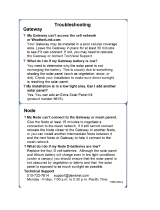
Figure 1. ISM radio board
A - Antenna connector
B - Button
C - LED
D1 - DIP switches
D2 - DIP Switches
Typically, users will not need to adjust the DIP switch
settings on the physical radio modules.
For the DXM1200 models, set the radio options using the
LCD menu.
Button Operation
For DXM models without a LCD display, use the button (B) to bind the ISM radio. For models with a LCD display,
use the ISM menu to bind the radio.
LED Operation
The LED located on the ISM radio module indicates power and communications traffic. ISM board LED operations
also display on the LED on the right side of the I/O base board.
• Solid green DX80 ISM radio LED indicates power.
• Flashing green MultiHop ISM radio LED indicates operation.
• Red and green combined: Communications traffic and binding.
2.2 DIP Switch Settings for the MultiHop HE5 Board Module
D1 Switches D2 Switches
Device Settings 1 2 3 4 1 2 3 4
Serial line baud rate 19200 OR User defined receiver
slots
OFF* OFF*
Serial line baud rate 38400 OR 32 receiver slots OFF ON
Serial line baud rate 9600 OR 128 receiver slots ON OFF
Serial line baud rate Custom OR 4 receiver slots ON ON
Parity: None OFF* OFF*
Parity: Even OFF ON
Parity: Odd ON OFF
Disable serial (low power mode) and enable the receiver
slots select for switches 1-2
ON ON
DXM150-Sx Wireless Modbus Slave
www.bannerengineering.com - Tel: + 1 888 373 6767 5

D1 Switches D2 Switches
Device Settings 1 2 3 4 1 2 3 4
Transmit power
900 MHz radios: 1.00 Watt (30 dBm)
2.4 GHz radios: 0.065 Watts (18 dBm) and 60 ms
frame
OFF*
Transmit power
900 MHz radios: 0.25 Watts (24 dBm)
2.4 GHz radios: 0.065 Watts (18 dBm) and 40 ms
frame
ON
Application mode: Modbus OFF*
Application mode: Transparent ON
MultiHop radio setting: Repeater OFF* OFF*
MultiHop radio setting: Master OFF ON
MultiHop radio setting: Slave ON OFF
MultiHop radio setting: Reserved ON ON
* Default configuration
2.2.1 Application Mode
The MultiHop radio operates in either Modbus mode or transparent mode. Use the internal DIP switches to select the mode
of operation. All MultiHop radios within a wireless network must be in the same mode.
Modbus mode uses the Modbus protocol for routing packets. In Modbus mode, a routing table is stored in each parent
device to optimize the radio
traffic. This allows for point to point communication in a multiple data radio network and
acknowledgement/retry of radio packets. To access a radio's I/O, the radios must be running in Modbus mode.
In transparent application mode, all incoming packets are stored, then broadcast to all connected data radios. The data
communication is packet based and not
specific to any protocol. The application layer is responsible for data integrity. For
one to one data radios it is possible to enable broadcast acknowledgement of the data packets to provide better
throughput. In transparent mode, there is no access to the radio's I/O.
2.2.2 Baud Rate and Parity
The baud rate (bits per second) is the data transmission rate between the device and whatever it is physically wired to. Set
the parity to match the parity of the device you are wired to.
2.2.3 Disable Serial
Disable an unused local serial connection to reduce the power consumption of a data radio powered from the solar
assembly or from batteries. All radio communications remain operational.
2.2.4 Transmit Power Levels/Frame Size
The 900 MHz data radios can be operated at 1 watt (30 dBm) or 0.250 watt (24 dBm). For most models, the default transmit
power is 1 watt.
For 2.4 GHz radios, the transmit power is
fixed at 0.065 watt (18 dBm) and DIP switch 5 is used to set the frame timing. The
default position (OFF) sets the frame timing to 60 milliseconds. To increase throughput, set the frame timing to 40
milliseconds.
Important: Prior to date code 15341 and radio
firmware version 3.6, the frame timing was 40 ms (OFF) or
20 ms (ON).
DXM150-Sx Wireless Modbus Slave
6 www.bannerengineering.com - Tel: + 1 888 373 6767

2.3 Binding the ISM Radio of a Modbus Slave
A DXM (for example, model DXM1x0-S*R2) contains two boards: a MultiHop ISM radio and an I/O base board. Each board
is a separate Modbus device and requires a unique Modbus ID.
• The ISM radio is not required to have a Modbus ID because there are no registers to manage, but it generally does
have a Modbus ID assigned to it.
• The I/O board must have a Modbus ID to access the I/O register data and configuration data.
To bind the DXM (as either a repeater or slave radio) to its master radio, follow the MultiHop binding instructions. If the
binding instructions are not included in the master radio datasheet, refer to the MultiHop Quick Start Guide (p/n 152653) or
Instruction Manual (p/n 151317).
The ISM radio board's Modbus ID is assigned from the master radio during binding using the master radio's rotary dials or
the DXM Controller's LCD Binding menu. For example, if the master's binding number is 25, the DXM Slave ISM radio's
Modbus ID is set to 25.
By default, the I/O board's Modbus ID is set to 11. To change the Modbus ID, use the I/O board DIP switches. For
applications requiring Modbus IDs outside the range of the DIP switches, write a Modbus ID to a Modbus register on the I/O
board. (See Setting the Modbus Slave ID on the I/O Base Board on p. 16.)
Use the MultiHop
Configuration Software to display and configure a MultiHop radio network. With the DXM, only the ISM
radio displays on the Network View screen. The Modbus ID of the I/O board is a separate device that is not a part of the
radio network. Although the I/O board does not show up in the Network View, it is accessible when using the Register View
functions.
DXM150-Sx Wireless Modbus Slave
www.bannerengineering.com - Tel: + 1 888 373 6767 7

3 I/O Base Boards
3.1 Board Connections for the S1 Models
ON
1
A
B
D
C
E
F
J
L
L
G1
H
G2
G3
1
24
25
48
A
B
K
Figure 2. Board Connections
1 NC 17 Input 2B 33 Analog Output 1 (0 to 10 V)
2 12 to 30 V DC or solar power in (+) 18 Ground 34 Ground
3 Ground 19 Output 1 Normally Open 35 PWR Out - Jumper
4
Battery in (< 15 V dc) (must be a sealed lead
acid battery)
20 Output 1 Common 36 Ground
5 Ground 21 Output 1 Normally Closed 37 Universal Input 8
6 Primary RS-485 – 22 Output 3 Normally Open 38 Universal Input 7
7 Primary RS-485 + 23 Output 3 Common 39 Universal Input 6
8 Ground 24 Output 3 Normally Closed 40 Universal Input 5
9 Not used 25 NMOS Output 5 41 Ground
10 Not used 26 No connection 42 Universal Input 4
11 Not used 27 NMOS Output 6 43 Universal Input 3
12 Not used 28 NMOS Output 7 44 Ground
13 Ground 29 No connection 45 PWR Out - Jumper
14 Input 1A 30 NMOS Output 8 46 Universal Input 2
15 Input 1B 31 Ground 47 Universal Input 1
16 Input 2A 32 Analog Output 2 (0 to 10 V) 48 Ground
A Base Board LED E PWR Out Jumpers G3
Analog Output Characteristics Jumpers
(Jumper 1 sets analog out 1, jumper 2 sets
analog out 2)
B Not Used F Radio Binding Button H ISM Radio Connection
C Radio LED G1 Not Used J Modbus Slave ID DIP Switches
D Radio Module Antenna G2 Not Used K Rotary Dials
L SAM4 Processor Board Connection
DXM150-Sx Wireless Modbus Slave
8 www.bannerengineering.com - Tel: + 1 888 373 6767

3.2 Board Connections for the S2 Models
ON
1
1
1
B
D
48
25
1
24
E
L
A
L
C
F
K
J
H
G3
G1
G2
B
A
RTCT
485S
VC
1
232
CAN
2
1
2
1
1
1
Figure 3. Board Connections
********* THIS IS THE TABLE FOR THE DXM150-B2. PLEASE MARK THIS UP FOR THE DXM150-S2. *********
1
NC 17 Input 2B 33 Analog Output 1 (0–20 mA or 0–10 V)
2 12 to 30 V DC or solar power in (+) 18 Ground 34 Ground
3 Ground 19 Output 1 PNP/NPN 35 PWR Out - Jumper
4
Battery in (< 15 V dc) (must be a sealed lead
acid battery)
20 Output 2 PNP/NPN 36 Ground
5 Ground 21 Output 3 PNP/NPN 37 Universal Input 8
6 Primary RS-485 – 22 Output 4 PNP/NPN 38 Universal Input 7
7 Primary RS-485 + 23 PWR Out OR 39 Universal Input 6
8 Ground 24 Ground 40 Universal Input 5
9 RS-232 Tx / CAN 25 Ground 41 Ground
10 RS-232 Rx / CAN 26 PWR OUT OR 42 Universal Input 4
11 Secondary RS-485 – or RS-232 RXRDY 27 Output 8 PNP/NPN 43 Universal Input 3
12 Secondary RS-485 + or RS-232 TXRDY 28 Output 7 PNP/NPN 44 Ground
13 Ground 29 Output 6 PNP/NPN 45 PWR Out - Jumper
14 Input 1A 30 Output 5 PNP/NPN 46 Universal Input 2
15 Input 1B 31 Ground 47 Universal Input 1
16 Input 2A 32
Analog Output 2 (0–20 mA or 0–10
V)
48 Ground
A Base Board LED E PWR Out Jumpers G3
Analog Output Characteristics Jumpers
(Jumper 1 sets analog out 1, jumper 2 sets
analog out 2)
B Cellular Antenna F Radio Binding Button H ISM Radio Connection
DXM150-Sx Wireless Modbus Slave
www.bannerengineering.com - Tel: + 1 888 373 6767 9

C Radio LED G1 RS-485 Jumpers J Modbus Slave ID DIP Switches
D Radio Module Antenna G2 RS-232 Jumpers K Rotary Dials
L SAM4 Processor Board Connection
3.3 DIP Switches for the I/O Board
The DXM150-Sx Wireless Modbus Slave I/O board DIP switches are set from the factory to Modbus Slave ID 11.
3.4 I/O Board Jumpers
Hardware jumpers on the DXM I/O board allow the user to select alternative pin operations. Turn the power off to the device
before changing jumper positions.
Jumper
Function Positions
E Courtesy power output Jumper 2 is the power jumper for pin 45. Jumper 1 is the power jumper for pin 35.
• The pin 45 jumper selects 2.7 V when in the "a" position and 12 V battery in the
"b" position.
• The pin 35 jumper selects 4.2 V when in the "a" position and device power on
pin 2 in the "b" position.
G1 RS-485 Modbus Slave or
RS-232 Flow Control
Defines the operation of pins 11 and 12. Set the jumpers to use pins 11 and 12 as a
secondary Modbus RS-485 slave port or flow control pins for the RS-232 port. Both
jumpers must be set to the same operation, RS-485 Modbus Slave or Flow control.
The default setting is RS-485.
G2 Generic RS-232 Serial Port or
CAN Serial Port
Defines the operation of pins 9 and 10. Set the jumpers to use pins 9 and 10 as a CAN
serial port or a generic RS-232 serial port. Both jumpers must be set to the same
operation, CAN or RS232.
The default setting is CAN serial port.
G3 Analog output characteristics
for AO2 (pin 32) and AO1 (pin
33)
Defines current (0–20 mA) or voltage (0–10 V) for analog output 1 and 2.
By default, current (0–20 mA) is selected using jumpers 1 and 2 and registers 4008 and
4028 contain a value of 2.
To select voltage (0–10 V) for output Aout1, set jumper 1 in the voltage position (V) and
set Modbus register 4008 on the I/O board (SID 200) to 3.
To select voltage (0–10 V) for output Aout2, set jumper 2 in the voltage position (V) and
set Modbus register 4028 on the I/O board (SID 200) to 3.
3.5 Applying Power to the S1 Model
Apply power using either 12 to 30 V DC or a 12 V DC solar panel and 12 V sealed lead acid battery.
Pin Description
Pin 1 No connection
Pin 2 12 to 30 V DC input (+) or solar panel connection (+)
Pins 3, 5, 8, 13, 18, 31, 34,
36, 41, 44, 48
Main logic ground for the DXM150-S1
Pin 4 Solar or backup battery positive input. Battery voltage must be less than 15 V dc. Use only a sealed lead acid (SLA)
battery.
Pin 35, Pin 45 These outputs are controlled by hardware jumpers.
Jumper 2 is the power jumper for pin 45. Jumper 1 is the power jumper for pin 35. Refer to the wiring board for more
information.
• The pin 45 jumper selects 2.7 V when in the "a" position and 12 V battery in the "b" position.
• The pin 35 jumper selects 4.2 V when in the "a" position and device power on pin 2 in the "b" position.
DXM150-Sx Wireless Modbus Slave
10 www.bannerengineering.com - Tel: + 1 888 373 6767

3.6 Applying Power to the B2 or S2 Models
Apply power using either 12 to 30 V DC or a 12 V DC solar panel and 12 V sealed lead acid battery.
Pin Description
Pin 1 No connection
Pin 2 12 to 30 V DC input (+) or solar panel connection (+)
Pins 3, 5, 8, 13, 18, 24, 25,
31, 34, 36, 41, 44, 48
Main logic ground for the DXM
Pin 4 Solar or backup battery positive input. Battery voltage must be less than 15 V dc. Use only a sealed lead acid (SLA)
battery.
Pin 23, Pin 26 Courtesy power output from either the input power from pin 2 or the battery power from pin 4.
3.7 Supplying Power from a Solar Panel
To power the DXM150-Sx Wireless Modbus Slave from a 12 V dc solar panel, connect the solar panel to power pins 2(+)
and 3(-). Connect a 12 V dc sealed lead acid (SLA) rechargeable battery to pins 4(+) and 5(-).
The factory default setting for the battery charging configuration assumes you are using 12 to 30 V DC power to recharge
the battery. If the incoming power is from a solar panel, you must change the charging
configuration.
The battery charging configuration defaults to a battery backup configuration. To change the charging configuration from
the menu system:
1. From the DXM LCD menu, navigate to System Config > I/O Board > Charger.
2. Select Solar for solar panel configurations or DC for battery backup configurations.
To change the charging configuration by writing to Modbus register 6071 on the I/O base board (Slave ID 11):
1. Write a 0 to select the solar power charging configuration.
3.8 Connecting a Battery
When attaching a battery to the DXM as a backup battery or as a solar battery, verify the charging algorithm is set properly.
The factory default setting for the battery charging algorithm assumes you are using 12 to 30 V DC to recharge the battery.
The charging algorithm is designed to work with a sealed lead acid (SLA) battery only.
• When using 12 to 30 V DC, connect the 12 to 30 V DC + to pin 2 and connect the ground to pin 3.
• When using main dc power with a back up battery (default configuration), connect the incoming main power pin 2
(+) and to pin 3 (-). Connect the 12 V sealed lead acid battery to pin 4 (+) and pin 5 (-). The incoming main power
must be 15 to 30 V dc to charge the battery.
3.9 Connecting the Communication Pins
The base board communications connection for external Modbus device uses the primary RS-485.
RS-485. The primary RS-485 bus is a common bus shared with the ISM radio board (Modbus Slave ID 1).
RS-232. The RS-232 bus is not currently defined.
Pin
Parameter Description
Pin 6 Primary RS-485 – Use this bus to connect other Modbus Slave devices into the wireless network.
Modbus Register 6101 = Baud Rate
0 = 19.2k
1 = 9600
2 = 38400
Modbus Register 6103 = Parity
0 = no parity
1 = odd
2 = even
Pin 7 Primary RS-485 +
DXM150-Sx Wireless Modbus Slave
www.bannerengineering.com - Tel: + 1 888 373 6767 11

Pin Parameter Description
Pin 9 RS-232 Tx
Serial RS-232 connection. This bus must use a ground connection between devices to operate
correctly.
Pin 10 RS-232 Rx
Pin 13 Secondary RS-485 –
Not used
Pin 14 Secondary RS-485 +
Pin 15 CANL –
Pin 16 CANH +
3.10 Inputs and Outputs
The I/O base board is a Modbus slave device that communicates using Modbus commands. Refer to the Modbus Registers
section for more descriptions of each Modbus register on the DXM150-Sx Wireless Modbus Slave.
3.10.1 Isolated Discrete Inputs
The DXM has two (2) optically isolated inputs. The inputs signals are electrically isolated forming a barrier to protect the
DXM from different ground potentials of the input signals. Input 1 uses terminals 1A and 1B and the second input uses 2A
and 2B. An input voltage should be applied between the terminals between 0 and 30 V dc, the on/off transition threshold is
approximately 2.6v
Pin Input Description
Pin 14 Input 1A
Optically isolated AC input type, 0 to 12 to 30 V DC
Input to output isolation of 2.5 kV
IN xA
IN xB
Pin 15 Input 1B
Pin 16 Input 2A
Pin 17 Input 2B
Synchronous Counters—An isolated input can be programmed to count the input signal transitions. When an input is
enabled as a counter, the counter value is stored into two 16-bit Modbus registers for a total count of 32-bits (unsigned). To
program an input to capture the edge transition counts, follow Example:
Configure Input 1 as a Synchronous Counter on p.
13.
The counters are synchronous because the inputs are sampled at a 10 ms clock rate. The input logic does not detect rising
or falling edges, it samples the input every 10 ms to
find level changes. The input signals must be high or low for more than
10 ms or the input will not detect transitions. Because most signals are not perfect, a realistic limit for the synchronous
counter would be 30 to 40 Hz.
Universal inputs can also be
configured as a synchronous counter. See Modbus Register Summary on p. 17 for all the
register definitions. The procedure for creating a synchronous counter is the same as a isolated input with the addition of
changing the input type to PNP or NPN.
3.10.2 Universal Inputs
The universal inputs can be programmed to accept different types of inputs: discrete NPN/PNP, 0 to 20 mA analog, 0 to 10
V analog, 10k thermistor, potentiometer sense, bridge, and NPN raw fast. Use the DXM
Configuration Software tool to write
to the appropriate Modbus registers in the I/O board to configure the input type.
The universal inputs are treated as analog inputs. When the universal inputs are defined as mA, V, or temperature, use
Modbus registers to configure the operational characteristics of the inputs. These parameters are temperature conversion
type, enable full scale, threshold and hysteresis. See Modbus Register Summary on p. 17 for the parameter
definitions.
When a universal input is configured as an NPN or PNP input type, it can be enabled to be a synchronous counter. Enable
the counter function by setting Modbus register 'Enable Rising' or 'Enable Falling' to 1. See Modbus Register Summary on
p. 17 for the universal input register
definitions.
DXM150-Sx Wireless Modbus Slave
12 www.bannerengineering.com - Tel: + 1 888 373 6767

Pin Univ. Input Description
Pin 47 Universal Input 1 Program the universal inputs to accept input types NPN, PNP, 10k thermistor, 0 to 10 V, 0 to
20 mA, or potentiometer. The default setting is 8: NPN raw fast. To set the input type, write the
following values to the Input Type Modbus registers.
0 = NPN
1 = PNP
2 = 0 to 20 mA
3 = 0 to 10 V dc
4 = 10k Thermistor
5 = Potentiometer Sense (DXM150 only)
6 = Not used
7 = Bridge
8 = NPN Raw Fast (default)
Pin 46 Universal Input 2
Pin 43 Universal Input 3
Pin 42 Universal Input 4
Pin 40 Universal Input 5
Pin 39 Universal Input 6
Pin 38 Universal Input 7
Pin 37 Universal Input 8
Bridge Input
The bridge input is not implemented yet.
NPN vs NPN Raw Fast
The difference between NPN and NPN Raw Fast is the amount of settling time given to the input. Switch the input
type to NPN if the input is not detecting a transition.
Potentiometer Sense (DXM150 only)
A potentiometer input is created from two inputs: a voltage source (pin 45) that supplies a voltage to the
potentiometer and an input sense (Potentiometer Sense) to read the resistance. See Using Universal Iwnputs to
Read a Potentiometer (p/n b_4462775) for more information.
Thermistor Input
A thermistor input must use a 10k thermistor between ground and the universal input. The thermistor must be a 10k
NTC (Banner model number BWA-THERMISTOR-002) or equivalent. Select the temperature conversion of degrees
C (default) or degrees F by writing to the Modbus registers defined in
I/O Base Board
.
Example: Configure Input 1 as a Synchronous Counter
1. Connect the DXM to the PC.
2. Launch the DXM
Configuration Software software.
3. Connect to the DXM by selecting the Device > Connection Settings menu option. You may connect using either
USB or Ethernet.
4. Select a COMM port from the drop-down list and click Connect.
5. Click on the Register View tab on the left part of the page.
6. Change the Source Register selection to I/O Board Registers.
7. In the Write Registers area, write Modbus register 4908 to 1 to enable counting on the rising edge of the input
signal.
8. Read Modbus registers 4910 and 4911 to get the 32-bit value of the count.
Example: Change Universal Input 2 to a 0 to 10 V dc Input
1. Connect the DXM to the PC.
2. Launch the DXM
Configuration Software software.
3. Connect to the DXM by selecting the Device > Connection Settings menu option. You may connect using either
USB or Ethernet.
4. Select a COMM port from the drop-down list and click Connect.
5. Click on the Register View tab on the left part of the page.
6. Change the Source Register selection to I/O Board Registers.
7. Write a 3 to Modbus register 3326 on Modbus Slave ID 11 (I/O board).
8. Cycle power to the device.
9. Using the Register View tab, read register 3326 to verify it is set to 3.
Example: Change Analog Output 1 to a 0 to 10 V dc Output
1. Connect the DXM to the PC.
DXM150-Sx Wireless Modbus Slave
www.bannerengineering.com - Tel: + 1 888 373 6767 13

2. Launch the DXM Configuration Software software.
3. Connect to the DXM by selecting the Device > Connection Settings menu option. You may connect using either
USB or Ethernet.
4. Select a COMM port from the drop-down list and click Connect.
5. Click on the Register View tab on the left part of the page.
6. Change the Source Register selection to I/O Board Registers.
7. Set jumper 1 on the I/O base board to the 0 to 10 V position. Refer to the base board image for the analog output
jumper position.
8. Write a 3 to Modbus register 4008 on Modbus Slave ID 11 (I/O board).
9. Cycle power to the device.
10. Using the Register View tab, read register 4008 to verify it is set to 3.
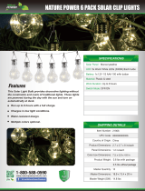
Example: Change Universal Input 8 to Read a Potentiometer Input
2.7 V
4.2 V
Power pin 45
Ground
Pot sense Ui8
pin 35
Pwr In
pin 45
Vbatt
1
2
3
4
5
6
Figure 4. Default jumper position
1. Launch the DXM Configuration Software tool.
2. Click on the Register View tab on the left part of the page.
3. In the upper right part of the window select Modbus Registers using Modbus Slave ID radio button and enter
Modbus Slave ID 11.
4. To set universal input 8 as the sense, write Modbus register 3446 with 5 (Potentiometer Sense).
5. Verify the jumpers are still set to their default position. One jumper should be on pins 1 and 3 to get a 2.7 V source
voltage out pin 45. The default position of the other jumper is on pins 4 and 6.
6. Connect one potentiometer side to power output (pin 45), connect the tap point of the pot to universal input 8 (pin
37), and connect the other end of the pot to ground (pin 36).
3.10.3 PNP and NPN Outputs for the B1, B2, and S2 Models
Pin Output Modbus
Register
Description PNP OUT Wiring NPN OUT Wiring
19 1 501 PNP/NPN Output 1
Discrete OUT
GND
PWR
10-30V dc
Load
dc common
Load
Discrete OUT
GND
PWR
10–30 V dc
dc common
20 2 502 PNP/NPN Output 2
21 3 503 PNP/NPN Output 3
22 4 504 PNP/NPN Output 4
30 5 505 PNP/NPN Output 5
29 6 506 PNP/NPN Output 6
28 7 507 PNP/NPN Output 7
27 8 508 PNP/NPN Output 8
DXM150-Sx Wireless Modbus Slave
14 www.bannerengineering.com - Tel: + 1 888 373 6767

3.10.4 NMOS Outputs for the S1 Models
Pin Output Description Wiring
Pin 25
NMOS Discrete
Outputs
Less than 1 A maximum current at 30 V DC
ON-State Saturation: Less than 0.7 V at 20 mA
ON Condition: Less than 0.7 V
OFF Condition: Open
Output
Pin 27
Pin 28
Pin 30
3.10.5 Relay Outputs for the S1 Models
Pin
Output Description Wiring
Pin 19 Output 1: Normally Open
SPDT (Form C) relay, 250 V AC, 16 A
Normally open
Common
Normally closed
Pin 20 Output 1: Common
Pin 21 Output 1: Normally Closed
Pin 22 Output 3: Normally Open
Pin 23 Output 3: Common
Pin 24 Output 3: Normally Closed
3.10.6 Analog Outputs (DAC)
The following characteristics are configurable for each of the analog outputs.
Pin
Output Description
Pin 33 Analog Output 1 0 to 20 mA or 0 to 10 V dc output (selectable using the Analog Output Characteristics Jumpers)
Accuracy: 0.1% of full scale +0.01% per °C
Resolution: 12-bit
Pin 32 Analog Output 2
DXM150-Sx Wireless Modbus Slave
www.bannerengineering.com - Tel: + 1 888 373 6767 15

4 Additional Information
4.1 Setting the Modbus Slave ID on the I/O Base Board
Only DXM150-Sx and SxR2 Modbus Slave models require that the Modbus Slave ID to be adjusted on the I/O base board.
The DXM150-Sx Wireless Modbus Slave devices use DIP switch J and rotary dial K to set the Modbus slave ID. The device
can use a Modbus register 6804 in the I/O board to access the full range of Modbus Slave IDs.
On the DXM150-Sx Wireless Modbus Slave models, use rotary dial K to select the lower digit of the Modbus Slave ID.
4.1.1 DXM150-Sx Wireless Modbus Slave Models
DIP Switch location J
defines the course group of Modbus Slave IDs. DIP Switch 4 must be set to ON for DXM1
xx
-Sx and
DXM1
xx
-SxR2 models.
Settings
Location J DIP Switches
1 2 3 4
Modbus Slave ID set to 11 through 19 OFF OFF
Modbus Slave ID set to 20 through 29 ON OFF
Modbus Slave ID set to 30 through 39 OFF ON
Modbus Slave ID set to 40 through 49 ON ON
Not Used -
Modbus Slave Configuration (S1 model only)
1
ON
I2C Processor Communication OFF
Rotary dial location K and DIP Switch location J set the Modbus Slave IDs.
DIP Switches J Location K Rotary Dials — Position 0 through 9
1 2 0 1 2 3 4 5 6 7 8 9
OFF OFF x
2
11 12 13 14 15 16 17 18 19
ON OFF 20 21 22 23 24 25 26 27 28 29
OFF ON 30 31 32 33 34 35 36 37 38 39
ON ON 40 41 42 43 44 45 46 47 48 49
DXM150-Sx Wireless Modbus Slave Example
To set the DXM150-Sx Wireless Modbus Slave to a Modbus Slave ID of 25, set the following:
Location J DIP switches set to: 1= ON, 2=OFF
Rotary dial set to 5
The DIP switch sets the upper digit of the slave ID to 2 while the rotary dial sets the lower digit to 5.
4.1.2 Setting the DXM I/O Board Modbus Slave ID using Modbus
Registers
Write to the I/O board's Modbus register 6804 to set the Modbus Slave ID to any valid Modbus Slave ID (1 through 245).
• For the DXM150-Sx Wireless Modbus Slave model, rotary dial K should be in the zero position to use the Modbus
register slave ID.
1
Must be in the ON position for the -S1 model)
2
Uses value in Modbus register 6804.
DXM150-Sx Wireless Modbus Slave
16 www.bannerengineering.com - Tel: + 1 888 373 6767

4.2 Modbus Register Summary
4.2.1 Modbus Registers
The DXM150-S1 and S2 devices can have two Modbus IDs: one for the MultiHop ISM radio (by default, set to 1) and one for
the I/O base (by default, set to 11).
All Modbus registers are
defined as 16-bit Modbus Holding Registers. When connecting additional Modbus slave devices,
only use Modbus IDs 11 through 60. The master device can be expanded to use Modbus IDs 2 through 198 with
modifications to the Master radio settings.
4.2.2 Modbus Registers for the -x1 Model I/O Board
By default, the I/O board Modbus ID is 11 for the DXM150-x1 models.
Base Board Input Connection
Modbus Register Description
1 Isolated discrete input 1 (1A and 1B)
2 Isolated discrete input 2 (2A and 2B)
3 Universal input 1
4 Universal input 2
5 Universal input 3
6 Universal input 4
7 Universal input 5
8 Universal input 6
9 Universal input 7
10 Universal input 8
Base Board Output Connection
Modbus Register Description
501 Relay 1
502 Not used
503 Relay 2
504 Not used
505 NMOS Output 5
506 NMOS Output 6
507 NMOS Output 7
508 NMOS Output 8
509 DAC Output 1
510 DAC Output 2
4.2.3 Modbus Registers for the -x2 I/O Board
By default, the I/O board Modbus ID is 11 for the DXM150-x1 models.
Base Board Input Connection
Modbus Register Description
1 Optically isolated input 1
2 Optically isolated input 2
3 Universal input 1
4 Universal input 2
5 Universal input 3
6 Universal input 4
7 Universal input 5
8 Universal input 6
9 Universal input 7
10 Universal input 8
Base Board Output Connection
Modbus Register Description
501 PNP/NPN Output 1
502 PNP/NPN Output 2
503 PNP/NPN Output 3
504 PNP/NPN Output 4
505 PNP/NPN Output 5
506 PNP/NPN Output 6
507 PNP/NPN Output 7
508 PNP/NPN Output 8
509 DAC Output 1
510 DAC Output 2
DXM150-Sx Wireless Modbus Slave
www.bannerengineering.com - Tel: + 1 888 373 6767 17

Board Output Settings
Register Description Values Register Description
3704 Enable Discrete Output 1 0 = NPN; 1 = PNP 3705 Invert Output
3724 Enable Discrete Output 2 0 = NPN; 1 = PNP 3725 Invert Output
3744 Enable Discrete Output 3 0 = NPN; 1 = PNP 3745 Invert Output
3764 Enable Discrete Output 4 0 = NPN; 1 = PNP 3765 Invert Output
3784 Enable Discrete Output 5 0 = NPN; 1 = PNP 3785 Invert Output
3804 Enable Discrete Output 6 0 = NPN; 1 = PNP 3805 Invert Output
3824 Enable Discrete Output 7 0 = NPN; 1 = PNP 3825 Invert Output
3844 Enable Discrete Output 8 0 = NPN; 1 = PNP 3845 Invert Output
For example, to change between PNP/NPN outputs, set parameter register 3704 to 0 for NPN and 1 for PNP.
4.2.4 Modbus Configuration Registers for the Discrete and Universal
Inputs
Modbus configuration registers are identified below. The configuration software creates a graphical view of the I/O board
parameters. This allows for easy and quick configuration of the I/O board parameters.
For the DXM150-Bx models, use the DXM Configuration Software to configure the registers using the Local Registers >
Local Registers in Use > Edit Registers screen.
For the DXM150-Sx models, a DXM Master radio is required to access the remote modbus slave device and
configure the
Discrete and Universal Inputs. Manually write to these modbus registers to set parameters or configure the input
parameters using the
Configuration > Configure Device > Inputs screen of the Multihop Configuration Software..
Register Isolated Discrete Input 1
3013 Enable rising edge counter
3014 Enable falling edge counter
3015 High register for counter
3016 Low register for counter
Register Isolated Discrete Input 2
3033 Enable rising edge counter
3034 Enable falling edge counter
3035 High register for counter
3036 Low register for counter
Universal Input Parameter Modbus Registers
Universal Inputs 1 2 3 4 5 6 7 8
Enable Full Scale 3303 3323 3343 3363 3383 3403 3423 3443
Temperature °C/°F 3304 3324 3344 3364 3384 3404 3424 3444
Input Type 3306 3326 3346 3366 3386 3406 3426 3446
Threshold 3308 3328 3348 3368 3388 3408 3428 3448
Hysteresis 3309 3329 3349 3369 3389 3409 3429 3449
Enable Rising 4908 4928 4948 4968 4988 5008 5028 5048
Enable Falling 4909 4929 4949 4969 4989 5009 5029 5049
High Register for Counter 4910 4930 4950 4970 4990 5010 5030 5050
Low Register for Counter 4911 4931 4951 4971 4991 5011 5031 5051
DXM150-Sx Wireless Modbus Slave
18 www.bannerengineering.com - Tel: + 1 888 373 6767

Universal Input Register Ranges
Register Types Unit Minimum Value Maximum Value
Discrete input/output 0 1
Universal input 0 to 10 V mV 0 10000 *
Universal input 0 to 20 mA µA 0 20000 *
Universal input temperature (–40 °C to +85 °C) C or F, signed, in tenths of a degree –400 850
Universal potentiometer unsigned 0 65535
* Setting Enable Full Scale to 1 sets the ranges to a linear scale of 0 to 65535.
4.2.5 Modbus Configuration Registers for the I/O (Definitions)
Enable Full Scale
Set to 1 to enable a linear range from 0 to 65535 for
specified input range. For a 4 to 20 mA input, a value of 0
represents 4 mA and 65535 represents 20 mA. Set this parameter to 0 to store input readings in unit-specific data.
For example, the register data representing a 15.53 mA reading is 15530. For units of current (0 to 20 mA inputs),
values are stored as µA (micro Amps) and voltage values are stored as mV (millivolts).
Enable Rising/Falling
Use these registers to enable the universal input logic to count on a rising transition or a falling transition. Write a
one (1) to enable; write a zero (0) to disable.
High/Low Register for Counter
The low and high registers for the counter hold the 32-bit counter value. To erase the counter, write zeroes to both
registers. To preset a counter value, write that value to the appropriate register.
Hysteresis and Threshold
Threshold and hysteresis work together to establish the ON and OFF points of an analog input. The threshold
defines a trigger point or reporting threshold (ON point) for a sensor input. Setting a threshold establishes an ON
point. Hysteresis
defines how far below the threshold the analog input is required to be before the input is
considered OFF. A typical hysteresis value is 10% to 20% of the unit’s range.
Threshold
ON point
Time
Input Value
Input
Hysteresis
OFF point
In the example shown, the input is considered on at 15 mA. To
consider the input off at 13 mA, set the hysteresis to 2 mA. The
input will be considered off when the value is 2 mA less than the
threshold.
Input Type
Program the universal inputs to accept input types NPN, PNP, 10k thermistor, 0 to 10 V, 0 to 20 mA, or
potentiometer. The default setting is 8: NPN raw fast. To set the input type, write the following values to the Input
Type Modbus registers.
0 = NPN
1 = PNP
2 = 0 to 20 mA
3 = 0 to 10 V dc
4 = 10k Thermistor
5 = Potentiometer Sense (DXM150 only)
6 = Not used
7 = Bridge
8 = NPN Raw Fast (default)
Temperature °C/°F
Set to 1 to represent temperature units in degrees Fahrenheit, and set to 0 (default) to represent temperature units
in degrees Celsius.
DXM150-Sx Wireless Modbus Slave
www.bannerengineering.com - Tel: + 1 888 373 6767 19

4.2.6 Modbus Configuration Registers for Power
To monitor the input power characteristics of the DXM, read the following power Modbus registers. The on-board thermistor
is not calibrated, but can be used as a non-precision temperature input.
Modbus Register Description
6071 Battery backup charging algorithm.
0 = Battery is recharged from a solar panel
1 = Battery is recharged from 12 to 30 V dc . (default)
6081 Battery voltage (mV)
6082 Battery charging current (mA)
6083 Incoming supply voltage (mV) (solar or power supply)
6084 On-board thermistor temperature (⁰C)
Battery voltage
If no battery is present, the value in this register is less than 5 V. If the value in this register is greater than the
incoming voltage register, the battery is powering the system.
Battery charging current
The charging
configuration charges the battery when the incoming voltage register value is greater than the battery
voltage register value. This registers shows the charging current in milliamps.
Incoming supply voltage
The incoming power can be from a solar panel or from a power supply. The battery is charging when the incoming
voltage register value is greater than the battery voltage register value. The battery is powering the system when
the incoming voltage register value is less than the battery voltage register value.
On-board thermistor temperature
A thermistor measures the temperature of the solar controller board and its surrounding area and uses the
temperature as part of the battery charge calculations. This register stores the thermistor reading in tenths of
degrees C. This is not a calibrated input: divide by 10 to calculate the temperature in degrees C.
For calibrated temperature inputs,
define one of the universal inputs as a temperature input.
4.3 Working with Solar Power
A reliable solar system requires careful planning and monitoring to size the components correctly. The recommendations
provided are for the DXM system as an autonomous system.
Adding extra components increases the power requirements and likely requires increasing the solar system components.
Depending upon the geographical location, the size of the solar panel and battery may vary.
4.3.1 Setting the DXM for Solar Power
By default, the DXM is set from the factory to charge a backup battery from a line power source.
For DXM models with an LCD, use the buttons and menu system to change the charging algorithm to solar power. Go to
System
Config > I/O Board > Charger. Use the up/down arrows to select Solar.
For DXM models without an LCD, use the configuration software to adjust the I/O board Modbus register 6071. Set the
register to 0 to select battery charging from a solar panel, and set to 1 to select battery charging from incoming 12 to 30 V
DC supply.
To minimize the power consumption (may not apply to all models):
• If Ethernet is not being used, save up to 25% of the consumed power by disabling Ethernet. Set DIP switch 1 to the
ON position on the processor board then reboot.
• Instead of powering external devices all the time, take advantage of the switched power mechanisms to turn off
devices when possible.
• Minimize the number of cellular transactions and the amount of data pushed across the cellular modem.
4.3.2 Solar Components
The components of a solar system include the battery and the solar panel.
DXM150-Sx Wireless Modbus Slave
20 www.bannerengineering.com - Tel: + 1 888 373 6767
/