
For more information, visit www.fmiproducts.com
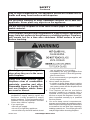
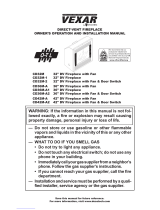
WARNING: If the information in this manual is not
followed exactly, a re or explosion may result causing
property damage, personal injury or loss of life.
— Do not store or use gasoline or other ammable
vapors and liquids in the vicinity of this or any other
appliance.
— WHAT TO DO IF YOU SMELL GAS
• Do not try to light any appliance.
• Do not touch any electrical switch; do not use any
phone in your building.
• Immediately call your gas supplier from a neighbor’s
phone. Follow the gas supplier’s instructions.
• If you cannot reach your gas supplier, call the re
department.
— Installation and service must be performed by a quali-
ed installer, service agency or the gas supplier.
INSTALLER: Leave this manual with the appliance.
CONSUMER: Retain this manual for future reference.
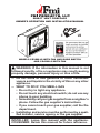
DIRECT VENT FIREPLACE
OWNER’S OPERATION AND INSTALLATION MANUAL
MODELS CD36M-LS WITH FAN AND DOOR SWITCH
AND CD42M-LS WITH FAN
PFS
®
USC

www.fmiproducts.com
125205-01E2
WARNING: Improper installation, adjustment, al-
teration, service or maintenance can cause injury or
property damage. Refer to this manual for correct in-
stallation and operational procedures. For assistance
or additional information consult a qualied installer,
service agency or the gas supplier.
WARNING: This direct vent gas replace is intended
for use with natural or propane/LP gas only. Do not at-
tempt to burn any solid fuels in this appliance.
This replace may be installed as an OEM installation
in a manufactured (mobile) home and must be installed
in accordance with the manufacturers instructions and
the Manufactured Home Construction and Safety Stan-
dard, Title 24 CFR, Part 3280 in the United States or the
Mobile Home Standard, CAN/CSA Z240 MH Series, in
Canada. This replace is only for use with the type(s)
of gas indicated on the rating plate. A conversion kit is
supplied with the replace.
State of Massachusetts: The installation must be made
by a licensed plumber or gas tter in the Commonwealth
of Massachusetts.
SAVE THIS BOOK
This book is valuable. In addition to instructing you on how to install and
maintain your appliance, it also contains information that will enable you to
obtain replacement parts or optional accessory items when needed. Keep
it with your other important papers.
TABLE OF CONTENTS
Introduction .......................................................... 3
Selecting Location ............................................... 3
Local Codes......................................................... 4
Safety .................................................................. 4
Product Features ................................................. 6
Pre-Installation Preparation .................................. 6
Requirements for the Commonwealth of
Massachusetts..................................................... 9
Installation ......................................................... 10
Burner Flame Adjustment .................................. 23
Operation ........................................................... 24
Gas Conversion ................................................. 26
Cleaning and Maintenance ................................ 27
Troubleshooting ................................................. 29
Specications .................................................... 33
Replacement Parts ............................................ 33
Service Hints ..................................................... 33
Technical Service............................................... 33
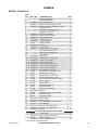
Parts .................................................................. 34
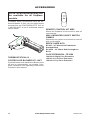
Accessories ....................................................... 38
Limited Two Year Warranty .................. Back Cover

www.fmiproducts.com
125205-01E 3
INTRODUCTION
WARNING: This product con-
tains and/or generates chemicals
known to the State of California
to cause cancer or birth defects
or other reproductive harm.
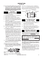
Model CD36M-LS and CD42M-LS is a heat
circulating gravity direct vent replace with
sealed combustion chamber. This replace
uses millivolt gas control valve and millivolt
ignition system.
This replace is convertible with the standard
setup as natural gas. Conversion may be per-
formed by the OEM mobile home builder or by
a qualied service person on-site. If you are
uncertain as to what gas your unit is equipped
for, please check the rating plate located in-
side of the appliance opening or consult your
mobile home supplier or your local distributor
of FMI PRODUCTS, LLC.
NOTICE: Check local building
codes for area requirements be-
fore installing this appliance.
BEFORE YOU BEGIN
Before beginning the installation of your
appliance, read these instructions through
completely.
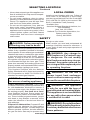
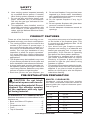
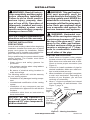
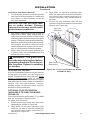
Figure 1 - Common Fireplace Locations
FULL
PROJECTION
CORNER
INSTALLATION
FLUSH
INSTALLATION
To determine the safest and most efcient
location for your replace, consider the fol-
lowing guidelines:
1. The location must allow for proper clear-
ances (see Figure 1).
• Flush installation is recommended where
living space is limited.
• Projected installation may be ideal for
a new addition to an existing nished
wall.
• Corner installation makes use of a space
that may not normally be used and pro-
vides a wider and more efcient range
for radiant heat transfer.
2. Consider a location where the replace
would not be affected by drafts, air con-
ditioning ducts, windows or doors.
3. A location that avoids the cutting of joists
or roof rafters makes ventilation installa-
tion easier.
This FMI PRODUCTS, LLC replace and its
components are safe when installed accord-
ing to this installation manual and operated as
recommended. Unless you use FMI PROD-
UCTS, LLC components designed and tested
for this replace system, YOU MAY CAUSE
A SAFETY HAZARD!
The FMI PRODUCTS, LLC warranty will
be voided by, and FMI PRODUCTS, LLC
disclaims any responsibility for the following
actions:
A) Modication to the replace, components,
doors, blower, fans or vent system.
B) Use of any component part not manufac-
tured or approved by FMI PRODUCTS,
LLC in combination with a FMI PROD-
UCTS, LLC replace system.
Proper installation is the most important step
in ensuring safe and continuous operation
of the replace. Consult the local building
codes as to the particular requirements
concerned with the installation of all factory
built replaces. This replace, when installed,
must be electrically grounded in accordance
with local codes or in the absence of local
codes, with the National Electrical Code,
ANSI/NFPA 70.
The installation must conform with local codes
or, in the absence of local codes, with the
National Fuel Gas Code, ANSI Z223.1. This
appliance complies with ANSI Z21.88.
SELECTING LOCATION
In selecting a location, the following precau-
tions must be observed:
• Do not connect this appliance to a chimney
system used for solid fuel burning replace.
• Due to high temperatures, do not locate
this appliance in high trafc areas or near
furniture and draperies.

www.fmiproducts.com
125205-01E4
SELECTING LOCATION
Continued
• Never obstruct openings of the appliance or
ow of ventilation air. Keep control compart-
ments accessible.
• Do not locate appliance close to where
gasoline or other ammable liquids may be
stored. The appliance must be kept clear
and free from combustible materials.
• Do not use this appliance if any part has
been under water. Immediately contact a
local service technician to examine the
appliance and to replace any part(s) of the
control ignition system and other related
components that have been submerged
under water.
LOCAL CODES
Install and use replace with care. Follow all
local codes. In the absence to local codes,
use the current National Fuel Gas Code ANSI
Z223.1/NFPA 54* (USA) or the current CSA-
B149.1 Installation Code (Canada).
*Available from:
American National Standards Institute, Inc.
1430 Broadway
New York, NY 10018
National Fire Protection Association, Inc.
Batterymarch Park
Quincy, MA 02269
SAFETY
DANGER: Carbon monoxide
poisoning may lead to death!
This replace must be installed by the O.E.M.
builder or by a qualied (certied or licensed)
service person. It has a sealed gas combustion
chamber that uses a coaxial pipe (pipe within
a pipe and having the same center) venting
system. It brings in fresh air for combustion
through the outer pipe and combustion gases
are exhausted through the inner pipe. If the
glass door assembly and venting pipe are not
properly seated, connected and sealed, carbon
monoxide leakage (spillage) can occur.
This fireplace complies with the National
Safety Standards and is listed and tested by
PFS Corporation to ANSI Z21.50/CSA 2.22
standard as vented gas replace.
NOTICE: Decorative product not
for use as a heating appliance.
Carbon Monoxide Poisoning: Early signs
of carbon monoxide poisoning resemble the
u, with headaches, dizziness or nausea. If
you have these signs, the replace may not
be working properly. Get fresh air at once!
Have replace serviced. Some people are
more affected by carbon monoxide than oth-
ers. These include pregnant women, people
with heart or lung disease or anemia, those
under the inuence of alcohol and those at
high altitudes.
Propane/LP & Natural Gas: Propane/LP and
natural gas are odorless. An odor-making
agent is added to the gas. The odor helps you
detect a gas leak. However, the odor added to
the gas can fade. Gas may be present even
WARNING: Any change to
this replace or it’s controls can
be dangerous. Do not modify
this replace under any circum-
stances. Any parts removed for
servicing must be replaced prior
to operating replace.
WARNING: Do not use a
blower insert, heat exchanger
insert or other accessory not ap-
proved for use with this replace.
WARNING: This appliance
is only for use with the type of
gas indicated on the rating plate.
This appliance is not convertible
for use with other gases unless
a certied kit is used.
WARNING: Do not allow fans
to blow directly into the replace.
Avoid any drafts that alter burner
ame patterns.
though no odor exists.
Make certain you read and understand all
warnings. Keep this manual for reference. It
is your guide to safe and proper operation of
this replace.

www.fmiproducts.com
125205-01E 5
SAFETY
Continued
Carefully supervise young chil-
dren when they are in the room
with replace.
Keep the area around your
replace clear of combustible
materials, gasoline and other
ammable vapor or liquids. Do
not run replace where these
are used or stored.
1. For propane/LP replace, do not place
propane/LP supply tank(s) inside any
structure. Locate propane/LP supply
tank(s) outdoors. To prevent performance
problems, do not use propane/LP fuel tank
of less than 100 lbs. capacity.
2. If you smell gas
• shut off gas supply
• do not try to light any appliance
• do not touch any electrical switch; do not
use any phone in your building
• immediately call your gas supplier from
a neighbor’s phone. Follow the gas sup-
plier's instructions
• if you cannot reach you gas supplier, call
the re department.
3. Never install the replace
• in windy or drafty areas where curtains
or other combustible (ammable) objects
can make contact with the replace front
• in high trafc areas
4. Turn fireplace off and let cool before
servicing, installing or repairing. Only a
qualied service person should install,
service or repair this replace. Have re-
place inspected annually by a qualied
service person.
5. You must keep control compartments,
burners and circulating air passages clean.
More frequent cleaning may be needed due
to excessive lint and dust from carpeting,
bedding material, etc. Turn off the gas valve
and pilot light before cleaning replace.
Due to high temperatures, the appliance should be located out of
trafc and away from furniture and draperies.
Do not place clothing or other ammable material on or near the
appliance. Never place any objects on the appliance.
Do not use this replace to cook food or burn paper or other am-
mable material.
This replace reaches high temperatures. Keep children and adults
away from hot surface to avoid burns or clothing ignition. Fireplace
will remain hot for a time after shutdown. Allow surface to cool
before touching.

www.fmiproducts.com
125205-01E6
PRODUCT FEATURES
These are a few facts that can help you un-
derstand and enjoy your direct-vent replace:
• The venting system may be routed to the
outside of your home in several ways. It
may vent through the roof (vertical) or it
may vent to an outside/exterior wall (hori-
zontal). The vent pipe installation is very
important to allow for proper operation.
You must follow the venting instructions
very carefully for either vertical or horizontal
applications.
• This replace may be installed in any room
of your house provided all local codes and
these installation instructions are followed.
• A piezo ignitor and ceramic electrode cre-
ate spark to ignite the pilot light. It does not
require any matches, batteries or any other
sources of ignition to light the pilot.
• Each time you turn on your replace, you
may notice some amount of condensation
on the inside of the replace glass. This
is normal and will disappear after 10-20
minutes of operation.
• Your direct-vent gas fireplace system
(replace and venting) is a balanced and
sealed gas operating unit. It requires ap-
proximately 10-20 minutes of operating
time before the ame pattern stabilizes.
• This replace is equipped with a millivolt
gas control system that does not require
electricity to operate. A piezo ignitor is
provided to light the pilot without using
matches or lighters.
• This model can accept an optional circulat-
ing air blower when 120 VAC connection is
supplied. If you plan to install an optional
blower, do not forget to wire the replace
outlet when framing.
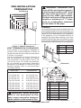
PRE-INSTALLATION PREPARATION
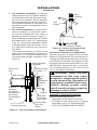
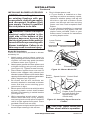
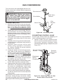
Mantel Depth Mantel From Top of Opening
(1) 14" (A) 16"
(2) 12" (B) 14"
(3) 10" (C) 12"
(4) 8" (D) 10"
(5) 6" (E) 8"
(6) 4" (F) 6"
(7) 2" (G) 4"
CAUTION: Do not block
required air spaces with insula-
tion or any other material. Do not
obstruct the effective opening
of the appliance with any type
of facing material.
CLEARANCES TO COMBUSTIBLES
Minimum clearances to combustibles for the
replace are:
• Back and Sides of Fireplace ........ 0"
• Floor ..........................0"
• Perpendicular Wall ...............6"
• Front ......................... 36"
• Top of Standoffs .................. 0"
6. Have venting system inspected annually
by a qualied service person. If needed,
have venting system cleaned or repaired.
7. Do not use any solid fuels (wood, coal,
paper, cardboard, etc.) in this replace.
Use only the gas type indicated on re-
place nameplate.
8. This appliance, when installed, must be
electrically grounded in accordance with
local codes or, in the absence of local
codes, with the National Electrical Code,
ANSI/NFPA 70.
SAFETY
Continued
9. Do not use replace if any part has been
exposed to or under water. Immediately
call a qualied service person to arrange
for replacement of the unit.
10. Do not operate replace if any log is
broken.
11. Do not operate replace with glass door
removed, cracked or broken.
12. Provide adequate clearances around air
openings.
MANTEL CLEARANCES
Woodwork, such as wood trims, mantles
and other combustible materials should be
placed within the required clearance speci-
ed in Figure 2.

www.fmiproducts.com
125205-01E 7
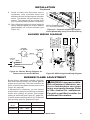
VENT TERMINATION CLEARANCES
Final position of your replace depends on
location of the vent termination in relation to
clearances that must be observed as shown
in Figure 5 on page 8.
The vent system serves as the “chimney” as
well as combustion air supply (air intake).
The horizontal run must have a rise of 1/4"
(0.6 cm) for every 12" (30.48 cm) of horizon-
tal run towards the termination. Maximum
horizontal run depends on vertical rise from
replace adapter collar to vent termination
(see table below).
VERTICAL HORIZONTAL
0 to 1 ft (30.48 cm)
1 ft (30.48 cm) to 4 ft (121.92 cm)
2 ft (60.96 cm) to 8 ft (243.84 cm)
3 ft (91.44 cm) to 12 ft (365.76 cm)
4 ft (121.92 cm) to 16 ft (487.68 cm)
5 ft (152.40 cm) to 15 ft (457.20 cm)
6 ft (182.88 cm) to 14 ft (426.72 cm)
7 ft (213.36 cm) to 13 ft (396.24 cm)
8 ft (243.84 cm) to 12 ft (365.76 cm)
WARNING: Never allow the
vent to run downward as this
may cause excessive tempera-
tures which could cause a re.
PRE-INSTALLATION
PREPARATION
Continued
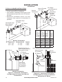
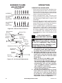
Figure 3 - Framing Dimension
Figure 4 - Corner Installation
A
B
E
F
G
H
D
C
Nailing Tabs
WARNING: Horizontal sec-
tions of this vent system require
a minimum clearance of 2" from
the top of the pipe and 1" mini-
mum to the sides and bottom.
Vertical sections of this system
require a minimum of 1" clear-
ance to combustible materials
on all sides of the pipe.
FRAMING
Once the nal location has been determined, ob-
serving height clearances for vent termination, you
may construct framing using dimensions shown in
Figures 3 and 4, depending on your installation.
If the appliance is to be installed directly on
carpeting, tile (other than ceramic) or any com-
bustible material other than wood ooring, appli-
ance must be installed on a metal or wood panel
extending full width and depth of the appliance.
Figure 2 - Mantel Clearances
C
B
A
D
E
F
G
Top of Louver Opening
3
2
1
4
5
6
7
Wall
B
A
C
CD36M-LS CD42M-LS
A 36
1
/
8
" 40
1
/
8
"
B 41
1
/
4
" 48
1
/
4
"
C 23
1
/
2
" 25
5
/
8
"
CD36M-LS CD42M-LS
A 35
3
/
4
" 41
5
/
8
"
B 15" 21
5
/
8
"
C 49
5
/
8
" 58
1
/
2
"
D 10
3
/
8
" 13
1
/
2
"
E 13
3
/
4
" 16
3
/
4
"
F 41" 48"
G 41
1
/
4
" 48
1
/
4
"
H 68
1
/
2
" 81
1
/
2
"

www.fmiproducts.com
125205-01E8
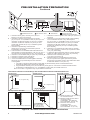
Fixed
Closed
Openable
Fixed
Closed
V
V
V
V
V
V
V
V
X
X
V
X
G
G
J
F
B
B
K
N
H
I
A
N
E
L
D
B
M
A
C
B
V
V
A
G
G
B
TERMINATION CAP
AIR SUPPLY INLET
GAS METERRESTRICTED AREA
(TERMINATION PROHIBITED)
A = clearance above grade, veranda, porch, deck, or
balcony [*12" (30.5 cm) minimum]
B = clearance to window or door that may be opened
[6" (15 cm) min. for 10,000 Btu or less; 9" (23 cm) in US
if between 10,000 and 50,000, 12" (30 cm) in Canada
if between 10,000 and 100,000; 12" (30 cm) in US if
greater than 50,000, 36" (91 cm) in Canada if greater
than 100,000]
C = clearance to permanently closed window
[minimum 12" (30.5 cm) recommended to prevent
condensation on window]
D = vertical clearance to ventilated soffit located above the
terminal within a horizontal distance of 24" (61 cm) from
the center-line of the terminal [18" (45.7 cm) minimum]
E = clearance to unventilated soffit [12" (30.5 cm) minimum]
F = clearance to outside corner (see below)
G = clearance to inside corner (see below)
H = *not to be installed above a meter/regulator assembly
within 36" (91.4 cm) horizontally from the center line
of the regulator
I = clearance to service regulator vent outlet [*72" (182.9 cm)
minimum]
J = clearance to non-mechanical air supply inlet to building
or the combustion air inlet to any other fireplace
[6" (15 cm) min. for 10,000 Btu or less; 9" (23 cm) in US
if between 10,000 and 50,000, 12" (30 cm) in Canada
if between 10,000 and 100,000; 12" (30 cm) in US if
greater than 50,000, 36" (91 cm) in Canada if greater
than 100,000]
K = clearance to a mechanical air supply inlet [*In Canada,
6 ft. (1.83m) minimum; In US 3 ft. (91 cm) above if within
10 ft. (3 m) horizontally]
L = † clearance above paved side-walk or a paved driveway
located on public property [*84" (213.3 cm) minimum]
M = clearance under veranda, porch, deck
[*12" (30.5 cm) minimum ‡]
N = clearance above a roof shall extend a minimum of
24" (61 cm) above the highest point when it passes
through the roof surface and any other obstruction within
a horizontal distance of 18" (45.7 cm)
† vent shall not terminate directly above a side-walk or paved driveway which is located between two
single family dwellings and serves both dwellings*
‡ only permitted if veranda, porch, deck or balconey is fully open on a minimum of 2 sides beneath the floor*
* as specified in CAN/CSA B149 (.1 or .2) Installation Codes (1991) for Canada and U.S.A.
Note: Local codes or regulations may require different clearances
A = 6" (15.2 cm)
Inside Corner
V
B
E
V
B = 6" (15.2 cm)
C = Maximum depth of 48" (121.9 cm)
for recessed location
D = Minimum width for back wall of
recessed location -
Combustible - 38" (965 mm)
Noncombustible - 24" (61 cm)
E = Clearance from corner in
recessed location-
Combustible - 6" (15.2 cm)
Noncombustible - 2" (5.1 cm)
Outside Corner Recessed Location
G
H
G = 12" (30.5 cm) minimum clearance
Balcony with No Side Wall
V
J
Combustible &
Noncombustible
H = 24" (61 cm)
J = 20" (50.8 cm)
Balcony with Perpendicular Side Wall
C
D
C
Termination Clearances for Buildings with Combustible and Noncombustible Exteriors
Openable
Figure 5 - Minimum Clearances for Vent Terminations
PRE-INSTALLATION PREPARATION
Continued

www.fmiproducts.com
125205-01E 9
REQUIREMENTS FOR THE COMMONWEALTH OF
MASSACHUSETTS
For all side wall horizontally vented gas fueled
equipment installed in every dwelling, building or
structure used in whole or in part for residential
purposes, including those owned or operated by
the Commonwealth and where the side wall ex-
haust vent termination is less than seven (7) feet
above nished grade in the area of the venting,
including but not limited to decks and porches,
the following requirements shall be satised:
INSTALLATION OF CARBON
MONOXIDE DETECTORS
At the time of installation of the side wall horizon-
tal vented gas fueled equipment, the installing
plumber or gas tter shall observe that a hard
wired carbon monoxide detector with an alarm
and battery backup is installed on the oor level
where the gas equipment is to be installed. In
addition, the installing plumber or gas tter shall
observe that a battery operated or hard wired car-
bon monoxide detector with an alarm is installed
on each additional level of the dwelling, building or
structure served by the side wall horizontal vented
gas fueled equipment. It shall be the responsibility
of the property owner to secure the services of
qualied licensed professionals for the installation
of hard wired carbon monoxide detectors.
In the event that the side wall horizontally
vented gas fueled equipment is installed
in a crawl space or an attic, the hard wired
carbon monoxide detector with alarm and
battery back-up may be installed on the next
adjacent oor level.
In the event that the requirements of this
subdivision can not be met at the time of
completion of installation, the owner shall
have a period of thirty (30) days to comply with
the above requirements; provided, however,
that during said thirty (30) day period, a battery
operated carbon monoxide detector with an
alarm shall be installed.
Approved Carbon Monoxide Detectors
Each carbon monoxide detector as required
in accordance with the above provisions shall
comply with NFPA 720 and be ANSI/UL 2034
listed and IAS certied.
SIGNAGE
A metal or plastic identication plate shall be
permanently mounted to the exterior of the
building at a minimum height of eight (8) feet
above grade directly in line with the exhaust
vent terminal for the horizontally vented gas
fueled heating appliance or equipment. The
sign shall read, in print size no less than 1/2" in
size, "GAS VENT DIRECTLY BELOW. KEEP
CLEAR OF ALL OBSTRUCTIONS".
INSPECTION
The state or local gas inspector of the side
wall horizontally vented gas fueled equipment
shall not approve the installation unless, upon
inspection, the inspector observes carbon
monoxide detectors and signage installed in
accordance with the provisions of 248 CMR
5.08(2)(a) 1 through 4.
EXEMPTIONS: The following equipment is
exempt from 248 CMR 5.08(2)(a) 1 through 4:
• The equipment listed in Chapter 10 entitled
"Equipment Not Required To Be Vented"
in the most current edition of NFPA 54 as
adopted by the Board; and
• Product Approved side wall horizontally
vented gas fueled equipment installed in a
room or structure separate from the dwell-
ing, building or structure used in whole or
in part for residential purposes.
MANUFACTURER REQUIREMENTS
Gas Equipment Venting System Provided
When the manufacturer of Product Approved
side wall horizontally vented gas equipment
provides a venting system design or venting
system components with the equipment, the
instructions provided by the manufacturer for
installation of the equipment and the venting
system shall include:
• Detailed instructions for the installation of
the venting system design or the venting
system components; and
• A complete parts list for the venting system
design or venting system.
Gas Equipment Venting System Not
Provided
When the manufacturer of a Product Ap-
proved side wall horizontally vented gas fu-
eled equipment does not provide the parts for
venting the ue gases, but identies "special
venting systems", the following requirements
shall be satised by the manufacturer:
•
The referenced "special venting system" in-
structions shall be included with the appliance
or equipment installation instructions; and
• The "special venting systems" shall be Prod-
uct Approved by the Board, and the instruc-
tions for that system shall include a parts list
and detailed installation instructions.
A copy of all installation instructions for all
Product Approved side wall horizontally
vented gas fueled equipment, all venting in-
structions, all parts lists for venting instruc-
tions, and/or all venting design instructions
shall remain with the appliance or equipment
at the completion of the installation.

www.fmiproducts.com
125205-01E10
INSTALLATION
WARNING: This gas replace
and vent assembly must be
vented directly to the outside. The
venting system must NEVER be
attached to a chimney serving a
separate solid fuel burning appli-
ance. Each gas appliance must
use a separate vent system. Do
not use common vent systems.
WARNING: Horizontal sec-
tions of this vent system require
a minimum clearance of 2" from
the top of the pipe and 1" mini-
mum to the sides and bottom.
Vertical sections of this system
require a minimum of 1" clear-
ance to combustible materials
on all sides of the pipe.
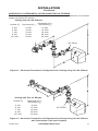
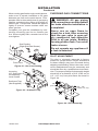
VENTING INSTALLATION
1. Install elbow to replace collar adapter
located on back of the unit at a 45° angle.
Slide elbow over collar and twist to lock.
Check to insure proper connection (see
Figure 6).
2. Continue to install remainder of pipe for
desired installation. Make sure each sec-
tion is twist-locked securely.
3. When installation of vent pipe is complete,
in stall vent termination. Depending on
location of your replace, you will vent
vertically or horizontally.
4. Allow 1" of pipe to protrude from internal
wall, depending on wall thickness. See
Figure 7, page 11.
Figure 6 - Venting Installation
Female
Locking
Lugs
Male
Locking Lugs
Vertical Flue
Restrictor
(For Vertical
Venting
Application)
WARNING: Read all instruc-
tions completely and thoroughly
before attempting installation.
Failure to do so could result in
serious injury, property dam-
age or loss of life. Operation of
improperly installed and main-
tained venting system could
result in serious injury, property
damage or loss of life.
NOTICE: Failure to follow these in-
structions will void the warranty.
VENTING INSTALLATION
PRECAUTIONS
Consult local building codes before beginning
installation. Installer must make sure to select
proper vent system for installation. Before
installing vent kit, installer must read this re-
place manual and vent kit instructions.
Only a qualied service person should install
venting system. The installer must follow
these safety rules:
• Wear gloves and safety glasses for
protection
• Use extreme caution when using ladders
or when on roof tops
• Be aware of electrical wiring locations in
walls and ceilings
The following actions will void the warranty
on your venting system:
• Installation of any damaged venting compo-
nent
• Unauthorized modification of the venting
system
• Installation of any component part not
manufactured or approved for use with the
replace.
• Installation other than as instructed by
these instructions
NOTICE: All FMI PRODUCTS,
LLC direct vent replaces only
approved 5/8" pipe components
and terminations.

www.fmiproducts.com
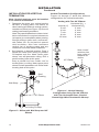
125205-01E 11
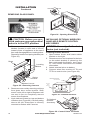
Figure 7 - Vent Termination (Horizontal)
Direct vent
Pipe
Wall Firestop
Maintain 1"
Minimum
Air Space
Around Outer
Pipe when
Penetrating a
Wall
Horizontal
Termination
(Vent Cap)
Screws
Exterior Wall
with Vinyl
Siding
Deector
Shield
Minimum Pipe
Overlap 1
1
/
4
"
Siding Standoff
(Optional)
10
3
/
4
" x 10
3
/
4
"
Framed Opening
5. For horizontal installation, an optional
siding standoff may be installed between
vent cap and exterior wall. Secure horizon-
tal vent cap to standoff. Secure standoff/
vent cap assembly to wall (see Figure 7).
Do not seal termination to vent pipe. Vent
termination must be removable for service
pipe inspection.
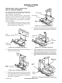
6. For vertical installation, a vertical termi-
nation is available. A vertical ue restric-
tor must be installed into inner collar of
replace as shown in Figure 6, page 10.
When installing a length of pipe for vertical
termination that is over 3 ft., support pipe
every 3 ft. using metal wall straps. Vertical
to horizontal pipe must be kept at a 1 ft. to
4 ft. ratio with a maximum run of no more
than 20 ft.
If an offset is necessary in attic to avoid
obstruction, it is important to support vent
pipe every 3 ft. to avoid excessive stress
on elbows and possible separation (see
Figure 8).
INSTALLATION
Continued
Figure 8 - Vertical Termination with
Offset and Wall Strap
Wall
Strap
Roof
Flashing
45° Elbows
Ceiling Firestop
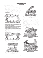
Horizontal Termination Congurations
Figures 9 through 13, pages 12 and 13 show
different congurations and alternatives for
venting with horizontal termination. Each g-
ure includes a chart with critical minimum and
maximum dimensions which MUST be met.
IMPORTANT: Remember that a horizontal
run of venting must have a 1/4" rise for every
12" of run toward termination.
WARNING: Never run vent
downward as this may cause
excessive temperatures which
could cause a re. Operation of
improperly installed and main-
tained venting system could
result in serious injury, property
damage or loss of life.
GROUND FLOOR INSTALLATION
Recommended Applications:
• Installation using cabinet surrounds
• Through the wall using round or square
termination (up to 12" horizontal pipe)
• NOT FOR CORNER INSTALLATION

www.fmiproducts.com
125205-01E12
Vertical (V) Horizontal (H) Series
32
3
/
4
" min. 17" max. CD36
36
3
/
4
" min. 17" max. CD42
Horizontal High
Wind Square
Termination
Wall
Firestop
45° Elbow
Adjustable Pipe
12" Max.
Square Termination
INSTALLATION
Continued
Figure 9 - Horizontal Termination
Conguration for Square and Round
Terminations
45° Elbow
Wall
Firestop
Round
Termination
Cap
Exterior Portion of
Wall Firestop (Round
Termination Only)
Round Termination
Slide Ring
Over Elbow
to Complete
Connection
Figure 10 - Horizontal Termination
Conguration for Corner Installation
Using One 90° Elbow
Square
Termination
Wall
Firestop
Not to Exceed
(H) Limits
As Required
for (V)
See Chart
for Pipe
Section
Required
45°
Elbow
90° Elbow
90° Elbow
Square
Termination
Wall
Firestop
45° Elbow
12"
Minimum
*Note: Ground Floor Corner Venting
Not to Exceed
(H) Limits
TYPICAL CORNER INSTALLATION
Recommended Applications:
• Corner ground oor installation
• Ground oor installation where pipe vents
horizontally through wall (over 12" horizon-
tal pipe)
• Basement installation where one foot
clearance from ground to termination is
possible
CD36 Series
Vertical (V)
Minimum
CD42 Series
Vertical (V)
Minimum
Required
Vertical Pipe
Horizontal (H)
Maximum
*43
1
/
2
" *46
1
/
4
" None 30"
54
1
/
2
" 57
1
/
4
" 1 ft. 48"
66
1
/
2
" 69
1
/
4
" 2 ft. 60"
78
1
/
2
" 81
1
/
4
" 3 ft. 84"
90
1
/
2
" 93
1
/
4
" 4 ft. 20'

www.fmiproducts.com
125205-01E 13
INSTALLATION
Continued
Vertical (V) Horizontal (H
1
)
Horizontal (H
1
) +
Horizontal (H
2
)
5' min. 2' max. 6' max.
6' min. 4' max. 12' max.
7' min. 6' max. 18' max.
8' min. 8' max. 20' max.
20' max. 8' max. 20' max.
45° Elbow
HORIZONTAL SYSTEM INSTALLATION USING TWO 90° ELBOWS
The following congurations show the minimum vertical rise requirements for a horizontal
system using two 90° elbows.
Venting with Two 90° Elbows
Figure 12 - Horizontal Termination Conguration for Venting Using Two 90° Elbows
with Termination at 90° with Fireplace
45° Elbow
Venting with Two 90° Elbows
Figure 11 - Horizontal Termination Conguration for Venting Using Two 90° Elbows
Vertical (V) Horizontal (H
1
) +
Horizontal (H
2
)
5' min. 6' max.
6' min. 12' max.
7' min. 18' max.
8' min. 20' max.
20' max. 20' max.

www.fmiproducts.com
125205-01E14
INSTALLATION FOR VERTICAL
TERMINATION
Note: Vertical restrictor must be installed
in all vertical installations.
1. Determine the route your vertical venting
will take. If ceiling joists, roof rafters, or
other framing will obstruct venting system,
consider an offset (see Figure 13) to avoid
cutting load bearing members.
Note: Pay special attention to these instal-
lation instructions for required clearances
(air space) to combustibles when passing
through ceilings, walls, roofs, enclosures,
attic rafters, etc. Do not pack air spaces
with insulation. Also note maximum
vertical rise of venting system and any
maximum horizontal offset limitations.
2. Set replace in desired location. Drop a
plumb line down from ceiling to position
of replace exit ue. Mark center point
where vent will penetrate ceiling. Drill a
small locating hole at this point.
Drop a plumb line from inside roof to
locating hole in ceiling. Mark center point
where vent will penetrate roof. Drill a small
locating hole at this point.
Figure 13 - Offset with Wall Strap and 45°
Elbows
45° Elbow
Wall Strap
Roof
Flashing
Ceiling Firestop
INSTALLATION
Continued
Vertical Termination Congurations
Figures 14 through 17 show four different
congurations for vertical termination.
Vertical (V)
Horizontal (H
1
) +
Horizontal (H
2
)
5' min. 2' max.
6' min. 4' max.
7' min. 6' max.
8' min. 8' max.
20' max. 8' max.
Figure 14 - Vertical Venting
Conguration Using Two 90° Elbows
with Two Horizontal Runs (Vertical
Round High Wind Termination Shown)
Note: Install
restrictor into
inner collar of
replace as
shown.
45° Elbow
Venting with Two 90° Elbows

www.fmiproducts.com
125205-01E 15
ELECTRICAL HOOKUP AND
REMOTE RECEIVER DIAGRAM
An outlet box with two receptacles (see Figure
18) has been supplied for your convenience
and is located inside on the lower right side of
the replace.
Figure 18 - Duplex Outlet
Three-prong Plug
Outlet Box
INSTALLATION
Continued
Vertical (V) Horizontal (H)
5' min. 2' max.
6' min. 4' max.
7' min. 6' max.
8' min. 8' max.
20' max. 8' max.
Figure 15 - Vertical Venting Conguration
Using One 90° Elbow (Vertical Round
High Wind Termination Shown)
Note: Install restrictor
into inner collar of
replace as shown.
Vertical
(V
1
)
Horizontal
(H)
5' min. 6' max.
6' min. 12' max.
7' min. 18' max.
8' min. 20' max.
Note: Vertical (V
1
) +
Vertical (V
2
) = 40’ max.
Figure 16 - Vertical Venting Conguration
Using Two 90° Elbows (Vertical Round
High Wind Termination Shown)
Note: Install restrictor
into inner collar of
replace as shown.
45° Elbow
45° Elbow
Venting with Two
90° Elbows
Venting with One 90° Elbow
Vertical Venting
V = 40’ max.
Figure 17 - Vertical Venting Conguration
With No Horizontal Run (Vertical Round
High Wind Termination Shown)
Note: Install restrictor
into inner collar of
replace as shown.
45° Elbow

www.fmiproducts.com
125205-01E16
INSTALLATION
Continued
Figure 19 - Remote Control Receiver
ON
OFF
REMOTE
Remote
Control
Receiver
Convertible
Gas Valve
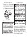
GAS SUPPLY TESTING
NOTICE: This section is in-
tended as a guide for qualied
technicians installing gas to the
appliance.
WARNING: Do not connect
appliance before pressure test-
ing gas piping. Damage to gas
valve may result and an unsafe
condition may be created.
Appliance and its individual shutoff valve
must be disconnected from gas supply piping
system during any pressure testing of that
system at test pressures in excess of 1/2 psig
(3.5 kPa).
Appliance must be isolated from gas supply
piping system by closing its individual shutoff
valve during any pressure testing of gas sup-
ply piping system at test pressures equal to
or less than 1/2 psig (3.5 kPa).
Gas control valve is secured under rebox.
Two 1/8" ports are provided on gas control
valve for pressure test gauge connections
(see Figure 20).
Figure 20 - Gas Control Valve
ON/OFF
Knob
Pilot Adjustment
Inlet
Pressure
Outlet
Pressure
Flame
Adjustment Knob
Pilot Gas Line
Do Not Kink
To Pilot
Burner
To Main
Burner
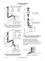
GAS LINE HOOK-UP
WARNING: Gas line hook-
up should be done by your gas
supplier or a qualied service
person.
WARNING: Before you pro-
ceed, make sure your gas supply
is OFF.
An equipment shutoff valve has been included
in replace's gas supply system. Consider
installing an extra shutoff valve outside appli-
ance’s enclosure (check local codes), where it
can be accessed more conveniently with a key
through a wall as shown in Figure 21.
In conformance with local codes, route a 1/2"
NPT gas line towards appliance coming in
from bottom, left or right side of replace (see
Figure 22, page 17).
Install a sediment trap between incoming
gas line and gas control box (see Figure 23,
page 17). The sediment trap should extend
down a minimum of 3" (7.62 cm) beyond
center of pipe.
Figure 21- Typical Exterior Wall Gas
Shutoff Installation
Key
Extension
Shutoff
Valve
The remote control receiver is factory wired
and connected to the convertible gas valve
as shown in Figure 19.

www.fmiproducts.com
125205-01E 17
When routing gas line through conduit sleeve,
make sure to repack insulation to ll gaps
between gas line and conduit sleeve. Com-
pounds used on threaded joints of gas piping
shall be resistant to the action of propane or
natural gas. Compounds should be applied
lightly to ensure excess sealant does not
enter gas line.
Complete your gas line installation by con-
necting incoming gas line to flexible gas
line. Secure tightly with a wrench but do not
over-tighten.
INSTALLATION
Continued
Figure 22 - Gas Line Routing
Gas Routing
(Right Side Not Shown)
Side of
Fireplace
Front Face
Figure 23 - Sediment Trap
Sediment Trap
(Not Supplied)
Incoming
1/2" Gas Line
Permitted By
Local Codes
3" Min.
(7.6 cm)
PILOT ADJUSTMENT
The pilot or electrode assembly is factory
preset for proper ame height. Alterations
to these settings may have occurred during
shipping and handling. If this is the case, some
minor readjustments may be necessary and
should be done by a qualied service techni-
cian. The proper settings for thermopile height
should be at a distance of 3/8" (0.95 cm) to
1/2" (1.27 cm) from pilot ame as shown in
Figure 24.
Figure 24 - Pilot Assembly
1/8"
(0.3 cm)
3/8" - 1/2"
(.95cm-1.3 cm)
CHECKING GAS CONNECTIONS
WARNING: All gas piping
and connections must be tested
for leaks after the installation is
completed.
Never use an open ame to
check for a leak. After ensuring
that the gas valve is open ap-
ply commercial leak detection
uid to all gas joints. Bubbles
forming show a leak. Correct all
leaks at once.
Do not operate any appliance if
a leak is detected.

www.fmiproducts.com
125205-01E18
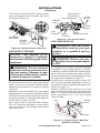
Figure 26 - Opening Glass Door
INSTALLATION
Continued
2. Remove screen rod by removing rod loop
from glass door center bracket. Slide
screen rod to left or right of replace until
one end is free to completely remove
screen from replace.
3. Undo latches located on top and bottom
of rebox (see Figure 26). Carefully swing
door to the left. Glass door is securely
mounted to rebox with 5 screws.
INSTALLING OPTIONAL WIRELESS
HAND-HELD REMOTE CONTROL
MRC SERIES
NOTICE: Use only alkaline bat-
teries (not included).
Installing Remote Receiver
1. Open bottom louver and locate switch
bracket on the right.
2. Remote receiver can be placed in the hole
on the switch bracket or placed on the
oor underneath the rebox, see Figure
27. See remote instructions for further
information.
3. Attach terminal wires to battery.
4. Connect wires from receiver to TH and
TPTH to control valve (see Figure 28).
Figure 27 - Remote Receiver
Figure 28 - Control Valve Terminals
To Optional
Remote
Accessory
To Wall
Thermostat
Wire terminals
Remote Receiver
Receiver
Slide
Button
REMOTE
OFF
ON
LEARN
ADJ.
CAUTION: Before you pro-
ceed, make sure your gas control
valve is in the OFF position.
1. To remove louvers, pull both spring
latches (located in each end of louver)
toward center of appliance at the same
time until disengaged from locating holes.
Repeat for bottom end spring latches (see
Figure 25).
Figure 25 - Removing Louvers
Glass
Locating
Holes
Spring
Latch
Bottom Louver
REMOVING GLASS PANEL
Glass Door
Lock
Unlock

www.fmiproducts.com
125205-01E 19
INSTALLATION
Continued
INSTALLING LOGS, LAVA ROCK
AND GLOWING EMBERS
It is very important to install these logs exactly
as instructed. Do not modify logs. Only use
logs supplied with replace.
Open louvers, remove screen, unlock door
latches, and open glass door. See Removing
Glass Panel, steps 1 to 3, page 18. Install
logs according to instructions for replace
model numbers.
1. Find and place log #1 (rear log) on top of
grate. Make sure notches in bottom of log
t over grate (see Figure 29).
Figure 29 - Installing Log No. 1
Figure 30 - Installing Log No. 2
3. Place log #3 (crossover log) onto rear and
front logs. Make sure it is seated properly
on surface of rear log and pin on front log
as shown in Figure 31.
2. Rest log #2 (front log) on pins on front part
of grate (see Figure 30).
Figure 31 - Installing Log No. 3
Figure 32 - Installing Log No. 4
5. Place log #5 (base log) onto front left part of
grate making sure notch and hole t over
metal pin and prong of grate. See Figure 33.
6. Place log #6 (left log) onto rear log landing
and resting it on top of front log. See Figure
33.
Figure 33 - Installing Logs No. 5 and No. 6
1
2
3
4
Metal
Pins
Metal
Pin
Rear Log
Front Log
Crossover
Log
Log
Landing
Front
Log
Log
Notches
Grate
Assembly
5
6
Metal
Pin
Grate
Prong
Rear Log
Landing
4. Place log #4 (right log) onto log landing on
right side of front log as shown in Figure 32.

www.fmiproducts.com
125205-01E20
Model CD42M-LS Series
1. Place log #1 (small base log) onto pin
on left side of grate extension (see
Figure 34).
2. Rest left side of log #2 (front log) on top
of log #1 and right side onto pin located
on right side of grate extension (see
Figure 35).
INSTALLATION
Continued
Figure 34 - Installing Log #1, Model
CD42M-LS
Figure 35 - Installing Log #2, Model
CD42M-LS
Figure 36 - Installing Log #3, Model
CD42M-LS
1
1
2
3
Figure 37 - Installing Log #4, Model
CD42M-LS
Figure 38 - Installing Log #5, Model
CD42M-LS
Figure 39 - Installing Logs #6 and #7,
Model CD42M-LS
5
6
7
4
3. Place log #3 (rear log) onto pins on rear
of grate (see Figure 36).
4. Place log #4 (crossover log) onto pins from
both logs #2 and #3 (see Figure 37).
5. Place log #5 (top log) onto right pin of front
log (#2) and smooth surface of rear log
(#3). Make sure it is seated properly (see
Figure 38).
6. Place log #6 (left log) on left pin of front
log (#2) and smooth surface of rear log
(#3). Make sure it is seated properly (see
Figure 39*).
7. Place log #7 (right log) on right pin of top
log (#5). Make sure it is seated properly
(see Figure 39).
Page is loading ...
Page is loading ...
Page is loading ...
Page is loading ...
Page is loading ...
Page is loading ...
Page is loading ...
Page is loading ...
Page is loading ...
Page is loading ...
Page is loading ...
Page is loading ...
Page is loading ...
Page is loading ...
Page is loading ...
Page is loading ...
Page is loading ...
Page is loading ...
Page is loading ...
Page is loading ...
-
 1
1
-
 2
2
-
 3
3
-
 4
4
-
 5
5
-
 6
6
-
 7
7
-
 8
8
-
 9
9
-
 10
10
-
 11
11
-
 12
12
-
 13
13
-
 14
14
-
 15
15
-
 16
16
-
 17
17
-
 18
18
-
 19
19
-
 20
20
-
 21
21
-
 22
22
-
 23
23
-
 24
24
-
 25
25
-
 26
26
-
 27
27
-
 28
28
-
 29
29
-
 30
30
-
 31
31
-
 32
32
-
 33
33
-
 34
34
-
 35
35
-
 36
36
-
 37
37
-
 38
38
-
 39
39
-
 40
40


Ask a question and I''ll find the answer in the document
Finding information in a document is now easier with AI
Related papers
Other documents
-
Montigo M38DV-ST User manual
-
White Mountain Hearth Burner Assembly Kit Owner's manual
-
Astria Fireplaces Odyssey Instruction Sheet
-
Desa CD42M-A User manual
-
-
-
 Archgard Harmonia 22 User manual
-
Sherwood 50-1445 Installation guide
-
-
 Vexar Coleman CD36M-A2 Owner's Operation And Installation Manual

