Page is loading ...

Harmonia 22
Model: 22-DVIM22LN-1
GAS FIRED DIRECT VENT
FIREPLACE INSERT
S/N 230000 AND UP
ARCHGARD FIREPLACE PRODUCTS
7116 Beatty Drive
Mission, BC V2V 6B4 Canada 200-0064-01
August 29, 2023
Installation Manuals available through your local dealer or visit
our website at: www.archgard.com
INSTALLER: LEAVE THIS MANUAL WITH THE APPLIANCE.
CONSUMER: RETAIN THIS MANUAL FOR FUTURE REFERENCE.
This appliance may be installed in an aftermarket
permanently located, manufactured home (USA only) or
mobile home where not prohibited by local codes.
This appliance is only for use with the type of gas indicated
on the rating plate. This appliance is not convertible for use
with other gases, unless a certied kit is used.
INSTALLATION, OPERATION, AND
MAINTENANCE MANUAL
−Do not store or use gasoline or other ammable vapors
or liquids in the vicinity of this or any other appliance.
−WHAT TO DO IF YOU SMELL GAS:
• Do not try to light any appliance.
• Do not touch any electrical switch; do not use any
phone in your building.
• Immediately call your gas supplier from a
neighbor's phone. Follow the gas suppliers
instructions.
• If you can not reach your gas supplier, call the re
department.
−Installation and service must be performed by a
qualied installer, service agency or the gas supplier.
WARNING:
FIRE OR EXPLOSION HAZARD
Failure to follow safety warnings exactly could result in
serious injury, death, or property damage.
SIT 820
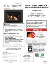
Gas Fireplace Energy Eciency
Rating 63.13%
Based on CSA P.4.1-15
SIT 821
Gas Fireplace Energy Eciency
Rating 66.14%
Based on CSA P.4.1-15

2
TABLE OF CONTENTS
1.0 Introduction 3
2.0 Safety Information 4
3.0 Technical Information 5
3.1 Appliance Certication 5
3.2 Installation Codes 5
3.3 Specications 5
3.4 High Altitude Installation 5
4.0 Rating Plate 6
5.0 Installation Checklist 7
6.0 Appliance Overview 8
6.1 Rating Plate Location 8
6.2 Appliance Overview 8
6.3 Leveling the Appliance 8
6.4 Accessing the Controls 9
6.5 Identifying the Controls 9
7.0 Electrical Connections 10
8.0 Appliance Dimensions 11
9.0 Minimum Opening Dimensions 12
9.1 Surround Conguration Options 13
9.2 Factory Built Fireplaces 15
9.3 Refacing a Masonry Fireplace 16
10.0 Clearances to Combustibles 17
10.1 Mantel Clearances 17
10.2 Sidewall Clearances 18
10.3 Hearth Clearances 18
11.0 Gas Connections 19
11.1 Clocking Procedure 19
12.0 Conversion Kit Instructions 20
12.1 Prepare the Fireplace 20
12.2 Pilot Conversion 20
12.4 Complete the Conversion 21
12.3 Convert the Gas Valve 21
13.0 Venting Instructions 22
13.1 Approved Venting Components 23
13.2 Min/Max Vent Run 25
13.3 Using a Co-linear to Coaxial Adapter 26
14.0 Barrier Screen Installation 27
15.0 Glass Door Installation 28
15.1 If Your Glass Breaks 28
16.0 Surround Installation 29
16.1 Installing the ON/OFF Switch 30
16.2 Bottom Filler Plate 31
16.3 Surround Dimensions 32
17.0 Firebox Liner Installation 35
17.1 Brick Panel Installation 35
17.2 Reective Glass Installation 36
18.0 Media Installation 37
18.1 Log Set 37
19.0 Operation 41
19.1 Before Lighting 41
19.2 First Fire 41
19.3 Lighting Instructions 42
19.4 Lighting The Fireplace 43
20.0 Maintenance 45
20.1 Cleaning and Routine Maintenance 45
20.2 Servicing Under Warranty 46
20.3 Checking Inlet and Outlet Pressure 46
20.4 Checking and Adjusting Pilot 46
20.5 Adjusting the Primary Air 47
20.6 Replacing the Burner 48
20.7 Replacing the Pilot 49
20.8 Replacing the Valve 50
20.9 Replacing the Piezo Igniter 52
20.10 Replacing the Optional Fan 53
20.11 Replacing the Optional Fan Speed
Control 55
20.12 Replacing the Optional Fan Thermal
Sensor 56
20.13 Wiring Schematic 57
20.14 Troubleshooting 58
21.0 Frequently Asked Questions 60
22.0 Replacement Parts List 61
Archgard Limited Warranty 62

3
General Information
1.0 Introduction
Thank You and Congratulations for choosing an Archgard Gas Fireplace insert!
Harmonia (Har-MO-nee-ah) - The immortal goddess of harmony and concord. Harmonia presided over both marital harmony and the
harmonious action of soldiers in war. Harmonia is described as having a heart that is completely pure, without bad thoughts whatsoever.
The Harmonia 22 is among the most advanced Direct Vent Insert heaters available today. It is solidly designed using the latest
technology and manufactured to the highest quality. It is our aim to provide you with an appliance that brings many trouble-free years of
reliable service. This manual provides information regarding model number 22-DVIM22LN-1.
Some of the many features of your 22-DVIM22LN-1 are:
• Heater Classication This replace is classied as a heating appliance. Therefore, it uses Direct Vent safety technology
and it is suitable for continuously operated zone heating.
• High Eciency This replace has one of the highest eciencies of any Direct Vent gas insert, ensuring it is less
expensive to operate.
• Adjustable Fan Speed
(optional)
An adjustable six speed circulation fan is available for this replace insert.
• Adjustable Flame This replace provides the ability to adjust the ame aesthetics and heat output to suit the owner's
liking and heating needs.
• Solid Construction This replace is mainly constructed of 16 and 18 gauge galvanized and aluminized coated steel for
long life and durability.
• Optional Accessories Speak with your local Authorized Archgard Dealer for a full complement of decorative accessories
to suit your home's decor and personal tastes.
• Remote Control
Compatible
You may install a third party remote control providing convenient operation from the comfort of your
chair.
Please complete and submit the warranty registration card included in the back of this manual or by visiting us at:
www.archgard.com/warranty-registration
Model Number Denition (22-DVIM22LN-1)
22 Number assigned to identify this model.
DVI Direct Vent Insert
MMillivolt Ignition
22 Natural Gas Input Rating in BTU
LTraditional Log Burner
NNatural Gas
-1 Revision Number

4
General Information
2.0 Safety Information
Caution
FOR YOUR SAFETY - Do not install or operate this appliance without reading and understanding this manual. Any installation or
operational deviation from this instruction manual voids the warranty and may prove hazardous.
• This appliance must be installed by a qualied gas installer and the installation must conform to the installation codes.
• Provide adequate clearance around air openings into combustion chamber.
• Never obstruct front openings.
• Provide adequate clearances for proper operation and servicing of the appliance.
• This appliance must be properly connected to an approved venting system and must not be connected to a chimney ue serving a
separate solid fuel burning appliance.
• Flow of combustion and ventilation air must not be obstructed.
• Always provide adequate clearance around the intake and exhaust openings.
Safety
• Due to high temperatures, the appliance should be located out of trac and away from furniture and draperies.
• Children and adults should be alerted to the hazards of high surface temperature and stay away to avoid burns or clothing ignition.
• Young children should be carefully supervised when they are in the same room as the appliance. Toddlers, young children and
others may be susceptible to accidental contact burns. A physical barrier is recommended if there are at risk individuals in the
house. To restrict access to a replace or stove, install an adjustable safety gate to keep toddlers, young children and other at risk
individuals out of the room and away from hot surfaces.
• Do not store or place combustibles, gasoline, and other ammable vapors and liquids near the appliance.
• Clothing or other ammable material should not be placed on or near the appliance.
• Do not operate with cracked or broken glass. Do not to strike or slam the glass.
• WARNING: Do not operate appliance with the glass front removed, cracked, or broken. Removal of the glass should be done by a
licensed or qualied service person.
• Any safety screen or guard removed for servicing an appliance must be replaced prior to operating.
• Installation and Repair should be done by a qualied service person. The appliance should be inspected before use and at least
annually by a professional service person. More frequent cleaning may be required due to excessive lint from carpeting, bedding
materials, etc. It is imperative that the control compartments, burners and circulating air passageways of the appliance are kept
clean.
• Do not use this appliance if any part has been under water. Immediately call a qualied service technician to inspect the appliance
and to replace any part of the control system and any gas control which has been under water.
• California Proposition 65 Warning: This product can expose you to chemicals including Carbon Monoxide, that is an externally
vented by-product of fuel combustion, which is [are] known to the State of California to cause cancer, birth defects, or other
reproductive harm. For more information, visit www.P65Warnings.ca.gov.
Each Archgard Gas Fireplace is checked and tested at the factory prior to being packaged and shipped to our dealers and nally
installed in your home. Before leaving this unit with the customer, the installer must ensure that the appliance is ring correctly and that
the electrical system is in working order. The Installation Checklist in Section 5.0 should be used to ensure the proper installation of this
gas replace insert and to document any deviations from a typical install.
Any alteration to the product that causes carbon or soot deposits that results in any damage or requires
cleaning is not the responsibility of the manufacturer.

5
General Information
3.0 Technical Information
3.1 Appliance Certication
This appliance was listed by QAI Laboratory Inc to the following USA and Canadian gas appliance standards.
- ANSI Z21.88-2019 / CSA 2.33-2019 Vented Gas Fireplace Heaters
- CSA-2.17-2017, Gas-Fired Appliances for Use at High Altitudes
- CSA P.4.1-15 testing method for measuring annual replace eciency
- CSA 22.2 No.3-M1988(R2014) electrical standard
The listing label is attached to the appliance on the bottom right side of the appliance.
A copy is shown on Section 4.0.
Commonwealth of Massachusetts: This appliance has been manufactured in accordance with Massachusetts code 248 CMR 5.00.
Approval Code: TBD. (http://license.reg.state.ma.us/public/licque.asp).
Please contact Archgard Industries Ltd., if you have any questions regarding the certication of this appliance.
3.2 Installation Codes
This appliance must be installed by a qualied gas appliance installer. The installation must conform with the local codes or, in
the absence of local codes, with the current National Fuel Gas Code ANSI Z223.1/ NFPA 54 in the US, or Installation Code CAN/
CGA-B149.1 in Canada. Electrical connections and grounding must conform with local code, or current National Electrical code ANSI/
NFPA No. 70-1987 in the US, and in Canada the current Canadian Electrical Code CSA C22.1.
This appliance is certied for installation in a bedroom or a bed sitting room. Please refer to local codes for thermostat requirements.
We recommend that our gas hearth products be installed and serviced by professionals who are certied in the U.S. by the
National Fireplace Institute® (NFI) as NFI Gas Specialists.
3.3 Specications
Natural Gas (NG) Propane (LP)
Manifold Pressure 1.6 - 3.5 in. W.C. (0.4 - 0.9 kPa) 6.4 - 10.0 in. W.C. (1.6 - 2.5 kPa)
Min. Supply Pressure
Max Supply Pressure 5.0 in. W.C. (1.24 kPa)
14.0 in. W.C. (3.5 kPa)
11.0 in. W.C. (2.7 kPa)
14.0 in. W.C. (3.5 kPa)
Orice Size #44 DMS (2.18 mm dia) #54 DMS (1.397 mm dia)
Input Rating 15,000 - 22,000 BTU/hr (4.4- 6.45 kW) 17,000 - 22,000 BTU/hr (4.98 -6.45 kW)
P.4 Fireplace Eciency (FE) SIT 820: 63.13%
SIT 821: 66.14%
P.4 Steady State Eciency SIT 820: 70.01%
SIT 821: 70.01%
Electrical Rating 120 VAC, 60Hz less than 2 A.
Gas Control SIT 820 or SIT 821
Altitude 0 - 4,500 ft. (0 - 1372 M)
Primary Air Opening 1/4” (6.35 mm) OPEN 1/4” (6.35 mm) OPEN
3.4 High Altitude Installation
When installing this appliance beyond 4500 ft. (1372 M) above sea level, the appliance must be properly derated and installed
according to local codes, in the absence of local codes, with the current National Fuel Gas Code, ANSI Z223.1/ NFPA 54, in the US or
Installation Code, CAN/CGA-B149.1, in Canada.

6
General Information
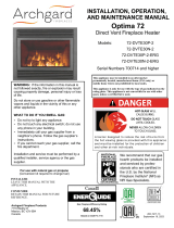
4.0 Rating Plate
SAMPLE
MODEL: 22-DVIM22LN-1
DO NOT REMOVE THIS LABEL
LISTED VENTED GAS FIREPLACE HEATER and GAS-FIRED APPLIANCES FOR USE AT HIGH ALTITUDES. Tested to: ANSI
Z21.88-2019 / CSA 2.33-2019, CSA 2.17-2017, CSA P.4.1-15, and CSA 22.2 No.3-M1988 (R2014). This vented gas replace heater
is not for use with air lters. Certied for use in both CANADA and USA.
VENTED GAS FIREPLACE HEATER-NOT FOR USE WITH SOLID FUEL.
Manufactured as Natural Gas
NG LPG
Input rating 15,000 - 22,000 BTU/hr
(4.4 - 6.45 kW) 17,000 - 22,000 BTU/hr
(4.98 - 6.45 kW)
Manifold Pressure 1.6 - 3.5 in. W.C. (0.4 - 0.9 kPa) 6.4 - 10.0 in. W.C. (1.6 - 2.5 kPa)
Orice size #44 DMS (2.18 mm dia.) #54 DMS (1.397 mm dia.)
Supply pressure (Min - Max) 5.0 - 14.0 in. W.C.
(1.2 - 3.5 kPa) 11.0 - 14.0 in. W.C.
(2.7 - 3.5 kPa)
Burner Primary Air Setting 1/4” (6.35mm) Open 1/4” (6.35mm) Open
Altitude 0 - 4500 ft (0 - 1372 m) 0 - 4500 ft (0 - 1372 m)
Electrical rating 120 VAC, 60 Hz less than 2 A.
Replacement fan Optional fan kit available
Keep burner and control compartment clean. See
Instructions accompanying the heater.
Optional fuel conversion kit : See Manual
Minimum opening Dimensions:
23.9”(60.7 cm)W x 17.98”(45.7 cm)H x 16.125”(40.96 cm)D
Minimum Chimney Flue Size:4” (100 mm) x 7” (176 mm)
Minimum clearances to Combustibles:
Sides from glass door frame: 7” (17.8 cm)
Mantle: max 8” (20.3 cm) at min 15” (38.1 mm)
from top of appliance door
See Manual for additional dimensions and clearances
This appliance must be installed in accordance with local codes, if any; if none, follow the National Fuel Gas Code, ANSI
Z223.1/NFPA 54, or Natural Gas and Propane Installation Codes, CSA B149.1. Electrical connections and grounding must
be in accordance with local codes, if any; if none, follow the current CAN/CSA C22.1 in Canada and ANSI/NFPA 70 in the
US. This appliance is certied for installation in a bedroom or a bed sitting room. This appliance is only for use with the gas
indicated on the rating plate and may be installed in an aftermarket, permanently located, manufactured (mobile) home where
not prohibited by local codes. See owner’s manual for details. This appliance is not convertible with other gases, unless a
certied kit is used.
WARNING: Improper installation, adjustment, alteration, service, or maintenance can cause injury or property damage. Refer
to the owner’s information manual provided with this appliance. For assistance or additional information consult a
qualied installer, service agency, or the gas supplier. This appliance must be properly connected to a Direct Vent
venting system in accordance with the manufacturer’s installation instructions.
WARNING: Failure to install this appliance per the manufacturer’s instructions or failure to use only parts specically
approved with this appliance may result in property damage or personal injury.
WARNING: Do not operate the appliance until all sections have been assembled and installed in accordance with the
manufacturer’s instructions.
WARNING: Operation of this appliance when not connected to a properly installed and maintained venting system can result
in carbon monoxide (CO) poisoning and possible death.
ONLY DOORS CERTIFIED WITH THE APPLIANCE SHALL BE USED.
For use only with barrier part # 22-BS. Follow installation instructions.
Made in Canada by:
Archgard Industries Ltd.
7116 Beatty Dr., Mission, B.C.
August 2021 303-6022-01
MANUFACTURE DATE:
Gas Control: SIT 820
Continuous Pilot
SIT 821
7 Day Pilot On Demand Timer
P.4.1 Fireplace Eciency (FE): 63.13% 66.14%

7
Installation
5.0 Installation Checklist
This standard installation checklist is to be used by the installer in conjunction with, not instead of, the instructions contained
within this installation manual.
Customer: Date Installed:
Install Address: Location of Fireplace:
Installer:
Solid Fuel Zero Clearance Install: (Section 9.2) YES NO IF NO, WHY NOT?
Was the bottom of the existing zero clearance rebox removed?
Was a 0.15" (3.8 mm) minimum clearance maintained as shown in
Figure 9.2.02?
Venting: (Section 13.0) YES NO IF NO, WHY NOT?
Venting conguration complies with vent diagrams.
Venting installed, fastened, and secured in place maintaining proper
clearances.
Secured or removed existing solid fuel replace damper.
Terminations installed and sealed in compliance with local building
code.
Direct vent termination is highest point in vent assembly.
Wiring / Electrical: (Section 7.0) YES NO IF NO, WHY NOT?
Connected to household 110/120v per local codes.
Unit is properly grounded.
Gas: (Section 11.0) YES NO IF NO, WHY NOT?
Proper appliance for fuel type?
Was a conversion performed?
Leak check performed & inlet and manifold pressures veried?
Was the rating of the insert clocked?
Finishing: YES NO IF NO, WHY NOT?
Only noncombustible material installed in noncombustible areas.
Clearances meet installation manual requirements.
Mantels and/or projections comply with install manual.
Was the solid fuel replace warning plate installed (Figure 9.0.02)?
Appliance Setup: YES NO IF NO, WHY NOT?
Log set, door, and screen installed according to install manual.
Manual given to home owner.
Did you check operation of the fan (if installed) and ame modulation?
Does the main burner light within 4 seconds of main gas valve
opening (see Section 20.1)?

8
Installation
6.0 Appliance Overview
6.1 Rating Plate Location
Figure 6.1.01:
6.2 Appliance Overview
The valve and control module are located
underneath the replace. They can be accessed
by ipping down the control access cover on the
replace surround.
The optional fan is located on the inside of the rear
replace shell and can only be accessed from the
rear of the replace.
Note: This manual may use images of an unpainted
replace for the purposes of illustration.
*Left and right side references in this manual
correspond with the sides identied in Figure
6.2.01.
6.3 Leveling the Appliance
The 22-DVIM22LN-1 is equipped with front and rear leveling bolts.
The replace has the ability to independently level left/right and
front/back.
Leveling is done from the bottom of the unit
Figure 6.2.01:
Figure 6.3.01:
The rating plate is located under the rebox, behind the control access cover. See Section 6.4 for information on accessing the
controls.
Front Bolts
Rear Bolts
Surround
Left Side Right Side
Control Access Cover
Rating Plate Location

9
Installation
6.4 Accessing the Controls
The controls for the 22-DVIM22LN-1 are located underneath the
replace and are accessed by ipping down the control access
cover shown in Figure 6.4.01.
Figure 6.4.01:
6.5 Identifying the Controls
See Figure 6.5.01 for Identication of the controls. See Operation Section 19.0 for operation instructions.
Figure 6.5.01
Gas Shut-o
Valve
Valve
Optional Fan
Speed Control
Piezo
Ignighter
Optional
Fan

10
Installation
7.0 Electrical Connections
The 22-DVIM22LN-1 may be wired to a thermostat, wall switch, or third party remote control. An optional variable 6 speed fan kit is
available from your local authorized Archgard dealer. Do not cut or remove the grounding prong from the main power supply plug on the
optional fan kit.
CAUTION: Label all wires prior to disconnection when servicing.
NOTE: This appliance, when installed, must be electrically grounded in accordance with local codes or, in the absence of local codes,
with the National Electrical Code, ANSI / NFPA 70, or the Canadian Electrical code, CSA C22.1.
Before you begin:
• Flip Down the Control access cover (See Section 6.4)
To connect a thermostat or wall switch to the replace:
Step 1: Remove the shielding from the ends of the household
wiring. See Figure 7.0.02 for recommended wire specications.
Thermostat / wall switch wire table
Recommended Maximum Lead Length for two wires.
Wire Size Max. Length
14 GA. 50 Ft. (15.24 M)
16 GA. 32 Ft. (9.75 M)
18 GA. 20 Ft. (6.9 M)
20 GA. 12 Ft. (3.65 M)
22 GA. 9 Ft. (2.74 M)
Figure 7.0.01: Figure 7.0.02:
Step 2: Run the wire through the opening on either side of the
replace. Always keep the wire low, away from the rebox.
Figure 7.0.03:
Step 3: Connect the wire to the leads on the valve.
Figure 7.0.04:
Note: See Figure 20.13.01 for a wiring diagram including the wall
switch or optional thermostat.
Note: Wall switches, thermostats, or remote controls are not
included with the replace and are not covered under warranty.

11
Installation
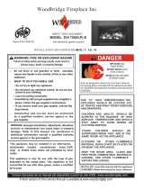
8.0 Appliance Dimensions
Top View
Front View
Side View
Figure 8.0.01:
22.923in
25.291in
1.423in
16.885in
3.000in
17.976in
13.485in
12.995in
15.885in 16.885in
10.518in
23.000in
12.765in
25.485in

12
Installation
9.0 Minimum Opening Dimensions
The installer must mechanically attach the marking supplied with the gas replace insert to the inside of the rebox of the replace into
which the gas replace insert is installed. See Figure 9.0.02.
Cutting of any sheet-metal parts of the replace, in which the gas replace insert is to be installed, is prohibited except as described in
Section 9.2.
The replace and replace chimney must be clean and in good working order and constructed of noncombustible materials. The
chimney clean-outs must t properly.
WARNING: This replace has been converted for use with a gas replace insert only and cannot be used
for burning wood or solid fuels, unless all original parts have been replaced, and the replace
reapproved by the authority having jurisdiction.
AVERTISSEMENT: Ce foyer a ete converti pour utilisation avec un foyer au gaz encastrable et ne peut etre utiliser
pour bruler du bois ou autres combustibles solides a moins que toutes les pieces d'origine ete
remplacees et que le foyer ait ete approuve de nouveau par l'autorite competente.
303-0123
Figure 9.0.02:
Figure 9.0.01:
WARNING: Failure to position the parts in accordance with these diagrams or failure to use only parts specically approved with this
appliance may result in property damage or personal injury.
The following opening dimensions show the absolute minimum opening size allowable for the 22-DVIM22LN-1. This appliance may be
congured to accommodate a variety of openings and aesthetic preferences.
Depending on the conguration of the surround, the minimum opening dimensions may change. Refer to Section 9.1 for installation
options.
SIDE VIEW
TOP VIEW
Min ue size required 4" (10.2 cm) x 7" (17.8 cm) unless
reducer kit 22-LKF2 is used*. See Section 13.3.

13
Installation
9.1 Surround Conguration Options
The surround may be adjusted to accommodate a variety of openings and aesthetic preferences.
The following table indicates opening dimensions required for each possible position of the surround. The dimensions indicated in the
images below correspond with the locations shown in Figure 9.0.01.
Position 1 Position 2 Position 3
A
B
C
A
B
C
A
B
C
Minimum Depth
Door Flush
Screen Flush
A
B
C
A
B
C
A
B
C
Minimum Depth
Door Flush
Screen Flush
A
B
C
A
B
C
A
B
C
Minimum Depth
Door Flush
Screen Flush
E
F
D
G
E
F
D
G
E
F
D
G
Minimum Depth
Screen Flush
Door Flush
E
F
D
G
E
F
D
G
E
F
D
G
Minimum Depth
Screen Flush
Door Flush
E
F
D
G
E
F
D
G
E
F
D
G
Minimum Depth
Screen Flush
Door Flush
Minimum Depth:
The screen and door both extend
outside of the surround.
Door Flush:
The screen extends outside of the
surround but the face of the door does
not.
Screen Flush:
The face of screen is ush with the
surround.
A18.0" (45.72 cm) 18.0" (45.72 cm) 18.0" (45.72 cm)
B12.94" (32.87 cm) 13.41" (34.06 cm) 14.10" (35.81 cm)
C3.76" (9.55 cm) 4.22" (10.72 cm) 4.91" (12.47 cm)
D14.17" (35.99 cm) 12.48" (31.70 cm) 12.48" (31.70 cm)
E16.13" (40.97 cm) 16.62" (42.21 cm) 17.31" (43.97 cm)
F23.91" (60.73 cm) 25.92" (65.83 cm) 26.48" (67.26 cm)
G106.75⁰112⁰112⁰
Figure 9.1.01:
Caution: if installing at minimum depth, the rigid black pipe included with this replace may impact with the side of some masonry
openings. If so, replace the black pipe provided with a exible gas line. Follow all local codes.

14
Installation
Position 1 Position 2 Position 3
Upper Surround BracketLower Surround Bracket
Minimum Depth:
The screen and door both extend
outside of the surround.
Door Flush:
The screen extends outside of the
surround but the door does not.
Screen Flush:
The face of screen is ush with the
surround.
Remove the two 1/4" tek screws holding
the brackets in place.
Move the bracket toward the rear of the
replace by two holes and reinsert the
tek screws.
Remove the two 1/4" tek screws holding
the brackets in place.
Move the bracket toward the rear of the
replace by one hole and reinsert the tek
screws.
Default position. The replace is shipped
in this conguration.
Two holes can be seen beyond the end
of each bracket.
Adjusting the Surround
To change the position of the surround brackets, remove the Tek screws securing each bracket, move the bracket to the desired
location and reinsert the screws.
Figure 9.1.02:
Control Access Cover Adjustment
If the surround is installed in Position 1 or Position 2 as shown above, the blind on the control access cover must be bent.
To bend, apply force evenly across the blind.
Figure 9.1.03:

15
Installation
9.2 Factory Built Fireplaces
The following information applies to Factory Built (metal) Wood-Burning Fireplace installations:
Trim panels must not seal ventilation openings in the replace. Any parts that are removed must be saved and reinstalled if the insert
is ever removed. If the factory-built replace has no gas access hole(s) provided, an access hole of 1 1/2” (38.1 mm) or less may be
drilled through the lower sides or bottom of the rebox in a proper workmanship-like manner. This access hole must be plugged with
noncombustible insulation after the gas supply line has been installed.
The damper (A) and grate with logset (B) must be removed or fully blocked open.
The smoke shelf (C), internal baes (D), screen ( E), masonry lining or refractory (G and I), and metal or glass doors (F) may be
removed.
The replace must be permanently marked to indicate that it has been altered and is no longer suitable for burning any fuel unless the
removed parts are reinstalled (See Figure 9.0.02). Cutting out of any metal parts is prohibited, except the metal oor (J) as specied.
The insulation (H), and any structured rigid frame member must not be removed or altered (side and top of door frame, side and top of
the face of replace, metal sides, etc.).
The metal oor of the rebox may be removed only if the following is strictly adhered to.
The metal oor (J) may be removed to allow additional room for installation of the insert as long as it does not compromise the
structural integrity of the existing replace. If the oor is removed the insert must be placed directly on the metal base of the metal
replace. Under no circumstance can it be placed directly on a combustible material.
A
C
D
G
I
F
H
J
E
B
Figure 9.2.01: Side view of Factory Built (metal) Wood Burning
Fireplace.
Figure 9.2.02: Removing the Metal Floor
REMOVE THIS
SECTION OF
METAL FLOOR
REMOVE THIS
SECTION OF
METAL FLOOR
REMOVE THIS
SECTION OF
METAL FLOOR
Factory built
replace shell Factory built
replace
rebox
Remove this
section of
rebox oor
0.15" Minimum
Clearance

16
Installation
9.3 Refacing a Masonry Fireplace
Using Steel Studs and Cement Board on Wood Fireplaces
Brick or rock facing may be removed and replaced with noncombustible material such as steel studs and cement board.
WARNING: Only facing material may be removed. All other masonry material must not be cut out, chipped away, or removed.
WARNING: Louvers or any air circulation around existing solid fuel replace must not be blocked or covered.
The area between the masonry and the cement board must be sealed so that no heat can enter the open space between the masonry
of the wood replace and the refacing material. The insert must be moved outward so that the face of the replace is ush with
the nishing material.
Using Steel Studs and Cement Board on Wood Fireplaces
Brick / rock facing may be removed and replaced with non-combustible materials like steel studs and
cement board. Only the facing material can be removed. All other masonry material must not be cut out,
chipped away or removed. The area between the masonry and the cement board, must be sealed so that no
heat can enter the open space between the masonry of the wood fireplace and the re-facing material.
The insert must be pulled out so the face of the fireplace will be flush with the finishing materials.
Steel Studs
Original “Zero Clearance”
Wood Burning / Masonry
fireplace
Sealant to be used to avoid heat from
entering enclosure
Sealant
Note: all areas of the wood burning
firebox must be sealed to avoid heat
entering any cavities.
Use Cement Board on front and around
Steel Stud enclosure and where needed to
ensure no heat enters any cavities.
Figure 9.3.01:
Original Wood Burning
Masonry Fireplace
Multi-sided Fireplaces
This replace insert may be inserted in
a multi-sided masonry replace.
The sides not lled with the insert and
surround may be covered or closed o
using any non-combustible material.
Do not use combustible materials. Do
not block ventilation openings.

17
Installation
10.0 Clearances to Combustibles
CAUTION: This appliance is designed for use in any masonry or factory-built, wood-burning replace. It cannot be enclosed by
combustible material and used as a factory built gas replace (zero clearance replace).
Figure 10.1.01
10.1 Mantel Clearances
Mantel clearances are measured from
the top of the appliance door. Ensure
combustible material is not placed
within the area shown.
9"
(22.9 cm)
11"
(27.9 cm)
13"
(33 cm)
15"
(38.1 cm)
17"
(43.2 cm)
19"
(50.8 cm)
18"
(45.72 cm)
WARNING
Failure to position the parts in accordance with these diagrams or failure to use only parts specically approved with this appliance
may result in property damage or personal injury.

18
Installation
10.2 Sidewall Clearances
Figure 10.2.01
Maintain a minimum of 7" (17.8 cm) clearance
from the side of the door to sidewalls or mantel
supports.
10.3 Hearth Clearances
Figure 10.3.01
Non Combustible
Zone
16”
Non Combustible
Zone
16”
31 3/4”
Combustible
Material
Any hearth that extends outward in front of the insert may have any
combustible material up to the bottom of the gas replace insert.
7"
(17.8 cm)
7"
(17.8 cm)

19
Installation
11.0 Gas Connections
Before connecting the appliance to the gas supply line, double check that the appliance you have purchased is designed for the
gas type you are using. The gas type markings are located on the rating plate (See Section 4.0 and Section 6.1) and also on the
appliance’s gas valve.
Adequate clearance for proper installation and checking of the gas connections must be provided. All gas connections must be
checked for gas leaks.
Have your gas supplier or a qualied gas tter run a gas supply line into the solid fuel replace. The line must be properly sized and
tted according to the installation codes. Immediately upstream of the supply connection, the tter shall provide an accessible manual
shut-o valve. When connecting the supply line to the gas valve, the installer shall brace the gas valve to ensure that the gas valve is
not moved from its bracket. If the valve is not braced when the supply line is connected, the valve may be moved and cause a “break”
in the main burner supply line. Such damage is not covered by the manufacturer’s warranty.
CAUTION: The appliance and its individual shut-o valve must be disconnected from the gas supply piping system during any
pressure-testing of that system at test pressures in excess of 1/2 psig (3.5 kPa). The appliance must be isolated from the gas supply
piping system by closing its individual manual shut-o valve during any pressure-testing of the gas supply piping system at test
pressures equal to or less than 1/2 psig (3.5 kPa). Failure to do so will damage the appliance’s gas valve. Such damage is not covered
by the manufacturer’s warranty.
Natural Gas Pressure Settings:
The inlet supply or line pressure must be a minimum of 5.0” W.C. (1.2 kPa) and a maximum of 14.0" W.C. (3.5 kPa). The orice is a
#44 DMS (2.18 mm) drill size.
ELEVATION INPUT RATING
0-4500 ft (0-1372 M) 15000 - 22,000 BTU/hr (4.4 - 6.45 kW)
4500 ft (1372 M) and above. 15000 - 22,000 BTU/hr (4.4 - 6.45 kW) less 4% per 1000 ft. (305 M) above sea level.
Please contact your local distributor for the appropriate orice size you require.
Propane Pressure Settings:
The inlet supply or line pressure must be a minimum of 12.0” W.C. (2.98 kPa) and a maximum of 14” W.C. (3.5 kPa). The orice is a
#54 DMS (1.397 mm) drill size.
ELEVATION INPUT RATING
0-4500 ft. (0-1372 M) 17,000 - 22,000 BTU/hr (4.98 - 6.45 kW)
4500 ft. (1372 M) and above. 17,000 - 22,000 BTU/hr (4.98 - 6.45 kW) less 4% per 1000 ft. (305 M) above sea level.
Please contact your local distributor for the appropriate orice size you require.
11.1 Clocking Procedure
IMPORTANT: THE INPUT RATING SHOULD ALWAYS BE CHECKED WHEN FIRST FIRING THIS APPLIANCE.
Before you begin, shut o all other gas appliances including any standing pilots. Light the replace and wait 15 minutes. Clock the
time to burn 1ft³ of gas on the meter. Check with your gas supplier for the gas BTU content at your elevation. Input is the rate of ow
multiplied by the heating value of the gas (cubic feet/hour x BTU per cubic feet). Note: This assumes a dry gas meter at 1/2 psi. If using
a 2 psi dry gas meter the unit will rate lower as the calculation has to correct for the higher pressure in the meter. If the unit is over-
rated, contact your authorized Archgard dealer. The following calculation equation gives a rough estimation as it does not correct for
temperature and pressure.
Rough Calculation Equation:
3600 Xgas caloric value
in BTU/ft3= Rating in BTU
time to burn 1ft3
gas in seconds hr

20
Installation
12.0 Conversion Kit Instructions
IMPORTANT: This replace is Natural gas ready. If converting to LP gas, follow instructions below.
WARNING: This conversion kit shall be installed by a qualied service agency in accordance with the manufacturers instructions
and all applicable codes and requirements of the authority having jurisdiction. If the information in these instructions is not followed
exactly, a re, explosion or productions of carbon monoxide may result, causing property damage, personal injury or loss of life. The
qualied service agency is responsible for proper installation of this kit. The installation is not proper and complete until operation
of the converted appliance is checked as specied in the instructions supplied with the kit. Refer to appliance owner’s manual or
product data plate for proper inlet and manifold pressure adjustments and orice sizing.
IMPORTANT: For high altitude installations above 4500 ft (1372 meters), consult local gas distributor or the authority having
jurisdiction for proper derating methods.
KIT NUMBERS: 22-CKMLP for LP gas and 22-CKMNG for Natural Gas
KIT INCLUDES:
• Gas conversion label (303-0128)
• Burner orice (part number 301-6000-54, #54 DMS [1.397 mm] for LPG) (part number 301-6000-44, #44 DMS [2.18 mm] for NG)
• Instruction Sheet
• SIT 820 Valve conversion kit c/w instructions & gas type label
WARNING: SHUT OFF GAS SUPPLY AND ELECTRICAL POWER TO FIREPLACE
SHUT OFF GAS SUPPLY BEFORE DISCONNECTING ELECTRICAL POWER
12.1 Prepare the Fireplace
Remove the surround, barrier screen, glass frame assembly, logs or glass media, embers and brick panels or rebox liner (if
applicable)*.
Remove the burner*.
*See relevant sections in this manual.
Remove the burner orice using a 3/8” wrench. Replace with the orice supplied with the
conversion kit. Use a small amount of pipe sealant on the threads of the orice mount. Do not
use too much as it can block the orice.
Figure 12.1.01:
WARNING: Installation should be carried out in a clean environment.
WARNING: This modulating conversion kit must ONLY be applied as part of a conversion kit supplied by the APPLIANCE
MANUFACTURER.
WARNING: Correct operation of the system cannot be guaranteed if the conversion kit or valve has been dropped or has
sustained a strong impact.
INSTALLER NOTICE: These instructions must be left with appliance.
Figure 12.2.01:
12.2 Pilot Conversion
Using a 7/16” wrench and loosen the pilot hood 1/4 turn.
Slide the tab at the bottom of the orice hood all the way
so the red side (propane) with the hole in it is showing.
Tighten the pilot hood back up so that it is lined up with
the two probes on both sides of the pilot assembly.
/