Page is loading ...

BLE Client
SmartRF06
Evaluation Board +
CC2650EM-7ID
PC
ezFET-HID-Bridge
CAPTIVATE-PGMR
USB-to-Serial Port
GUI Demo
Battery
&DS7,YDWHŒ0&8
MSP430FR2633
UART_1
UART_0
SBW
&DS7,YDWHŒ
Design Center
7RXFKUHPRWHFRQWUROZLWK&DS7,YDWHΠtechnology
&DS7,YDWHŒ
I/O
Capacitive Touch Panel
Proximity Sensor x1
Touch Slider x1
Touch Gesture Pad x1
Touch Button x8
I
2
C Interface
GPIO
I
2
C
LEDs
UART Interface
FOR Debug and Program
Haptic Circuitry
DRV2605L
BLE Server
CC2650EM-7ID
Copyright © 2016, Texas Instruments Incorporated
1
TIDUBT7A–July 2016–Revised December 2016
Submit Documentation Feedback
Copyright © 2016, Texas Instruments Incorporated
Touch Remote Control With CapTIvate™ Technology
TI Designs
Touch Remote Control With CapTIvate ™ Technology
Design Overview
The touch remote control demonstrates a capacitive-
touch solution based on a single MSP430™
microcontroller (MCU) with CapTIvate™ technology.
This design uses self- and mutual-capacitance
technology to enable a multifunctional, capacitive-
touch panel (buttons, slider, GesturePad, and
proximity sensor) for smart TV, set-top box (STB), and
sound system remote applications for future
application extensions with various communication
interfaces available. The design allows operators to
extend the battery life through low-power active and
standby modes.
Design Resources
TIDM-CAPTIVATE-
REMOTECONTROL
Design Folder
MSP430FR2633 Product Folder
CapTIvate Design Center Tools Folder
TIDC-SPPBLE-SW-RD Tools Folder
CC2650EM Tools Folder
DRV2605L Product Folder
ASK Our E2E Experts
Design Features
• CapTIvate Capacitive Touch Functions
– Eight Touch Buttons
– One Touch Slider for Volume Control
– One GesturePad for Slide and Tap Gestures
– One Proximity Sensor for Grip Detection
• Two LEDs to Indicate Power Status and Touch
Operation
• Wake-On Grip Detection With Ultra-Low-Power
Standby Mode
• PC GUI for Demonstration of Remote Control
Capabilities
• Bluetooth
®
Low Energy Connectivity to PC Through
Bluetooth EVM CC2650EM-7ID
• I
2
C and UART Communication Interfaces
• Haptic Circuitry Available
Featured Applications
• Smart TV Remotes
• Set-Top Box Remotes
• Sound System Remotes
An IMPORTANT NOTICE at the end of this TI reference design addresses authorized use, intellectual property matters and other
important disclaimers and information.

Key System Specifications
www.ti.com
2
TIDUBT7A–July 2016–Revised December 2016
Submit Documentation Feedback
Copyright © 2016, Texas Instruments Incorporated
Touch Remote Control With CapTIvate™ Technology
1 Key System Specifications
Table 1 lists the key system specifications.
Table 1. Key System Specifications
PARAMETER SPECIFICATION DETAILS
Touch button size 7 × 7 mm Section 4.2.1
Touch slider size 35 × 9 mm Section 4.2.2
Touch GesturePad size 43 × 43 mm Section 4.2.3
Proximity sensor size 120 × 4 mm Section 4.4
Touch panel overlay Acrylic, 2-mm thickness
Memory footprint of MSP430FR2633 2385 bytes of RAM, 6816 bytes of FRAM
Power supply Two AAA batteries
Section 7.1
Power consumption
Active mode: 481 µA
Wake-on-proximity mode: 3.05 µA

DVCC
RST/NMI
XIN
XOUT
P3.xP1.x/P2.x
DVSS
I/O Ports
P1/P2
2×8 IOs
Interrupt
& W
akeup
PA
1×16 IOs
ADC
Up to 8-ch
Single-end
10-bit
200ksps
Clock
System
LFXT
FRAM
15KB+512B
8KB+ B512
RAM
4KB
2KB
Watchdog
SYS
CRC16
16-bit
Cyclic
Redundancy
Check
CapTIvate
16-ch
8-ch
JTAG
SBW
I/O Ports
P3
1×3 IOs
PB
1×3 IOs
2×
TA
Timer_A3
3 CC
Registers
EEM
MAB
MDB
16-MHZ CPU
inc.
16 Registers
Power
Management
Module
MPY32
32-bit
Hardware
Multiplier
eUSCI_A
(UART,
IrDA, SPI)
2×
eUSCI_B0
(SPI, I2C)
RTC
Counter
16-bit
Real-Time
Clock
2×TA
Timer_A2
2 CC
Registers
VREG
BAKMEM
32-bytes
Backup
Memory
LPM3.5 Domain
SBWTDIO
SBWTCK
TDO
TDI/TCLK
TMS
TCK
Copyright © 2016, Texas Instruments Incorporated
www.ti.com
System Description
3
TIDUBT7A–July 2016–Revised December 2016
Submit Documentation Feedback
Copyright © 2016, Texas Instruments Incorporated
Touch Remote Control With CapTIvate™ Technology
2 System Description
2.1 MSP430FR2633
The MSP430FR2633 is an ultra-low-power, FRAM-based MSP430 MCU equipped with CapTIvate
technology. The device includes 15.5KB of FRAM and 4KB of RAM making it capable of supporting
complex, capacitive-touch applications. The integration of CapTIvate technology with the MSP430
peripheral set and a large memory footprint makes the MSP430FR2633 optimized for low-power user
interface (UI) development.
Figure 1 shows the block diagram of the MSP430FR2633 MCU.
Figure 1. Block Diagram of MSP430FR2633 MCU

BLE Client
SmartRF06
Evaluation Board +
CC2650EM-7ID
PC
ezFET-HID-Bridge
CAPTIVATE-PGMR
USB-to-Serial Port
GUI Demo
Battery
&DS7,YDWHŒ0&8
MSP430FR2633
UART_1
UART_0
SBW
&DS7,YDWHŒ
Design Center
7RXFKUHPRWHFRQWUROZLWK&DS7,YDWHΠtechnology
&DS7,YDWHŒ
I/O
Capacitive Touch Panel
Proximity Sensor x1
Touch Slider x1
Touch Gesture Pad x1
Touch Button x8
I
2
C Interface
GPIO
I
2
C
LEDs
UART Interface
FOR Debug and Program
Haptic Circuitry
DRV2605L
BLE Server
CC2650EM-7ID
Copyright © 2016, Texas Instruments Incorporated
Block Diagram
www.ti.com
4
TIDUBT7A–July 2016–Revised December 2016
Submit Documentation Feedback
Copyright © 2016, Texas Instruments Incorporated
Touch Remote Control With CapTIvate™ Technology
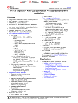
3 Block Diagram
Figure 2 shows the block diagram of the remote control with CapTIvate technology.
Figure 2. Block Diagram
3.1 MSP430FR2633
The MSP430FR2633 features:
• 16 CapTIvate technology inputs that support up to 64 electrodes in mutual-capacitance mode
• Parallel scanning of up to 4 electrodes at a time
• CapTIvate software library includes a preprogrammed 12KB of ROM
• 4 16-bit timers and a 16-bit counter-only real-time clock (RTC)
• 3 enhanced serial communications peripherals for UART, IrDA, SPI, and I
2
C
• 19 I/Os with 16 interrupt pins for wakeup from low-power modes
• High-performance, 8-channel 10-bit analog-to-digital converter (ADC)

Copyright © 2016, Texas Instruments Incorporated
Frequency
Hopping & Spread
Spectrum Oscillator
ui8FreqDiv
Voltage
Refrence
Refrence
Capacitors
Dedicated LDO
Regulator
blpmControl
CapTIvate
TM
Technology
Measurement Block(s)
IO Mux
bidleState
ui8TxPin
ui8TxBlock
ui8RxPin
ui8RxBlock
ui8RxPin
ui8RxBlock
C
m
Mutual
Mode
C
X
Self
Mode
Block n
Block 2
Block 1
Conversion
Control
+
Finite State
Machine
Logic
Event Timer
Interrupt Request
CAPT_IV_END_OF_CONVERSION
CAPT_IV_MAX_COUNT_ERROR
CAPT_IV_DETECTION
CAPT_IV_CONVERSION_COUNTER
Interrupt Request
CAPT_IV_TIMER
Low Frequency Clock
MSP Peripheral Bus
www.ti.com
Block Diagram
5
TIDUBT7A–July 2016–Revised December 2016
Submit Documentation Feedback
Copyright © 2016, Texas Instruments Incorporated
Touch Remote Control With CapTIvate™ Technology
3.1.1 CapTIvate™ Technology Peripheral
CapTIvate technology peripheral enables capacitive buttons, slider, GesturePad and proximity sensing on
the TIDM-CAPTIVATE-REMOTECONTROL.
CapTIvate technology peripheral provides the highest resolution capacitive-touch solution on the market
with high reliability and noise immunity at the lowest power. CapTIvate technology peripheral supports
concurrent self-capacitance and mutual-capacitance electrodes on the same design for maximum
flexibility.
Figure 3 shows a block diagram of the CapTIvate technology peripheral.
Figure 3. CapTIvate™ Technology Peripheral Block Diagram

PCB
Frontpanel
RxTx
PCB
Frontpanel
RxTx
Frontpanel
PCB
Frontpanel
PCB
Electrode
Electrode
System Design Theory
www.ti.com
6
TIDUBT7A–July 2016–Revised December 2016
Submit Documentation Feedback
Copyright © 2016, Texas Instruments Incorporated
Touch Remote Control With CapTIvate™ Technology
4 System Design Theory
4.1 CapTIvate™ Technology
CapTIvate technology is a dedicated MSP430 module that enables powerful capacitive sensing.
CapTIvate technology performs capacitance measurements by using a unique charge transfer technique.
CapTIvate technology provides a set of hardware and software tools for accommodating a wide range of
external capacitances. For more information on CapTIvate technology, refer to the CapTIvate™
Technology Guide.
4.1.1 Self-Capacitance Theory
The self-capacitance measurement is a way to measure change in capacitance with respect to earth
ground; this method is also referred to as surface capacitance. In a parallel-plate model, the electrode
defines one plate of the capacitor and the other plate is either ground or the user. A touch causes the
capacitance of the electrode to increase.
Figure 4 shows an example of self-capacitance theory.
Figure 4. Example for Self-Capacitance Theory
4.1.2 Mutual-Capacitance Theory
Like self-capacitance theory, mutual-capacitance theory involves measuring a change in capacitance.
However, mutual-capacitance electrodes have two separate electrode structures and require two pins from
the MCU: a transmit electrode and a receive electrode. When a user touches an area on the panel where
a Tx meets an Rx, the mutual capacitance between the Tx and Rx electrodes reduces. This interaction
disturbs the electric field propagation between the two electrodes that causes the reduction in mutual
capacitance. The human body is a conductor, and users couple to earth ground. Placing a finger between
two mutual-capacitance electrodes places ground between them. The ground reduces the electric-field
coupling between them, reducing the capacitance.
Figure 5 shows the example for mutual-capacitance theory.
Figure 5. Example for Mutual-Capacitance Theory
4.1.3 Wake-on-Proximity Mode
CapTIvate technology includes a finite state machine (FSM) that enables wake-on-proximity mode. In this
mode, the sensor has one cycle and no CPU operation is required to load new cycle-related values. The
wake-on-proximity mode reduces power consumption by keeping the MCU in a low-power mode while
measuring a single cycle until the selected wake-on-proximity sensor detects a proximity event.

B_0
B_5
B_6
B_7
G_0G_0
S_0
B_2
B_3
B_4
B_1
P_0
ON/OFF
MSP430
TM
CapTIvate
TM
MCUs
www.ti.com
System Design Theory
7
TIDUBT7A–July 2016–Revised December 2016
Submit Documentation Feedback
Copyright © 2016, Texas Instruments Incorporated
Touch Remote Control With CapTIvate™ Technology
4.2 Capacitive Touch Panel Design
The capacitive touch panel includes the following touch sensors:
• Eight touch buttons
• One touch slider for volume control
• One proximity sensor for grip protection
Figure 6 shows the capacitive touch panel with the touch sensor number.
Figure 6. Capacitive Touch Panel

System Design Theory
www.ti.com
8
TIDUBT7A–July 2016–Revised December 2016
Submit Documentation Feedback
Copyright © 2016, Texas Instruments Incorporated
Touch Remote Control With CapTIvate™ Technology
The capacitive touch panel is connected with the MSP430FR2633 through the pin assignment shown in
Table 2.
Table 2. Capacitive Touch Panel Pin Assignment
Controller Sensors
Port Use Mode Parallel Block Buttons CentralPad ProxPad Slider
CAP0.0 Unrestricted B0
CAP0.1 Unrestricted B1 RX00 RX00 RX00
CAP0.2 Unrestricted B2 TX00
CAP0.3 Unrestricted B3 TX00
CAP1.0 Unrestricted B0 TX01
CAP1.1 Unrestricted B1 RX01 RX01 RX01
CAP1.2 Unrestricted B2
CAP1.3 Unrestricted B3
CAP2.0 Unrestricted B0 TX02
CAP2.1 Unrestricted B1 RX02 RX02 RX02
CAP2.2 Unrestricted B2 TX03
CAP2.3 Unrestricted B3 TX04
CAP3.0 Unrestricted B0 TX00
CAP3.1 Unrestricted B1 RX03 RX03
CAP3.2 Unrestricted B2 TX01
CAP3.3 Unrestricted B3 RX00
Table 3 lists the touch sensor names and descriptions.
Table 3. Touch Sensor Descriptions
TOUCH SENSOR DESCRIPTION NUMBER NAME
Touch button
B_0 BUTTON_POWER
B_1 BUTTON_B
B_2 BUTTON_C
B_3 BUTTON_INPUT
B_4 BUTTON_MUTE
B_5 BUTTON_A
B_6 BUTTON_CHUP
B_7 BUTTON_CHDOWN
Touch slider S_0 SLIDER_VOL
Touch GesturePad G_0 CENTRALPAD
Proximity sensor P_0 PROXPAD

TX_A0
TX_A0
TX_A0
TX_A0
www.ti.com
System Design Theory
9
TIDUBT7A–July 2016–Revised December 2016
Submit Documentation Feedback
Copyright © 2016, Texas Instruments Incorporated
Touch Remote Control With CapTIvate™ Technology
4.2.1 Touch Buttons
The touch panel has eight mutual-capacitance buttons with four Rx pins and two Tx pins.
BUTTON_POWER is specified for the power-ON or power-OFF host functions, such as on a smart TV.
Other host functions use different buttons. The area of the rectangular electrode is 7 × 7 mm.
Figure 7 shows an example of the mutual-capacitance button pattern.
Figure 7. Example of Mutual-Capacitance Button Pattern
4.2.2 Touch Slider
The touch panel contains one mutual-capacitance slider with three Rx pins and one Tx pin. The slider is
used for host volume control. The area of the rectangular electrode is 35 mm × 9 mm.
Figure 8 shows an example of a mutual-capacitance slider.
Figure 8. Example of Mutual-Capacitance Slider Pattern

System Design Theory
www.ti.com
10
TIDUBT7A–July 2016–Revised December 2016
Submit Documentation Feedback
Copyright © 2016, Texas Instruments Incorporated
Touch Remote Control With CapTIvate™ Technology
4.2.3 Touch GesturePad
The touch panel contains one mutual-capacitance GesturePad with five Rx pins and five Tx pins. The
GesturePad acts as a 25-button matrix to detect the gestures of the user, such as a directional slide
starting from anywhere on the GesturePad moving up or down and right or left. Users can also tap on the
GesturePad to switch the focus and select. The area of the rectangular electrode is 43 mm × 43 mm.
Figure 9 shows an example of a touch GesturePad.
Figure 9. Example of Mutual-Capacitance GesturePad Pattern
4.2.4 Proximity Sensor
The touch panel has one self-capacitance proximity sensor that includes one Rx pin. The proximity sensor
acts as the grip detection sensors on the two edges of the remote control. These sensors are selected as
the wake-on-proximity sensor that can wake up the CPU when the remote control is gripped in wake-on-
proximity mode. The touch sensor contains two rectangular electrodes that have each an area of 120 mm
× 4 mm.
Figure 10 shows an example of a self-capacitance proximity sensor.
Figure 10. Example of Self-Capacitance Proximity Sensor Pattern

www.ti.com
System Design Theory
11
TIDUBT7A–July 2016–Revised December 2016
Submit Documentation Feedback
Copyright © 2016, Texas Instruments Incorporated
Touch Remote Control With CapTIvate™ Technology
4.3 Communication Interface
The remote control with CapTIvate technology supports various communication interfaces for future
application extensions. By default, a CC2650EM-7ID board can be connected with the remote control with
CapTIvate technology board for Bluetooth low energy communication to the host. Users can connect other
communication boards to the CONN Header with UART_1 or I
2
C.
Table 3 lists the hardware communication interfaces.
Table 4. Hardware Communication Interfaces
COMMUNICATION INTERFACE HARDWARE CONNECTOR
UART_1
Connector with CC2650EM-7ID
CONN header, unshrouded
I
2
C CONN header, unshrouded
4.3.1 Touch Command on UART Interface
The touch command can be reported by the UART_1 communication interface. A CC2650EM-7ID board
must be connected when using the UART to Bluetooth low energy bridge design (TIDC-SPPBLE-SW-RD)
as the wireless communication part with the host.
Table 4 lists the default UART settings used in this TI Design.
Table 5. Default UART Settings
UART PARAMETERS DEFAULT VALUE
Baud rate 115200
Data length 8
Parity None
Stop bits 1
Flow control None
The UART_1 touch command packets have a fixed length of 16 bits.
Table 5 lists the format of command packets.
Table 6. Command Packet Formats
BIT [15:12] COMMAND
DIRECTION
BIT [11:8] TOUCH SENSOR BIT [7:0] COMMAND DATA
0h: Remote control to the host
1h: Host to the remote control
1h: Touch GesturePad
11h: GESTUREPAD_SLIDE_UP
12h: GESTUREPAD_SLIDE_DOWN
13h: GESTUREPAD_SLIDE_LEFT
14h: GESTUREPAD_SLIDE_RIGHT
21h: GESTUREPAD_TAP
3h: Touch button
00h: BUTTON_POWER
01h: BUTTON_CHUP
02h: BUTTON_CHDOWN
03h: BUTTON_A
04h: BUTTON_B
05h: BUTTON_C
06h: BUTTON_INPUT
07h: BUTTON_MUTE
5h: Touch slider
xxh: SLIDER_POSITION
Fh: Error
FFh: Error
0h: Null
00h: Null

System Design Theory
www.ti.com
12
TIDUBT7A–July 2016–Revised December 2016
Submit Documentation Feedback
Copyright © 2016, Texas Instruments Incorporated
Touch Remote Control With CapTIvate™ Technology
4.4 Indicator
The remote control with CapTIvate technology uses two LED indicators to indicate the power status and
touch operation. Table 6 lists the specifications of the LED indicators.
Table 7. LED Indicator Specifications
LED INDICATOR SPECIFICATION
Green LED Indicate the Wake-On-Touch with grip detection
Red LED Indicate the command transmitting
A haptic circuitry is also available on the TI Design board.

Remote Control Start
System Initialization
CapTIvate
Configuration
(1)
CapTIvate Handle
Touch
Detected ?
Analyze CapTIvate
Raw Data
Command
Available
(5)(6)
?
Inactivity Time
> 1s ?
Sleep to Next Wake-
on-Proximity Mode
Scan Cycle
(4)
Proximity Sensor
Detected?
Sleep to Next Active
Mode Scan Cycle
(3)
Send
Command to
the BLE
Server
(2)
Active Scan ModeWake-on-Proximity Mode
Receive
Command from
the BLE
Client
(2)
PC Host Start
UART to BLE Bridge
Initialization
PC COM Port
Connection
Analyze Command
Display Touch
Operation
PC COM Port
Disconneced?
Stop
Initialization Routine
Scan the Proximity
Sensor
Blink the Red LED
Indicator
Blink the Green LED
Indicator
Y
N
Y
N
UART to
BLE Bridge
Y
N
Y
N
Y
N
Copyright © 2016, Texas Instruments Incorporated
www.ti.com
System Design Theory
13
TIDUBT7A–July 2016–Revised December 2016
Submit Documentation Feedback
Copyright © 2016, Texas Instruments Incorporated
Touch Remote Control With CapTIvate™ Technology
4.5 Software
Figure 11 shows the experience software flowchart.
Figure 11. Experience Software Flow Chart

System Design Theory
www.ti.com
14
TIDUBT7A–July 2016–Revised December 2016
Submit Documentation Feedback
Copyright © 2016, Texas Instruments Incorporated
Touch Remote Control With CapTIvate™ Technology
NOTE:
1. See Section 4.2 for CapTIvate configuration.
2. The BLE server is connected with the remote control. The BLE client is
connected with the PC host.
3. The active mode scan rate is 33 ms.
4. The wake-on-proximity mode scan rate is 200 ms.
5. See Section 4.3.1 for available touch command specification.
6. For the buttons’ touch operation, the consecutive touch, which is detected within
1.5 s for BUTTON_POWER button or 0.5 s for the other buttons, does not make
sense for a real remote control operation and will be ignored.
4.5.1 Remote Control Software Flow
In the initialization routine, DCO is configured to 8 MHz and stabilized by the FLL. The SMCLK is
configured to 2 MHz. The external crystal XT1 with 32768-Hz typical frequency is selected as a clock
reference into FLL. The MSP430 pins are configured, and unused pins are configured to output low for the
lowest power consumption. The CapTIvate touch panel is configured by CapTIvate library based on the
settings described in Section 4.2.
In the main loop, the remote control will run as two different modes, active scan mode and wake-on-
proximity mode. The remote control will firstly run into active scan mode and scan for any of touch
operation every 33 ms. If a touch operation is detected, the raw data of conversion result can be analyzed
and a command, if available, will be sent to the connected BLE server board via the UART_1 interface.
The red LED indicator will be blinked. If BLE server board receives the touch command, it will transmit the
command to BLE client board through BLE wireless.
If there is no touch operation been detected more than 1 second, the remote control will go to wake-on-
proximity mode and just scan the proximity sensor. In wake-on-proximity mode, the scan rate will be slow
down to 200ms and the other touch panel will not be scanned. The remote control will blink the green LED
indicator after the proximity sensor being detected and wake up to active scan mode.
4.5.2 PC Host Software Flow
The PC host can connect to the BLE client board via the COM port. After the UART to BLE Bridge
Initialization (refer to section 6.2 for the details), the BLE client board will wait for a command from BLE
server and transmit to PC host. The GUI on PC host can analyze the command received from BLE client
and display the touch operation.

BLE client part acted with
CC2650EM-7ID board
BLE server part acted with
CC2650EM-7ID board
To PC via the
USB cable
Connect with
remote control
via the UART_1
www.ti.com
Getting Started Hardware
15
TIDUBT7A–July 2016–Revised December 2016
Submit Documentation Feedback
Copyright © 2016, Texas Instruments Incorporated
Touch Remote Control With CapTIvate™ Technology
5 Getting Started Hardware
5.1 UART_1 to Bluetooth
®
Low Energy Bridge
The remote control with CapTIvate technology uses the UART to BLE bridge (TIDC-SPPBLE-SW-RD) as
the wireless communication part with the host. The user can follow the instructions in Section 2.1.3 of [2]
to set up the UART to Bluetooth low energy bridge.
A CC2650EM-7ID board, which has been downloaded the SPPBLEServer project, can act as the BLE
server part and connect to the remote control board via the RF1/RF2 connector.Figure 12 shows the
connector for the CC2650EM-7ID board.
Figure 12. Connector of CC2650EM-7ID Board
Figure 13 shows the UART_1 to BLE Bridge hardware.
Figure 13. UART_1 to BLE Bridge Hardware
The remote control connected with BLE server part, which is a CC2650EM-7ID board running the
SPPBLEServer project.

BLE Client Part
Remote Control
with BLE Server Part
USB cable
Getting Started Hardware
www.ti.com
16
TIDUBT7A–July 2016–Revised December 2016
Submit Documentation Feedback
Copyright © 2016, Texas Instruments Incorporated
Touch Remote Control With CapTIvate™ Technology
Another CC2650EM-7ID board which been downloaded the SPPBLEClient project can act as the BLE
client part and connect to the SmartRF06 board. The SmartRF06 board with BLE client part can be
connected with PC via the USB cable.
Figure 14 shows the whole hardware system setup for remote control.
Figure 14. Hardware System Setup for Remote Control
5.2 Communication Interface Extension
This TI Design supports communication interface extension with UART or I
2
C. Users can connect a
communication module to J6 on the remote control board.
Figure 13 shows the connector for the Communication Interface Extension.
Figure 15. Connector for Communication Interface Extension
Table 7 lists the pin assignment of J6.
Table 8. Pin Assignments
PIN NO. ASSIGNMENT
J6-1 TXD_MSP
J6-2 RXD_MSP
J6-3 P1.1_MSP
J6-4 P1.0_MSP
J6-5 SDA_MSP
J6-6 SCL_MSP
J6-7 GND
6 Getting Started Firmware
6.1 Download Project Using CCS v6
The software project of this TI Design can be downloaded here.

Power on the CLE
Server and Client
Part
3UHVV³83´WRLQLWLDWH
a device discovery on
the client side
3UHVV³/()7´XQWLO
the correct server
device is found
3UHVV³6(/(&7´WR
connect to the server
device
BLE connected
www.ti.com
Getting Started Firmware
17
TIDUBT7A–July 2016–Revised December 2016
Submit Documentation Feedback
Copyright © 2016, Texas Instruments Incorporated
Touch Remote Control With CapTIvate™ Technology
To download the project using CCS v6, follow these instructions:
1. Insert the software project (Menu → Project → Import CCS Projects).
2. Click to build the project (CTRL + B, Menu → Project → Build All).
3. Connect the SBW interface (pins J32-2 and J32-3) from the reference design board to the MSP-FET
tool.
4. Connect the MSP-FET tool to the PC with the USB cable.
5. Click to download the project to the device (FLL, Menu → Run → Debug).
6. Click to execute the program (or close the debugger and reset the device).
Table 8 lists the pin assignment of J32.
Table 9. Pin Assignments
PIN NUMBER ASSIGNMENT
J32-1 GND
J32-2 RST/SBWTDIO
J32-3 TEST/SBWTCK
J32-4 BRIDGE_TXD
J32-5 BRIDGE_RXD
J32-6 GND
J32-7 VCC_BAT
6.2 Setup the UART to BLE Bridge
After power on, the SmartRF06 board (BLE client part), the remote control (BLE server part), and the
buttons (UP/LEFT/SELECT) on the SmartRF06 board can be used to setup the UART to BLE bridge.
Figure 16 shows the flow of setup the communication.
Figure 16. BLE Communication Setup Flow

Getting Started Firmware
www.ti.com
18
TIDUBT7A–July 2016–Revised December 2016
Submit Documentation Feedback
Copyright © 2016, Texas Instruments Incorporated
Touch Remote Control With CapTIvate™ Technology
6.3 Demonstration With PC GUI
6.3.1 Remote Control Touch Operation
The remote control touch panel supports below operations:
1. Touch Button_Power: Touch to switch the ON/OFF power switch of a TV set. The consecutive touch
within 1.5 s will be ignored.
2. General Touch Buttons: General purpose buttons of a TV set. The consecutive touch within 0.5 s will
be ignored.
3. Touch Slider: Slider to control the volume of a TV set. The touched position will be the volume value.
4. Touch GesturePad: GesturePad that supports gestures of sliding right, left, up, and down as well as a
single tap on the pad.
6.3.2 Setup the Demonstration With Online GUI Tool
The GUI demonstration tool was developed by GUI Composer v2.0 and can be launched on TI Cloud
Tools website and run online. Users can go to the Gallery of TI Cloud Tools, and search with
GUI_for_TIDM-CAPTIVATE-REMOTECONTROL. The tool will be shown on the dashboard of the gallery.
Figure 17. GUI_for_TIDM-CAPTIVATE-REMOTECONTROL on Dashboard of Gallery

www.ti.com
Getting Started Firmware
19
TIDUBT7A–July 2016–Revised December 2016
Submit Documentation Feedback
Copyright © 2016, Texas Instruments Incorporated
Touch Remote Control With CapTIvate™ Technology
Users can click the tool and run it online. Figure 18 shows the GUI tool view running online.
Figure 18. GUI Tool View Running Online
Users can follow the below steps to setup the GUI demonstration:
1. Plug in your SmartRF06 board (BLE client part) the PC.
2. Confirm the COM port number of the USB Serial Port, which can be found in the list of Computer
Management → Device Manager → Ports (COM & LPT).
3. Choose your COM port by clicking on Options → Serial Port (the main window upper left corner shown
in Figure 18) and choosing COM port. Keep the BaudRates to be 115200 by the default setting. Then
click CONFIGURE to connect the COM port. The COM port configuration window is shown in
Figure 19.

Getting Started Firmware
www.ti.com
20
TIDUBT7A–July 2016–Revised December 2016
Submit Documentation Feedback
Copyright © 2016, Texas Instruments Incorporated
Touch Remote Control With CapTIvate™ Technology
Figure 19. COM Port Configuration
4. Wait until COMxx : 115200 waiting for data ... appears in the lower left corner of the main window.
5. Press on the remote control touch panel to see events being reflected in the GUI.
NOTE: The above instructions for the GUI demonstration can be shown by clicking on Help → View
README.md.
/