Page is loading ...

Power Management
Isolated AC/DC
Supply
System Power
AFE031
Processor
Host
MCU
UART
Clock
ADC
McBSP
PGA
PA
Surge
Protector
Coupling
Transformer
HV Cap
Power
Lines
TI Designs
System on Module for Power Line Communication
(CENELEC Frequency Band)
TI Designs Design Features
TI Designs provide the foundation that you need • Small Size: 1.5" x 1.9"
including methodology, testing and design files to
• G3-PLC Compatible
quickly evaluate and customize the system. TI Designs
• F28PLC84 PLC Engine With VCU
help you accelerate your time to market.
• Supports Cenelec A Frequency Band
Design Resources
• AFE031 Integrated Analog Front-End (AFE)
• 34-Pin Mini Header for Interfacing Other Designs
Design Folder
TIDM-SOMPLC-F28PLC84
• Multiple Serial Communications Interfaces
TMDSPLCKIT-V4 Tool Folder
Available Including UART, SPI, I2C, and CAN
TMS320F28PLC84 Product Folder
AFE031 Product Folder
• Additional ADC Interface
TPS62240 Product Folder
• Additional GPIO Interfaces
TPS3828-33 Product Folder
Featured Applications
SN74LVC2G07 Product Folder
• PLC Modem
• Smart E-Meter: AMR and AMI
ASK Our E2E Experts
WEBENCH® Calculator Tools
• Solar Power Inverter
An IMPORTANT NOTICE at the end of this TI reference design addresses authorized use, intellectual property matters and other
important disclaimers and information.
All trademarks are the property of their respective owners.
1
TIDU847–March 2015 System on Module for Power Line Communication (CENELEC Frequency
Band)
Submit Documentation Feedback
Copyright © 2015, Texas Instruments Incorporated

SOMPLC Description
www.ti.com
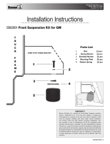
1 SOMPLC Description
The SOMPLC-F28PLC84 is a single-board System on Module(SOM) for PLC in the Cenelec A frequency
band. This single hardware design supports several popular PLC industry standards including G3-PLC.
TI's certified PLC software is available along with the SOMPLC-F28PLC84. Engineers can take the SOM
design and integrate it into their overall system board or keep the design as an add-on board to their
application. The only additional hardware required is the AC mains line coupling circuitry. The included
hardware schematics and Gerber files simplify the task for engineers to add PLC to their end system.
OEMs will benefit from having the ability to rapidly evaluate and prototype PLC technology in their
application.
2 System Description
The TMS320F28PLC84 PLC MCU is optimized to meet the requirements for PLC networks in Smart Grid
deployments around the world. The F28PLC84 MCU features the C28x 32-bit CPU and ROM codes for
application boot loader and some PHY libs, which is capable of executing the narrowband OFDM PLC
modem standards. These modem standards adhere to key international and industry standards such as
PRIME, G3-PLC, IEEE-1901.2, and ITU G.9903/9904 in the CENELEC frequency bands. The F28PLC84
MCU is optimized to work with the AFE031. The AFE031 is an integrated PLC AFE that is capable of a
transformer coupled connected to the AC mains power line. The device is ideal for driving high-current,
low-impedance lines driving up to 1.9 A into reactive loads. The AFE031 is compliant to CENELEC A, B,
C, and D (EN50065-1, -2, -3, and -7, respectively).
2.1 PLC Development Kit Components
The development kit includes the following hardware:
• Two sets of development board with each set containing:
– SOMPLC-F28PLC84 (TMS320F28PLC84+AFE031)
– One docking board
The development kit includes the following software:
• PLC binaries
• PC software and GUI
– Zero configuration GUI
The PLC software package includes the following documents:
• Software API specification
– Host message protocol specifications
• Hardware documents
– AFE daughter card schematics and Gerber files
– Docking board/SOM schematics and Gerber files
– Bill of Materials (BOM)
2
System on Module for Power Line Communication (CENELEC Frequency TIDU847–March 2015
Band)
Submit Documentation Feedback
Copyright © 2015, Texas Instruments Incorporated

ON
1 2
ON
1 2
FLASH Boot Mode (Default Setting)
Position 1: OFF
Position 2: OFF
SCI-A Boot Mode
Position 1: OFF
Position 2: ON
www.ti.com
Boot Modes (SW1 Positions)
3 Boot Modes (SW1 Positions)
Boot mode can be selected using the switch SW1. Figure 1 describes the available settings:
Figure 1. Boot Modes
4 UART SCI Communication
To communicate with the SCI, meet the following requirements:
• Baud Rate = 57600
• Message Data Bits = 8
• Stop Bits = One
• Parity = None
• Handshake = None
• RTS Enable = True
NOTE: The SOMPLC does not have a RS-232 driver. Consider communications to RS-232 devices
external to this design.
3
TIDU847–March 2015 System on Module for Power Line Communication (CENELEC Frequency
Band)
Submit Documentation Feedback
Copyright © 2015, Texas Instruments Incorporated

SOMPLC 34-Pin Definition
www.ti.com
5 SOMPLC 34-Pin Definition
This module supports the following interfaces:
Required Connections Optional Connections
• SCI (UART) • ADC
• Line • GPIOs
• 15 V • SCI (UART)
• 3V3 • CAN
• GND • SPI
• I
2
C
• Zero Cross
• Analog GND
4
System on Module for Power Line Communication (CENELEC Frequency Band) TIDU847–March 2015
Submit Documentation Feedback
Copyright © 2015, Texas Instruments Incorporated

www.ti.com
SOMPLC 34-Pin Definition
Table 1. 34-Pin Connector
PIN# NAME I/O ELECTRICAL DESCRIPTION
1 L1 I/O 0 V (GND) Neutral (analog ground), connected to the PL coupler
0 V
2 L2 I/O Analog PLC signal, connected to the PL coupler
(±6-V Peak)
3 NC NC — Unused
4 NC NC — Unused
5 GND — — Ground
6 GND — — Ground
Power supply pin (15 V). Peak current 400 mA in transmit mode (average
7 V15 — 15 to 18 V
100 mA).
8 3V3 — 3.14 to 3.47 V CPU and Logic Digital Power pin (3.3 V). Max current 1000 mA.
System enable (logical level, active high). Controls power up/down
9 EN I-I/O –0.3 V to VCC+0.3 V function of the module. When low, the module goes to power down mode.
This feature is not yet implemented in software or GPIO13.
Buffered ZC input. This input must be isolated from the power line before
10 ZC I –0.5 to 6.5 V
entering this pin.
11 RX-A I –0.3 V to VCC+0.3 V Asynchronous serial host-transmit, SCI-A
12 TX-A O –0.3 V to VCC+0.3 V Asynchronous serial host-receive, SCI-A
13 Phase B/GPIO I-I/O –0.3 V to VCC+0.3 V Phase B Enable signal (for 3-phase selection) or GPIO5
14 I/O –0.3 V to VCC+0.3 V Phase C enable signal (for 3-phase selection ) or GPIO10
15 I/O –0.3 V to VCC+0.3 V I
2
C data pin
16 I –0.3 V to VCC+0.3 V I
2
C clock pin
17 I –0.3 V to VCC+0.3 V Unused ADC input. (ADC-B0)
18 — — Analog ground
19 I/O –0.3 V to VCC+0.3 V Unused multi-purpose I/O, GPIO26
20 — — Ground
21 I/O –0.3 V to VCC+0.3 V Unused multi-purpose I/O, GPIO27
22 — — Ground
23 I-I/O –0.3 V to VCC+0.3 V CAN RX interface or GPIO30
24 O-I/O –0.3 V to VCC+0.3 V CAN TX interface or GPIO31
25 I –0.3 V to VCC+0.3 V SPI clock or general purpose I/O (GPIO18)
26 I –0.3 V to VCC+0.3 V SPI slave transmit enable or general purpose I/O (GPIO19)
27 I –0.3 V to VCC+0.3 V SPI slave in, master out or general purpose I/O (GPIO16)
28 O –0.3 V to VCC+0.3 V SPI master in, slave out or general purpose I/O (GPIO17).
29 I –0.3 V to VCC+0.3 V Reset of SOMPLC (active low)
30 I/O –0.3 V to VCC+0.3 V Unused multi-purpose I/O pin, GPIO04.
31 NC — Unused
32 NC — Unused
33 I –0.3 V to VCC+0.3 V Asynchronous serial host-receive, SCI-B
34 O –0.3 V to VCC+0.3 V Asynchronous serial host-transmit, SCI-B
5
TIDU847–March 2015 System on Module for Power Line Communication (CENELEC Frequency
Band)
Submit Documentation Feedback
Copyright © 2015, Texas Instruments Incorporated

1
2
3
4
5
6
8
7
9
10
11
12
13
14
15
16
17
18
19
20
21
22
23
24
25
26
27
28
29
30
31
32
33
34
Mechanical Specification
www.ti.com
6 Mechanical Specification
The connectors used on the SOMPLC are as follows:
• A male 0.05-mil header (2×17) is placed on the SOMPLC module.
– This connector is keyed so that the module cannot be placed backwards.
– An example part that will fit this design is a Sullins Connector Solutions, Part number: SBH31-
NBPB-D17-SP-BK, Digikey Part number: S9108-ND
• A female 0.05-mil receptacle (2×17) should be used on the host board to mate with the SOMPLC
module.
– This connector is keyed and should follow the appropriate orientation as the male connector.
– An example part that will fit this design is a Sullins Connector Solutions, Part Number: SFH31-
NPPB-D17-SP-BK, Digikey Part Number:S9117-ND
The top view of the female connector which would be placed on the host board is shown in Figure 2.
Figure 2. Pin Female Connector Top View
6
System on Module for Power Line Communication (CENELEC Frequency TIDU847–March 2015
Band)
Submit Documentation Feedback
Copyright © 2015, Texas Instruments Incorporated

www.ti.com
PLC SOM Programming
7 PLC SOM Programming
Depending on the end use of the SOM, different versions of the PLC software may be programmed to the
module.
For this design, download the G3-PLC software package from the link given in Section 10.6 and check out
the G3-PLC binaries (.hex/.out/.sbin) under installation directory.
7.1 Using the XDS100 and CodeSkin to Program the F28PLC84 MCU
Programming with this method eliminates the need for Code Composer Studio™ (CCS) to load the
release(.out) file. A .hex release file is used instead; therefore, installing CCS is not necessary.
1. Install the desired Texas Instruments PLC Development Package from www.ti.com/plc.
2. Download, install, and start the latest C2Prog from http://www.codeskin.com.
3. Set switch SW1 to "FLASH Boot Mode" as described in Section 3.
4. Connect a Texas Instruments XDS100 class emulator to the SOM module using the 14-Pin JTAG
header.
5. Power up SOM module by applying both 15 V and 3.3 V through the 34-pin host connector.
6. Program the *.hex (located in c:\Texas Instruments\<PackageName>\SW\bin) as shown in Figure 3.
Select "28069,67,66" in the Target pull-down and "JTAG" in the Options pull-down.
Figure 3. Selecting G3-PLC Binary to be Flashed (Through XDS100)
7
TIDU847–March 2015 System on Module for Power Line Communication (CENELEC Frequency
Band)
Submit Documentation Feedback
Copyright © 2015, Texas Instruments Incorporated

PLC SOM Programming
www.ti.com
7. Click on the Configure Ports button and set the JTAG port to "XDS100v1".
Figure 4. Selecting JTAG Port (Through XDS100)
8. Start flashing the F28069.
Figure 5. Flashing G3-PLC Firmware (Through XDS100)
9. Once the programming procedure is complete, power cycle the device.
8
System on Module for Power Line Communication (CENELEC Frequency TIDU847–March 2015
Band)
Submit Documentation Feedback
Copyright © 2015, Texas Instruments Incorporated

www.ti.com
PLC SOM Programming
7.2 Using CCS and JTAG Emulator to Program the F28PLC84 MCU
If the XDS100 emulator is not available, it will be necessary to use CCS and a XDS510 or XDS560
emulator to program the device. Install CCS V5.5 or higher before following this procedure:
1. Install the desired Texas Instruments PLC Development Package from www.ti.com/plc.
2. Set switch SW1 to "FLASH Boot Mode" as described in Section 3. When a JTAG emulator is used, it is
capable of interrupting the set boot mode to gain control of the MCU. When the programming
procedure is complete, set the mode to "FLASH Boot Mode" for the SOM module to continue to work
properly.
3. Power up SOM module by applying both 15 V and 3.3 V through the 34-pin host connector.
4. Connect the emulator to the SOM module with the 14-pin JTAG cable.
5. Open CCS.
6. Create a F28069 target configuration.
7. Connect to the F28069 device.
8. Load the PLC specific .out firmware located in c:\Texas Instruments\<PackageName>\SW\bin. CCS
will automatically flash the firmware onto the F28069 device.
9
TIDU847–March 2015 System on Module for Power Line Communication (CENELEC Frequency
Band)
Submit Documentation Feedback
Copyright © 2015, Texas Instruments Incorporated

Test Setup
www.ti.com
8 Test Setup
To test the SOM modules, the operator will need the following items:
• A host computer running Windows® XP® or Windows 7® and two available USB ports
• Two SOM docking stations
• 15-V external power supply for each docking station
• Power line connector for each docking station
• USB cable for connecting to Host PC for each docking station
– A single Host PC can be shared between the two kits
• Zero configuration GUI
– Requires a modified .config file
10
System on Module for Power Line Communication (CENELEC Frequency TIDU847–March 2015
Band)
Submit Documentation Feedback
Copyright © 2015, Texas Instruments Incorporated

ON
ON
1 2 3
1 2
SW1
SW2
Default settings
SW2 (SCI-A)
34 pin SOM
Module Connector
SOMPLC Docking Station
Power Grid
Connection
SW1 (SCI-B) SW3
USB
(SCI-A/SCI-B)
External Power
Connector
www.ti.com
Test Setup
8.1 Setup
1. Plug in the included SOM module to each 34-pin SOM module connector.
Figure 6. SOMPLC Docking Station
2. Connect Neutral and Line (marked with words on AC Power Cable) to the power grid connector P1 of
each kit; make sure the neutral and line connections are not shorted.
Figure 7. Line Connection
3. Ensure the position of switches SW1 and SW2 are set to default setting as shown in fig to
communicate to PC GUI through SCI-A.
Figure 8. Software Configuration
11
TIDU847–March 2015 System on Module for Power Line Communication (CENELEC Frequency
Band)
Submit Documentation Feedback
Copyright © 2015, Texas Instruments Incorporated

OFF (Default setting)
Turn to the inside of board
ON
Turn to the outside of board
Test Setup
www.ti.com
8.2 Power Up
1. Connect the 15-V wall-mounted power supply to the AC receptacle of each kit.
Figure 9. SW3
2. Turn ON Switch SW3 of each kit to power the boards.
8.3 Connecting to a PC
1. Plug in the micro-USB to the kit and connect the USB cable to the PC. Repeat this step for the second
kit.
NOTE: The program may ask for USB-Serial drivers to be installed. If this occurs, please proceed to
install the drivers. The drivers can be found in C:\Texas
Instruments\<PackageName>\XDS100 Drivers. Reboot your PC after the drivers are
installed, even if you are not asked by windows to do so.
2. Verify the modems have been installed correctly by using the Device Manager (Start→Control
Panel→System→Device Manager→Ports)
NOTE: The four ports on picture are for two boards.
Figure 10. Device Manager: Port Configuration
12
System on Module for Power Line Communication (CENELEC Frequency TIDU847–March 2015
Band)
Submit Documentation Feedback
Copyright © 2015, Texas Instruments Incorporated

www.ti.com
Testing
9 Testing
1. Install the "Zero Configuration" tool from C:\TexasInstruments\<PackageName>\Tools, and launch it.
When operating one PC, it will be necessary to launch two instances, one for each modem.
2. When the Zero Configuration GUI opens, it will use the first available COM port to attach to a PLC.
NOTE: Ensure Diagnostic Port/Data Port is configured to SCI-A by selecting CTRL+A in GUI
window.
Figure 11. Zero Configuration GUI
13
TIDU847–March 2015 System on Module for Power Line Communication (CENELEC Frequency
Band)
Submit Documentation Feedback
Copyright © 2015, Texas Instruments Incorporated

SCI-A or SCI-B
Power Line
Unit 2Unit 1
Testing
www.ti.com
3. Connect each PLC kit to the power line. Ensure that devices are connected on same power line phase.
WARNING
HIGH VOLTAGE! Use caution when connecting to the power grid. If
there is concern about connecting to the power grid, use a power
strip to connect the two modems together. In this case, the power
strip does not need to be plugged into the power grid.
Figure 12. Testing Setup
14
System on Module for Power Line Communication (CENELEC Frequency TIDU847–March 2015
Band)
Submit Documentation Feedback
Copyright © 2015, Texas Instruments Incorporated

www.ti.com
Testing
4. Enter the desired text into the Message Window. Press the Send Message button. The message will
then be received by the other GUI.
Figure 13. P2P Test With Zero Configuration GUI
15
TIDU847–March 2015 System on Module for Power Line Communication (CENELEC Frequency
Band)
Submit Documentation Feedback
Copyright © 2015, Texas Instruments Incorporated

Testing
www.ti.com
The File Transfer function contained in the bottom left hand corner of GUI option can be used to
transfers files.
Figure 14. File Transfer TX
16
System on Module for Power Line Communication (CENELEC Frequency TIDU847–March 2015
Band)
Submit Documentation Feedback
Copyright © 2015, Texas Instruments Incorporated

www.ti.com
Testing
5. Click on the Browse button to display the standard windows file chooser dialog to choose the file you
wish to transfer. Only one file at a time may be chosen for the file transfer.
After the file is chosen, click on the Transfer File button. The other PLC must also be controlled by the
Zero Configuration GUI.
When the transfer starts the GUI will display a progress bar on both Zero Configuration GUIs. The GUI
in Figure 15 is the receiving Zero Configuration GUI and displays the path and file name where the
received file is being copied. The user is not allowed to change the directory path of the received file.
Figure 15. File Transfer RX
17
TIDU847–March 2015 System on Module for Power Line Communication (CENELEC Frequency
Band)
Submit Documentation Feedback
Copyright © 2015, Texas Instruments Incorporated

Testing
www.ti.com
When the file transfer is complete the message box shown in Figure 16 will be displayed on both Zero
Configuration GUIs.
Figure 16. Message Box
If the file transfer fails, the one of following message boxes will be displayed by the sending GUI.
Figure 17. Case 1: File Transfer Failed Figure 18. Case 2: File Transfer Failed
18
System on Module for Power Line Communication (CENELEC Frequency TIDU847–March 2015
Band)
Submit Documentation Feedback
Copyright © 2015, Texas Instruments Incorporated

www.ti.com
Design Files
10 Design Files
10.1 Schematics
To download the most recent schematics, see the design files at TIDM-SOMPLC-F28PLC84.
NOTE: The transformer may not be necessary in a production design.
10.2 Bill of Materials
To download the most recent bill of materials (BOM), see the design files at TIDM-SOMPLC-F28PLC84.
10.3 Layer Plots
To download the most recent layer plots, see the design files at TIDM-SOMPLC-F28PLC84.
10.4 Gerber Files
To download the most recent Gerber files, see the design files at TIDM-SOMPLC-F28PLC84.
10.5 Assembly Drawings
To download the most recent assembly drawings, see the design files at TIDM-SOMPLC-F28PLC84.
10.6 Software Files
To download the most recent software files, see the design files at TIDM-SOMPLC-F28PLC84.
11 About the Author
WONSOO KIM is a system applications engineer at Texas Instruments, where he is responsible for
providing technical support and training on communication software and system for smart grid applications
and driving solutions for Smart Grid and Metering, and working on defining future requirements in
roadmap. He received the Ph.D. degree in electrical and computer engineering, the University of Texas at
Austin.
NAVEEN KALA is a system applications engineer at Texas Instruments, where he is responsible for
providing technical support and training on PLC hardware and driving solutions for Smart Grid and
Metering, and working on defining future requirements in roadmap. He received the M.Eng. degree in
electrical and computer engineering from the University of Iowa.
19
TIDU847–March 2015 System on Module for Power Line Communication (CENELEC Frequency
Band)
Submit Documentation Feedback
Copyright © 2015, Texas Instruments Incorporated

IMPORTANT NOTICE FOR TI REFERENCE DESIGNS
Texas Instruments Incorporated ("TI") reference designs are solely intended to assist designers (“Buyers”) who are developing systems that
incorporate TI semiconductor products (also referred to herein as “components”). Buyer understands and agrees that Buyer remains
responsible for using its independent analysis, evaluation and judgment in designing Buyer’s systems and products.
TI reference designs have been created using standard laboratory conditions and engineering practices. TI has not conducted any
testing other than that specifically described in the published documentation for a particular reference design. TI may make
corrections, enhancements, improvements and other changes to its reference designs.
Buyers are authorized to use TI reference designs with the TI component(s) identified in each particular reference design and to modify the
reference design in the development of their end products. HOWEVER, NO OTHER LICENSE, EXPRESS OR IMPLIED, BY ESTOPPEL
OR OTHERWISE TO ANY OTHER TI INTELLECTUAL PROPERTY RIGHT, AND NO LICENSE TO ANY THIRD PARTY TECHNOLOGY
OR INTELLECTUAL PROPERTY RIGHT, IS GRANTED HEREIN, including but not limited to any patent right, copyright, mask work right,
or other intellectual property right relating to any combination, machine, or process in which TI components or services are used.
Information published by TI regarding third-party products or services does not constitute a license to use such products or services, or a
warranty or endorsement thereof. Use of such information may require a license from a third party under the patents or other intellectual
property of the third party, or a license from TI under the patents or other intellectual property of TI.
TI REFERENCE DESIGNS ARE PROVIDED "AS IS". TI MAKES NO WARRANTIES OR REPRESENTATIONS WITH REGARD TO THE
REFERENCE DESIGNS OR USE OF THE REFERENCE DESIGNS, EXPRESS, IMPLIED OR STATUTORY, INCLUDING ACCURACY OR
COMPLETENESS. TI DISCLAIMS ANY WARRANTY OF TITLE AND ANY IMPLIED WARRANTIES OF MERCHANTABILITY, FITNESS
FOR A PARTICULAR PURPOSE, QUIET ENJOYMENT, QUIET POSSESSION, AND NON-INFRINGEMENT OF ANY THIRD PARTY
INTELLECTUAL PROPERTY RIGHTS WITH REGARD TO TI REFERENCE DESIGNS OR USE THEREOF. TI SHALL NOT BE LIABLE
FOR AND SHALL NOT DEFEND OR INDEMNIFY BUYERS AGAINST ANY THIRD PARTY INFRINGEMENT CLAIM THAT RELATES TO
OR IS BASED ON A COMBINATION OF COMPONENTS PROVIDED IN A TI REFERENCE DESIGN. IN NO EVENT SHALL TI BE
LIABLE FOR ANY ACTUAL, SPECIAL, INCIDENTAL, CONSEQUENTIAL OR INDIRECT DAMAGES, HOWEVER CAUSED, ON ANY
THEORY OF LIABILITY AND WHETHER OR NOT TI HAS BEEN ADVISED OF THE POSSIBILITY OF SUCH DAMAGES, ARISING IN
ANY WAY OUT OF TI REFERENCE DESIGNS OR BUYER’S USE OF TI REFERENCE DESIGNS.
TI reserves the right to make corrections, enhancements, improvements and other changes to its semiconductor products and services per
JESD46, latest issue, and to discontinue any product or service per JESD48, latest issue. Buyers should obtain the latest relevant
information before placing orders and should verify that such information is current and complete. All semiconductor products are sold
subject to TI’s terms and conditions of sale supplied at the time of order acknowledgment.
TI warrants performance of its components to the specifications applicable at the time of sale, in accordance with the warranty in TI’s terms
and conditions of sale of semiconductor products. Testing and other quality control techniques for TI components are used to the extent TI
deems necessary to support this warranty. Except where mandated by applicable law, testing of all parameters of each component is not
necessarily performed.
TI assumes no liability for applications assistance or the design of Buyers’ products. Buyers are responsible for their products and
applications using TI components. To minimize the risks associated with Buyers’ products and applications, Buyers should provide
adequate design and operating safeguards.
Reproduction of significant portions of TI information in TI data books, data sheets or reference designs is permissible only if reproduction is
without alteration and is accompanied by all associated warranties, conditions, limitations, and notices. TI is not responsible or liable for
such altered documentation. Information of third parties may be subject to additional restrictions.
Buyer acknowledges and agrees that it is solely responsible for compliance with all legal, regulatory and safety-related requirements
concerning its products, and any use of TI components in its applications, notwithstanding any applications-related information or support
that may be provided by TI. Buyer represents and agrees that it has all the necessary expertise to create and implement safeguards that
anticipate dangerous failures, monitor failures and their consequences, lessen the likelihood of dangerous failures and take appropriate
remedial actions. Buyer will fully indemnify TI and its representatives against any damages arising out of the use of any TI components in
Buyer’s safety-critical applications.
In some cases, TI components may be promoted specifically to facilitate safety-related applications. With such components, TI’s goal is to
help enable customers to design and create their own end-product solutions that meet applicable functional safety standards and
requirements. Nonetheless, such components are subject to these terms.
No TI components are authorized for use in FDA Class III (or similar life-critical medical equipment) unless authorized officers of the parties
have executed an agreement specifically governing such use.
Only those TI components that TI has specifically designated as military grade or “enhanced plastic” are designed and intended for use in
military/aerospace applications or environments. Buyer acknowledges and agrees that any military or aerospace use of TI components that
have not been so designated is solely at Buyer's risk, and Buyer is solely responsible for compliance with all legal and regulatory
requirements in connection with such use.
TI has specifically designated certain components as meeting ISO/TS16949 requirements, mainly for automotive use. In any case of use of
non-designated products, TI will not be responsible for any failure to meet ISO/TS16949.IMPORTANT NOTICE
Mailing Address: Texas Instruments, Post Office Box 655303, Dallas, Texas 75265
Copyright © 2015, Texas Instruments Incorporated
/