Custom Audio Electronics TPTCM60-PC User manual
- Category
- Print & Scan
- Type
- User manual
This manual is also suitable for

TPTCM
Kiosk and ticket printer
TPTCM
60 mm / 112 mm
User Manual
www.custom.it

TPTCM
All rights reserved. Total or partial reproduction of this manual in whatever
form, whether by printed or electronic means, is forbidden. While guarantee-
ing that the information contained in it has been carefully checked, CUSTOM
ENGINEERING SPA and other entities utilized in the realization of this manual
bear no responsibility for how the manual is used.
Information regarding any errors found in it or suggestions on how it could be
improved are appreciated. Since products are subject to continuous check
and improvement, CUSTOM ENGINEERING SPA reserves the right to make
changes in information contained in this manual without prior notification.
COD. DOME-TPTCM REV. 1.11
Copyright 2002 CUSTOM ENGINEERING SPA – Italy
CUSTOM ENGINEERING SPA
Str. Berettine 2 - 43010 Fontevivo (PARMA) - Italy
Tel.: +39 0521-680111 - Fax: +39 0521-610701
http: www.custom.it
Customer Service Department:
Tel.: +39 0521-680163 - Fax: +39 0521-680146
Email: [email protected]

TPTCM
1
8
11
9
2
10
12
7
6
3
4
5
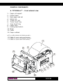
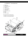
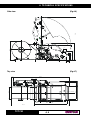
PRINTER COMPONENTS
A. TPTCM60-xC(1) – Front external view
1- Paper roll support
2- Printer frame
3- Near paper end led
4- Status led
5- “Power on” led
6- “Form Feed” Key
7- “Line Feed” Key
8- Paper input
9- Printing mechanism
10- Motor
11- Cutter
12- Paper outfeed
(1) The x suffix indicates the following models :
- TPTCM60-SC (version with serial interface)
- TPTCM60-PC (version with parallel interface)
- TPTCM60-UC (version with USB interface)

TPTCM
8
11
9
1
2
10
13
12
7
6
3
4
5
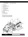
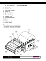
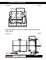
B. TPTCM60-xE (2) – Front external view
1- Paper roll
2- Printer frame
3- Near paper end led
4- Status led
5- “Power on” led
6- “Form Feed” key
7- “Line Feed” key
8- Paper input
9- Printing mechanism
10- Motor
11- Cutter
12- Dispenser unit
13- Paper outfeed
(2) The x suffix indicates the following models :
- TPTCM60-SE (version with serial interface)
- TPTCM60-PE (version with parallel interface)
- TPTCM60-UE (version with USB interface)

TPTCM
8
11
9
6
3
4
5
1
2
7
10
12
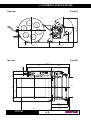
C. TPTCM112-xC(3) - Front external view
1- Paper roll
2- Printer frame
3- Near paper end led
4- Status led
5- “Power on” led
6- “Form Feed” key
7- “Line Feed” key
8- Paper input
9- Printing mechanism
10- Motor
11- Cutter
12- Paper outfeed
(3) The x suffix indicates the following models :
- TPTCM112-SC (version with serial interface)
- TPTCM112-PC (version with parallel interface)
- TPTCM112-UC (version with USB interface)

TPTCM
8
11
9
1
2
7
10
13
12
6
3
4
5
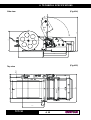
D. TPTCM112-xE (4) – Front external view
1- Paper roll
2- Printer frame
3- Near paper end led
4- Status led
5- “Power on” led
6- “Form Feed” key
7- “Line Feed” key
8- Ingresso carta
9- Printing mechanism
10- Motor
11- Cutter
12- Dispenser unit
13- Paper outfeed
(4) The x suffix indicates the following models :
- TPTCM112-SE (version with serial interface)
- TPTCM112-PE (version with parallel interface)
- TPTCM112-UE (version with USB interface)

TPTCM
1
2
3
1
2
3
1
2
3
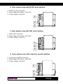
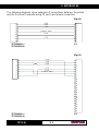
E. Rear external view with RS232 serial interface
1- RS232 serial connector
2- Near paper end sensor connector
3- Power supply connector
F. Rear external view with USB serial interface
1- USB serial connector
2- Near paper end sensor connector
3- Power supply connector
G. Rear external view with Centronics parallel interface
1- Centronics parallel connector
2- Near paper end sensor connector
3- Power supply connector

TABLE OF CONTENTS
TPTCM
i
INTRODUCTION
MANUAL CONTENTS ....................................................................................1
EXPLANATORY NOTES USED IN THIS MANUAL ......................................1
GENERAL SAFETY INFORMATION.............................................................1
UNPACKING THE PRINTER .........................................................................2
PRINTER FEATURES ...................................................................................3
PRINTER DESCRIPTION .............................................................................4
1. INSTALLATION AND USE
1.1 CONNECTIONS................................................................................... 1-1
1.1.1 Power Supply................................................................................. 1-1
1.2 SELF-TEST.......................................................................................... 1-2
1.3 CONFIGURATION ............................................................................... 1-4
1.4 HEXADECIMAL DUMP ........................................................................ 1-5
1.5 MAINTENANCE.................................................................................... 1-6
1.5.1 Changing the paper roll.................................................................. 1-6
2. INTERFACES
2.1 RS232 SERIAL .................................................................................... 2-1
2.2 USB SERIAL INTERFACE .................................................................. 2-3
2.3 CENTRONICS PARALLEL.................................................................. 2-4
3. PRINTER FUNCTIONS
3.1 PRINTING MODES.............................................................................. 3-1
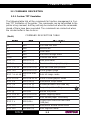
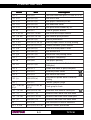
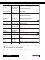
3.2 CONTROL CHARACTERS ................................................................. 3-2
3.2.1 Custom TPT emulation ................................................................. 3-2
3.2.2 ESC/POS emulation ..................................................................... 3-2
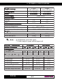
4. TECHNICAL SPECIFICATIONS
4.1 TECHNICAL SPECIFICATIONS......................................................... 4-1
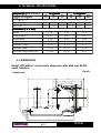
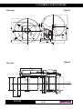
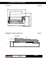
4.2 DIMENSIONS....................................................................................... 4-3

TABLE OF CONTENTS
TPTCM ii
5. CHARACTER SETS
5.1 CHARACTER SETS ............................................................................ 5-1
APPENDIX A - ACCESSORIES AND SPARE PARTS
A.1 ACCESSORIES................................................................................... A-1
A.1.1 Power supply for TPTCM60x model printers................................ A-1
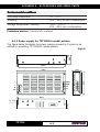
A.1.2 Power supply for TPTCM112x model printers.............................. A-2
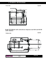
A.1.3 Plastic dispenser ........................................................................... A-4
A.1.4 Positionable roll holder support..................................................... A-6
A.2 SUPPLIES .........................................................................................A-10

INTRODUCTION
TPTCM
1
MANUAL CONTENTS
In addition to the Introduction which includes a description of the explanatory
notes used in the manual, general safety information, how to unpack the
printer and a brief description of the printer including its basic features, this
manual is organized as follows:
Chapter 1: Contains the information required for correct printer installation
and its proper use
Chapter 2: Contains information on interface specifications
Chapter 3: Contains a description of the printer command set
Chapter 4: Contains Technical Specifications of the printer
Chapter 5: Contains the character sets (fonts) used by the printer
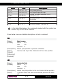
EXPLANATORY NOTES USED IN THIS MANUAL
N.B.
Gives important information or suggestions relative to the use of the
printer.
WARNING
Information marked with this symbol must be carefully followed to
guard against damaging the printer.
DANGER
Information marked with this symbol must be carefully followed to
guard against operator injury or damage.
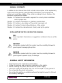
GENERAL SAFETY INFORMATION
•Read and keep the instructions which follow.
•Follow all warnings and instructions indicated on the printer.
•Before cleaning the printer, disconnect the power supply.
•Clean the printer with a damp cloth. Do not use liquid or spray products.
•Do not operate the printer near water.
•Do not use the printer on unstable surfaces that might cause it to fall and
be seriously damaged.

INTRODUCTION
TPTCM 2
•Only use the printer on hard surfaces and in environments that guarantee
proper ventilation.
•Make sure the printer is placed in such a way as to avoid damage to its
wiring.
•Use the type of electrical power supply indicated on the printer label. If in
doubt, contact your retailer.
•Do not block the ventilation openings.
•Do not introduce foreign objects of any kind into the printer as this could
cause a short circuit or damage parts that could jeopardize printer
functioning.
•Do not spill liquids onto the printer.
•Do not carry out technical operations on the printer, with the exception of
the scheduled maintenance procedures specifically indicated in the user
manual.
•Disconnect the printer from the electricity supply and have it repaired by a
specialized technician when:
A. The feed connector has been damaged.
B. Liquid has seeped inside the printer.
C. The printer has been exposed to rain or water.
D. The printer is not functioning normally despite the fact that all
instructions in the users manual have been followed.
E. The printer has been dropped and its outer casing damaged.
F. Printer performance is poor.
G. The printer is not functioning.
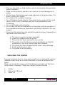
UNPACKING THE PRINTER
Remove the printer from its carton being careful not to damage the packing
material so that it may be re-used if the printer is to be transported in the
future.
Make sure that all the components listed below are present and that there
are no signs of damage. If there are, contact Customer Service.
1. Printer
2. Manual (or CD-Rom)
3. Paper roll

INTRODUCTION
TPTCM
3
PRINTER FEATURES
SYMBOL LEGEND:
The symbol @ indicates the TPTCM60x
The symbol A indicates the TPTCM112x
The TPTCM printer series is comprised of printers designed to emit high-
resolution thermal-printed tickets ideal for use in information and multimedia
kiosks, self-service machines, no-queue systems, parking areas, gaming
machines and toll receipt machines.
Two ticket presentation systems are available on the TPTCM series:
- Motor-driven dispenser with sensors on the dispenser that holds the ticket
while it is being printed and then delivers it once it has been cut. Ideal for
those systems requiring a variable-length ticket.
- Static presenter: Delivers and manages ticket presence using a paper
sensor in outfeed. Ideal for those systems in which printed ticket length is
fixed.
The TPTCM series offers a wide range of options in addition to normal print
features:
•High speed printing: @ 140mm/sec,A 120 mm/sec.
•ESC/POS and CUSTOM TPT emulation.
•Bar code UPC-A. UPC-E, EAN13, EAN8, CODE39, ITF, CODABAR,
CODE93, CODE128 and CODE32.
•6 standard and international character set fonts.
•Completely- or partially-programmable fonts.
•Double width/height, quadruple width/height, expanded, italic, rotated
90°, 180° and 270°.
•Receive buffer: 16Kbytes.
•Definition of function macros for automatic operation repetition.
•Internal programmable counter.
•Graphic print mode.
•Print density.
•3 programmable logos: @ (448 x 585 dots) or A (832 x 314 dots).
•Paper cutter.
•Positionable paper roll holder.
•Plastic paper outfeed slot.

INTRODUCTION
TPTCM 4
2
1
3
5
9
6
4
8
7
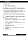
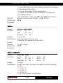
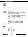
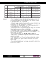
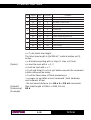
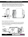
PRINTER DESCRIPTION
The TPTCM printers (fig.1) are comprised of a metal frame (1), paper roll
holder (2), printing mechanism (3) and cutter (4).
The following keys are located on the control panel: FORM FEED (5), LINE
FEED (6), “Power On” LED (7), Paper Low LED (8) and “Status” LED (9).
•When the LINE FEED (6) key is pressed, the printer advances the
paper so that it may be inserted manually in the printing mechanism.
During power-up, if the LINE FEED key is held down, the printer will
perform the FONT TEST routine.
•If the FORM FEED (5) key is enabled, when it is pressed the printer
advances the paper the number of increments programmed in the
Eeprom.
(Fig.1)

INTRODUCTION
TPTCM
5
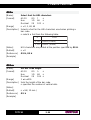
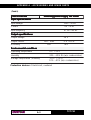
(Tab.1)
f the FORM FEED key is not enabled and the printer is in Custom
Emulation mode, when the key is pressed, the code 12 (HEX 0C) is
transmitted on the RS232 serial line. This function may be modified by
the ESC = software command (see section on software commands).
•During power-up, if both keys are held down, the printer enters the print
setup routine. Following the print-out of the setup report, the printer
remains in standby until a key is pressed or signals arrive from the serial
port; each 10 characters it prints out hexadecimal and ASCII codes (if
the characters are underlined, the receive buffer is full); see Receive
buffer hexidecimal print-out
•The “Power On” LED (green) indicates that the printer is on.
•The Paper Low LED (red) indicates that the paper is about to run out.
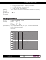
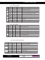
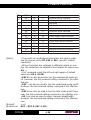
•The “Status” LED (yellow) indicates printer status; the check is made
on-line. Given in the table below are the various LED signals and the
corresponding printer status.
sutatsDELsutatsDEL sutatsDEL sutatsDELsutatsDELnoitpircseDnoitpircseD noitpircseD noitpircseDnoitpircseD
ydaetSNOretnirP- noitcnuflamon
gniknilbdipaRgnitaehrevO
gniknilbwolS( doirepdednetxeroftil) egassem"repaPoN"
gniknilbwolS( )doireptrohsroftilsdrawpudenrutdaeH
ffosniameRnoitcnuflamretnirP

1. INSTALLATION AND USE
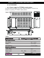
TPTCM11-
Pin 1
J5
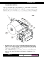
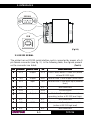
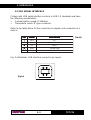
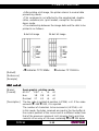
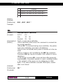
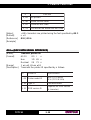
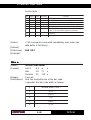
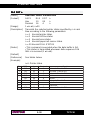
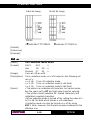
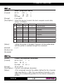
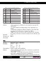
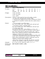
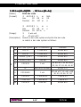
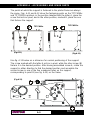
1.1 CONNECTIONS
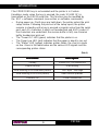
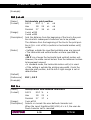
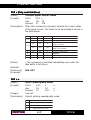
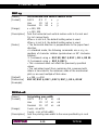
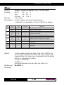
1.1.1 Power supply
For the power supply, the printer is equipped with a male, 90° mobile screw
(pitch 5.08mm) terminal (J5). The signals on the power suppy connector pins
are as follows:
WARNING:
Respect power supply polarity.
.onniP.onniP .onniP .onniP.onniPlangiSlangiS langiS langiSlangiS
11
1
11 DNG
22
2
22 ylppusrewopccV42
(Fig.1.1)
(Tab.1.1)

1. INSTALLATION AND USE
TPTCM 21-
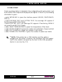
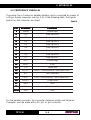
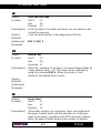
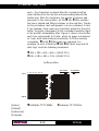
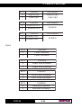
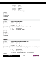
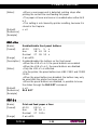
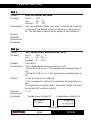
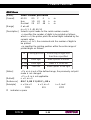
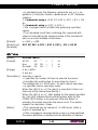
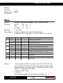
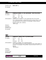
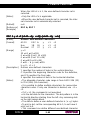
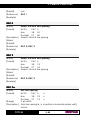
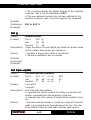
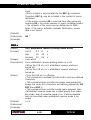
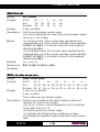
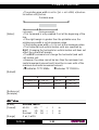
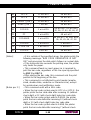
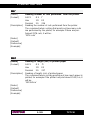
1.2 SELF-TEST
Printer operating status is indicated in the configuration print-out in which, next
to the name of the components displayed (see figures 1.2 and 1.3), the following
information is given:
• under INTERFACE is given the interface present (RS232, CENTRONICS,
USB (1) ).
• under EEPROM TEST and CUTTER TEST, the message OK appears if
functioning and NOT OK if faulty.
• under EJECTER TEST, the message OK appears if functioning, NONE if
not present and NOT OK if faulty.
• under HEAD TEMPERATURE is given the temperature of the head.
• under PAPER PRINTED is given the number of centimeters of paper printed.
• under CUT COUNTER is given the number of cuts made.
• under POWER ON COUNTER is given the number of power-ups made.
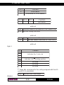
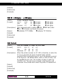
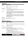
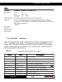
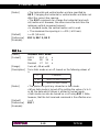
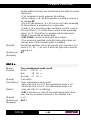
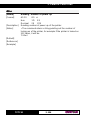
(1) NOTE: If the printer has a USB interface and the cable is
plugged into the printer connector, the message USB will appear
next to the address assigned by the Host to the USB peripheral
device in use (see fig. 1.3).

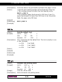
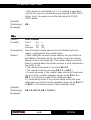
1. INSTALLATION AND USE
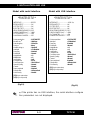
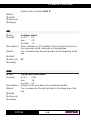
TPTCM31-
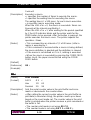
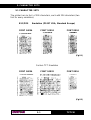
Model with serial interface Model with USB interface
(2) If the printer has an USB interface, the serial interface configura
tion parameters are not displayed.
(Fig.1.2)
* PRINTER SETUP *
INTERFACE............................: RS232
EEPROM TEST...................... : OK
CUTTER TEST...................... : OK
EJECTER TEST..................... : OK
HEAD TEMPERATURE [°C].: 22.5
PAPER PRINTED [cm]..........: 9860
CUT COUNTER.....................: 604
POWER ON COUNTER........:135
Printer emulation : CUSTOM TPT
Baud Rate (2) : 9600 bps
Data length (2) : 8 bits/chr
Parity (2) : None
Handshaking (2) : Xon/Xoff
Autofeed : CR disabled
Panel key : Enabled
Print Mode : Normal
Height Mode : x 1
Width Mode : x 1
Justification : Left
Character set : U.S.A.
Font Dimension : 16x24 28 col
Speed / Quality : Normal
Current : Normal
Paper autoload : Enabled
Reset buffer : At Paper End
Print Density : Normal
[FF] Key to enter setup
[LF] Key to skip setup
* PRINTER SETUP *
INTERFACE............................: USB : 2 (1)
EEPROM TEST...................... : OK
CUTTER TEST...................... : OK
EJECTER TEST..................... : OK
HEAD TEMPERATURE [°C].: 22.5
PAPER PRINTED [cm]..........: 9860
CUT COUNTER.....................: 604
POWER ON COUNTER........:135
Printer emulation : CUSTOM TPT
Autofeed : CR disabled
Panel key : Enabled
Print Mode : Normal
Height Mode : x 1
Width Mode : x 1
Justification : Left
Character set : U.S.A.
Font Dimension : 16x24 28 col
Speed / Quality : Normal
Current : Normal
Paper autoload : Enabled
Reset buffer : At Paper End
Print Density : Normal
[FF] Key to enter setup
[LF] Key to skip setup
(Fig.1.3)

1. INSTALLATION AND USE
TPTCM 41-
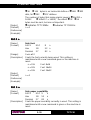
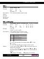
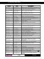
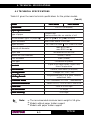
1.3 CONFIGURATION
This printer permits the configuration of default parameters. The printer’s
configurable parameters are:
•Printer emulation: ESC/POS, CUSTOM TPT D.
If a serial interface is present:
•Baud Rate: 57600, 38400, 19200, 9600 D, 4800, 2400, 1200.
•Data length: 7, 8 bits/char D.
•Parity: None D, even or odd.
•Handshaking: XON/XOFF D or Hardware.
If a parallel interface is present:
•Select line: Select D, Ticket Present, Paper Low.
•Fault line: Error D, Ticket Present, Paper Low.
•Autofeed: CR deactivated D or CR activated.
•Panel keys: Activated D or deactivated.
•Print mode: Normal D or Reverse.
•Height mode: x1 D , x2 or x4.
•Width mode: x1 D, x2 or x4.
•Justification: Left D, Centered or Right.
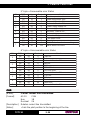
With ESC/POS
emulation:
•Char/line: @A=32 / B=42 columnsD or A=42 / B=56 columns
AA=58 / B=82 columnsD or A=82 / B=104 columns
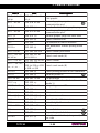
With CUSTOM TPT emulation:
•Font Size:
d.loc81.loc81 .loc81 .loc81.loc81.loc82.loc82 .loc82 .loc82.loc82
.l
oc65
.l
oc65
.l
oc65
.l
oc65
.l
oc65
23x4242x6161x8 e.loc43.loc43 .loc43 .loc43.loc43.loc25.loc25 .loc25 .loc25.loc25
.l
oc401
.l
oc401
.l
oc401
.l
oc401
.l
oc401
23x4242x6161x8
•Speed/Quality: Normal D, Draft or High Quality.
•Paper Autoload: Deactivated D or Activated.
•Reset buffer: Not implemented, At paper end D.
•Print density: Normal D, Light, Very light, Dark, Very dark, Double copy.

1. INSTALLATION AND USE
TPTCM51-
General notes:
1) The parameters marked with the symbol D are the default values.
2) The symbol @ indicates the TPTCM60x
3) The symbol A indicates the TPTCM112x
4) Settings remain active even after the printer has been turned off.
The settings made are stored in EEPROM (nonvolative memory).
During power-up, if both the LINE FEED and FORM FEED keys are held
down, the printer enters configuration mode and prints-out the setup report; it
will remain in standby until a key is pressed or characters are received
through the communication port (see Hexadecimal dump).
When the LINE FEED key is pressed, the printer skips the setup mode and
terminates the Hexadecimal dump function.
When the FORM FEED key is pressed, the printer enters the parameter
entry mode.
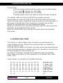
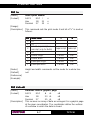
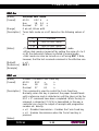
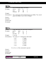
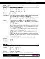
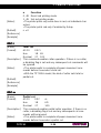
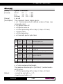
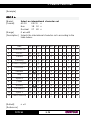
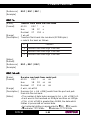
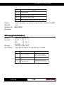
1.4 HEXADECIMAL DUMP
This function is used to diagnose the characters received through the
communication port; the characters are printed out both as hexadecimal
codes and ASCII codes.
Once the self-test routine has finished, the printer enters Hexadecimal Dump
mode. The printer remains in standby until a key is pressed or characters are
received through the communication port.
For every 10 characters received, the hexadecimal and corresponding
ASCII codes are printed out (if the characters are underlined, the receive
buffer is full).
Shown below is an example of a Hexadecimal Dump:
48 65 78 61 64 65 63 69 6D 61 Hexadecima
6C 20 64 75 6D 70 20 66 75 6E l dump fun
63 74 69 6F 6E 20 30 31 32 33 ction 0123
34 35 36 37 38 39 61 62 63 64 456789abcd
65 66 67 68 69 6A 6B 6C 6D 6E efghijklmn
6F 70 71 72 73 74 75 76 77 78 opqrstuvwx
79 7A yz

1. INSTALLATION AND USE
TPTCM 61-
3
1
2
4
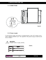
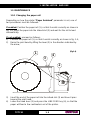
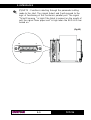
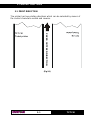
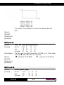
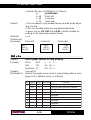
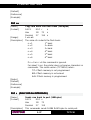
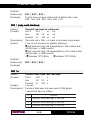
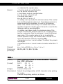
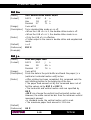
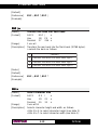
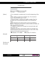
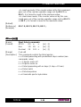
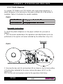
1.5 MAINTENANCE
1.5.1 Changing the paper roll
Depending on how the printer “Paper Autoload” parameter is set, one of
two procedures must be followed:
If enabled: Position the paper roll (1), so that it unrolls correctly as shown in
fig. 1.4; insert the paper into the infeed slot (3) and wait for the roll to load
automatically.
If not enabled, proceed as follows:
1) Position the paper roll (1), so that it unrolls correctly as shown in fig. 1.4;
2) Raise the print head by lifting the lever (2) in the direction indicated by
the arrow;
3) Insert the end of the paper roll into the infeed slot (3) and have it pass
beyond the print head;
4) Lower the head lever (3) and press the LINE FEED key (4), so that the
paper will feed a few centimeters out of the printer.
(Fig.1.4)
Page is loading ...
Page is loading ...
Page is loading ...
Page is loading ...
Page is loading ...
Page is loading ...
Page is loading ...
Page is loading ...
Page is loading ...
Page is loading ...
Page is loading ...
Page is loading ...
Page is loading ...
Page is loading ...
Page is loading ...
Page is loading ...
Page is loading ...
Page is loading ...
Page is loading ...
Page is loading ...
Page is loading ...
Page is loading ...
Page is loading ...
Page is loading ...
Page is loading ...
Page is loading ...
Page is loading ...
Page is loading ...
Page is loading ...
Page is loading ...
Page is loading ...
Page is loading ...
Page is loading ...
Page is loading ...
Page is loading ...
Page is loading ...
Page is loading ...
Page is loading ...
Page is loading ...
Page is loading ...
Page is loading ...
Page is loading ...
Page is loading ...
Page is loading ...
Page is loading ...
Page is loading ...
Page is loading ...
Page is loading ...
Page is loading ...
Page is loading ...
Page is loading ...
Page is loading ...
Page is loading ...
Page is loading ...
Page is loading ...
Page is loading ...
Page is loading ...
Page is loading ...
Page is loading ...
Page is loading ...
Page is loading ...
Page is loading ...
Page is loading ...
Page is loading ...
Page is loading ...
Page is loading ...
Page is loading ...
Page is loading ...
Page is loading ...
Page is loading ...
Page is loading ...
Page is loading ...
Page is loading ...
Page is loading ...
Page is loading ...
Page is loading ...
Page is loading ...
Page is loading ...
Page is loading ...
Page is loading ...
Page is loading ...
Page is loading ...
Page is loading ...
Page is loading ...
Page is loading ...
Page is loading ...
Page is loading ...
Page is loading ...
Page is loading ...
Page is loading ...
Page is loading ...
Page is loading ...
Page is loading ...
Page is loading ...
Page is loading ...
Page is loading ...
Page is loading ...
Page is loading ...
Page is loading ...
Page is loading ...
Page is loading ...
Page is loading ...
Page is loading ...
Page is loading ...
Page is loading ...
Page is loading ...
Page is loading ...
Page is loading ...
Page is loading ...
Page is loading ...
Page is loading ...
Page is loading ...
Page is loading ...
Page is loading ...
Page is loading ...
Page is loading ...
Page is loading ...
Page is loading ...
Page is loading ...
Page is loading ...
Page is loading ...
Page is loading ...
Page is loading ...
Page is loading ...
Page is loading ...
Page is loading ...
Page is loading ...
Page is loading ...
Page is loading ...
Page is loading ...
Page is loading ...
Page is loading ...
Page is loading ...
Page is loading ...
-
 1
1
-
 2
2
-
 3
3
-
 4
4
-
 5
5
-
 6
6
-
 7
7
-
 8
8
-
 9
9
-
 10
10
-
 11
11
-
 12
12
-
 13
13
-
 14
14
-
 15
15
-
 16
16
-
 17
17
-
 18
18
-
 19
19
-
 20
20
-
 21
21
-
 22
22
-
 23
23
-
 24
24
-
 25
25
-
 26
26
-
 27
27
-
 28
28
-
 29
29
-
 30
30
-
 31
31
-
 32
32
-
 33
33
-
 34
34
-
 35
35
-
 36
36
-
 37
37
-
 38
38
-
 39
39
-
 40
40
-
 41
41
-
 42
42
-
 43
43
-
 44
44
-
 45
45
-
 46
46
-
 47
47
-
 48
48
-
 49
49
-
 50
50
-
 51
51
-
 52
52
-
 53
53
-
 54
54
-
 55
55
-
 56
56
-
 57
57
-
 58
58
-
 59
59
-
 60
60
-
 61
61
-
 62
62
-
 63
63
-
 64
64
-
 65
65
-
 66
66
-
 67
67
-
 68
68
-
 69
69
-
 70
70
-
 71
71
-
 72
72
-
 73
73
-
 74
74
-
 75
75
-
 76
76
-
 77
77
-
 78
78
-
 79
79
-
 80
80
-
 81
81
-
 82
82
-
 83
83
-
 84
84
-
 85
85
-
 86
86
-
 87
87
-
 88
88
-
 89
89
-
 90
90
-
 91
91
-
 92
92
-
 93
93
-
 94
94
-
 95
95
-
 96
96
-
 97
97
-
 98
98
-
 99
99
-
 100
100
-
 101
101
-
 102
102
-
 103
103
-
 104
104
-
 105
105
-
 106
106
-
 107
107
-
 108
108
-
 109
109
-
 110
110
-
 111
111
-
 112
112
-
 113
113
-
 114
114
-
 115
115
-
 116
116
-
 117
117
-
 118
118
-
 119
119
-
 120
120
-
 121
121
-
 122
122
-
 123
123
-
 124
124
-
 125
125
-
 126
126
-
 127
127
-
 128
128
-
 129
129
-
 130
130
-
 131
131
-
 132
132
-
 133
133
-
 134
134
-
 135
135
-
 136
136
-
 137
137
-
 138
138
-
 139
139
-
 140
140
-
 141
141
-
 142
142
-
 143
143
-
 144
144
-
 145
145
-
 146
146
-
 147
147
-
 148
148
-
 149
149
-
 150
150
-
 151
151
-
 152
152
-
 153
153
-
 154
154


Custom Audio Electronics TPTCM60-PC User manual
- Category
- Print & Scan
- Type
- User manual
- This manual is also suitable for
Ask a question and I''ll find the answer in the document
Finding information in a document is now easier with AI
Related papers
-
Custom Audio Electronics TPTCM User manual
-
CUSTOM FH190-40-RS232-5V User manual
-
-
-
-
 CUSTOM VKP80II-UE-SX User manual
-
-
 CUSTOM TL60 User manual
-
-


Other documents
-
 Custom Engineering KPM 216H II User manual
-
 SPRT SP-RME3 Owner's manual
-
 SPRT SP-EU58III Owner's manual
-
 Infinite Peripherals KPM-210 User manual
-
Argox X-3200 User manual
-
Argox Argox X Series User manual
-
 Blue Bamboo P25i Specification
-
Fenix EPC1200 Operating instructions
-
-
Zebra TTP Owner's manual


