Page is loading ...

Thermo Scientific
Dilutor Module for TriPlus
RSH
Instruction Manual
Additional section of the TriPlus RSH User Guide and
Hardware Manual
31709661 Revision A December 2015

© 2015 Thermo Fisher Scientific Inc. All rights reserved.
TriPlus RSH, TRACE 1300, TRACE 1310, TRACE GC Ultra and FOCUS GC are trademarks of Thermo
Fisher Scientific Inc., and its subsidiaries.
Published by Thermo Fisher Scientific S.p.A., Strada Rivoltana 20090 Rodano-Milan, Italy
Tel: +39 02 95059303; Fax: +39 02 95059388
Thermo Fisher Scientific Inc. provides this document to its customers with a product purchase to use in the
product operation. This document is copyright protected and any reproduction of the whole or any part of this
document is strictly prohibited, except with the written authorization of Thermo Fisher Scientific Inc.
The contents of this document are subject to change without notice. All technical information in this
document is for reference purposes only. System configurations and specifications in this document supersede
all previous information received by the purchaser.
This document is not part of any sales contract between Thermo Fisher Scientific Inc. and a purchaser. This
document shall in no way govern or modify any Terms and Conditions of Sale, which Terms and Conditions of
Sale shall govern all conflicting information between the two documents.
Release history: Revision A, December 2015 “Original Instructions”
For Research Use Only. Not for use in diagnostic procedures.

Thermo Scientific Dilutor Module for TriPlus RSH Instruction Manual iii
C
Chapter 1 Dilutor Module for TriPlus RSH . . . . . . . . . . . . . . . . . . . . . . . . . . . . . . . . . . . . . . . . . .1
Safety Alerts, Important Information and Warnings . . . . . . . . . . . . . . . . . . . . . . 2
Module Description . . . . . . . . . . . . . . . . . . . . . . . . . . . . . . . . . . . . . . . . . . . . . . 2
Naming Conventions . . . . . . . . . . . . . . . . . . . . . . . . . . . . . . . . . . . . . . . . . . . . . 2
Dilutor Module Specifications. . . . . . . . . . . . . . . . . . . . . . . . . . . . . . . . . . . . . . . 3
Hardware and Software Requirements. . . . . . . . . . . . . . . . . . . . . . . . . . . . . . . . . 4
Unpacking the Components . . . . . . . . . . . . . . . . . . . . . . . . . . . . . . . . . . . . . . . . 5
Getting Started . . . . . . . . . . . . . . . . . . . . . . . . . . . . . . . . . . . . . . . . . . . . . . . . . . 6
Installing the Dilutor Valve . . . . . . . . . . . . . . . . . . . . . . . . . . . . . . . . . . . . . . . . . 6
Installing the Dilutor Syringe . . . . . . . . . . . . . . . . . . . . . . . . . . . . . . . . . . . . . . . 8
Installing the Dilutor Syringe Module . . . . . . . . . . . . . . . . . . . . . . . . . . . . . . . . . 9
Installing the Dilutor Tool . . . . . . . . . . . . . . . . . . . . . . . . . . . . . . . . . . . . . . . . 11
Connecting the Transfer Tubing . . . . . . . . . . . . . . . . . . . . . . . . . . . . . . . . . . 12
Electrical Connections. . . . . . . . . . . . . . . . . . . . . . . . . . . . . . . . . . . . . . . . . . . . 15
Setting Up the Dilutor Syringe Module. . . . . . . . . . . . . . . . . . . . . . . . . . . . . . . 15
Dilutor Module Parameters . . . . . . . . . . . . . . . . . . . . . . . . . . . . . . . . . . . . . . 18
Options Menu Items for Dilutor (x) . . . . . . . . . . . . . . . . . . . . . . . . . . . . . . . 18
Setting Up the Dilutor Tool . . . . . . . . . . . . . . . . . . . . . . . . . . . . . . . . . . . . . . . 20
Dilutor Tool Parameters . . . . . . . . . . . . . . . . . . . . . . . . . . . . . . . . . . . . . . . . 22
Options Menu Items for DIL (x). . . . . . . . . . . . . . . . . . . . . . . . . . . . . . . . . . 23
Calibrating the Dilutor Tool . . . . . . . . . . . . . . . . . . . . . . . . . . . . . . . . . . . . . . . 23
Routine Operation and Limitations. . . . . . . . . . . . . . . . . . . . . . . . . . . . . . . . . . 25
Maintenance and Troubleshooting . . . . . . . . . . . . . . . . . . . . . . . . . . . . . . . . . . 26
Contents


Thermo Scientific Dilutor Module for TriPlus RSH Instruction Manual 1
Dilutor Module for TriPlus RSH
This manual is an additional section of the TriPlus RSH User Guide (P/N 31709620) and
TriPlus RSH Hardware Manual (PN 31709640). It contains information for installing,
operating, and maintaining the Dilutor module.
Contents
•Safety Alerts, Important Information and Warnings
•Module Description
•Naming Conventions
•Dilutor Module Specifications
•Hardware and Software Requirements
•Unpacking the Components
•Getting Started
•Installing the Dilutor Valve
•Installing the Dilutor Syringe
•Installing the Dilutor Syringe Module
•Installing the Dilutor Tool
•Electrical Connections
•“Setting Up the Dilutor Syringe Module” on page 15
•“Setting Up the Dilutor Tool” on page 20
•“Calibrating the Dilutor Tool” on page 23
•“Routine Operation and Limitations” on page 25
•“Maintenance and Troubleshooting” on page 26
Note Items highlighted in green are only visible in the access level Extended User.

Dilutor Module for TriPlus RSH
Safety Alerts, Important Information and Warnings
2 Dilutor Module for TriPlus RSH Instruction Manual Thermo Scientific
Safety Alerts, Important Information and Warnings
About the safety alerts, the important information and the series of warning refer to the
chapter Preface of the TriPlus RSH User Guide and TriPl us R SH Hardware Ma nua l.
Module Description
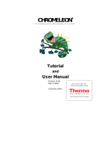
The Dilutor Module is an optional device for the TriPlus RSH System. Its main purpose is
typically solvent handling, such as adding a solvent for dilution, a reagent for derivatization,
spiking with an internal standard, and so on. Another widely used application is sampling an
exact volume of an aliquot and pipetting it into another vessel for further processing.
See Figure 1.
Figure 1. Dilutor Module
Naming Conventions
Naming conventions for the Dilutor Module and its parts are listed below:
•Dilutor Module — Describes the entire assembly of the Module.
•Dilutor Syringe Module — Active module carrying the Dilutor Syringe and the Dilutor
Valve.
•Dilutor Tool — Describes the tool itself as part of the Dilutor Module.
•Dilutor Valve — It is placed on the Dilutor Syringe Module and one of its ports is
connected to the Dilutor Syringe. Two types are available:
Two versions are available:
Single Dilutor
With a 3-port valve for 1/4-in.-28 fittings
Multi Dilutor
With a 7-port (6+) ceramic valve for 1/4-in.-28
fittings

Dilutor Module for TriPlus RSH
Dilutor Module Specifications
Thermo Scientific Dilutor Module for TriPlus RSH Instruction Manual 3
– 3-Port (3P) PTFE Valve
– 7-Port (6+) Ceramic Valve
•Mounting Bracket — Fixes the Dilutor Module to the X-Axis of the TriPlus RSH.
Contains two holders for the Guiding Wire.
•Solvent Reservoir Kit — Consists of one reservoir bottle (1 L) with tubing (PFA) and one
glass frit with a pore size of 40 μm.
•Tr a n sf e r Tu b i n g K i t — Connects the Dilutor Module and Dilutor Tool. Consists of the
PFA Tubing, the Guiding Wire and connection fittings.
•Guiding Wire — The Wire integrated into the Transfer Tubing.
Dilutor Module Specifications
The specifications of the Dilutor Module are:
•Dilutor Module — Single Dilutor or Multi Dilutor
•Dilutor Valve — 3-port (3P) valve for ¼-in.-28 fittings for Single Dilutor;
7-port (6+) Ceramic (Alumina) valve for ¼-in.-28 fittings for Multi Dilutor
•Maximum Permissible Pressure — 3 bar (300 kPa; 43.5 psig)
•Dilutor Syringe — 1 mL, Scale 60 mm; Optional 0.1 mL, 5 mL, 10 mL
•Tr a n sf e r Tu b i n g — PFA tubing ID 0.787 mm (1/32”) / OD 1.58 mm (1/16”) Including
Connection Fittings and Guiding Wire Length of transfer tubing: 1530 mm
•Needle — Gauge 22, Pst 3, Length 51 mm; Optional Gauge 23, Pst AS, Length 51 mm
•Solvent Reservoir Kit (1 piece for Single Dilutor; 5 pieces for Multi Dilutor) — 1000 mL
borosilicate glass including:
– Glass Filter, 40 μm pore size (1000-SV)
– Aspiration Tubing (PFA)
•Wetted Parts — Tubing from Reservoir Bottle to Dilutor Syringe Module.
Tu b i n g : P FA
Frit: Glass Filter
Dilutor Syringe Module:
– Syringe: Borosilicate Glass
Valve 3-port: PTFE / Kel-F
Valve 7-port: Ceramic (Alumina)
Transfer tubing from Pump to LCP Tool:

Dilutor Module for TriPlus RSH
Hardware and Software Requirements
4 Dilutor Module for TriPlus RSH Instruction Manual Thermo Scientific
–Tubing: PFA
•Electrical Connectors — Two BUS connectors for daisy chaining; M12, 4 position,
male, reserved for future use.
•Firmware — Version 2.1.0 or higher
The Dilutor Module dimensions, weights, operating and environmental requirements are
detailed in Tab le 1 and Table 2.
Hardware and Software Requirements
Observe the compatibility between the Device Firmware and the RSH Firmware. The Dilutor
Module used for the TriPlus RSH System is an active module which requires its own specific
Device Firmware.
Table 1. Dilutor - Dimensions and Mass
Length Dimension in mm (inches)
Width 115 (4.52);
175 (6.89) including cable connectors
Depth 260 (10.24)
Height 430 (16.93)
550 (21.65) including transfer tubing
Mass Dimension in kg (lbs)
Dilutor Syringe Module 1.31 (2.89)
Mounting Bracket 0.220 (0.49)
Associated Cable 0.15 (0.33)
Solvent Reservoir Kit Aspiration Kit: 0.06 (0.13)
Reservoir Bottle 1000 mL: 0.58 (1.28)
Total Weight of Single Dilutor 2.32 (5.11)
Total Weight of Multi Dilutor 4.88 (10.76)
Table 2. Dilutor - Operating and Environmental Requirements
Length Dimension in mm (inches)
Operating Temperature Range 4 to 40 °C
Maximum Relative Humidity 80%, non-condensing
Bench Space Consider bench space for the Wash Solvent
reservoir bottles, size 1000 mL (or as
required by customer)
Altitude Limitations 3000 meters above sea level

Dilutor Module for TriPlus RSH
Unpacking the Components
Thermo Scientific Dilutor Module for TriPlus RSH Instruction Manual 5
The Device Firmware is part of the archive file with the extension *.pack. The TriPlus RSH
System already has the necessary software packages pre-loaded when shipped from the factory.
The Dilutor Module requires the RSH Firmware 2.1.0 or higher.
Unpacking the Components
The Dilutor Module is shipped in a dedicated box separated from the TriPlus RSH system.
The box also includes the Solvent Reservoir Kit(s), each consisting of a 1000 mL glass bottle,
a glass frit, and the corresponding Tubing Kit.
The components of Single Dilutor and Multi Dilutor contained into the relevant shipping
box are respectively detailed in Tab le 3 and Tab le 4.
Table 3. Single Dilutor Components
Component Quantity
Dilutor Syringe Module 1
Syringe for Dilutor Syringe Module 1 mL, Scale 60 mm (pre-mounted) 1
Dilutor Valve 3-Port (1/4-28-in. Fitting) 1 Pre-mounted
Mounting Bracket 1
Dilutor Tool 1
Solvent Reservoir Kit containing:
– 1 x Glass Bottle 1000 mL
1 x Aspiration Tubing Kit, consisting of:
–Tubing (PFA)
– Glass Frit 40 μm pore size
– Nut with feed-through holes
1
Transfer Tubing Kit for Dilutor (1/16-in.) 1
Needle Gauge 22 Pst 3 (for syringes 5 μL – 100 μL) (Set of 3) 3 (1 pre-mounted)
Bus Daisy Chain Cable, length 850 mm 1
Table 4. Multi Dilutor Components (Sheet 1 of 2)
Component Quantity
Dilutor Syringe Module 1
Syringe for Dilutor Syringe Module 1 mL, Scale 60 mm
(pre-mounted)
1
Dilutor Valve 7-Port ceramic (1/4-28-in. -Fitting) 1

Dilutor Module for TriPlus RSH
Getting Started
6 Dilutor Module for TriPlus RSH Instruction Manual Thermo Scientific
Getting Started
For properly installing the Dilutor Module see the following sections:
•“Installing the Dilutor Valve” on page 6
•“Installing the Dilutor Syringe” on page 8
•“Installing the Dilutor Syringe Module” on page 9
•“Installing the Dilutor Tool” on page 11
Installing the Dilutor Valve
The valve is pre-mounted to the Dilutor Syringe Module. If for any reason it is necessary to
change the valve, see the following procedures:
•“To install the 3-port valve” on page 6
•“To install the 7-port valve” on page 7
To install the 3-port valve
The Single Dilutor is equipped with a 3-port valve for enabling the handling of one
solvent/reagent. A port is reserved for the syringe and another one for the tool. The 3-port
valve is fixed to the valve drive of the Dilutor using the two provided screws. The valve
coupling of the valve drive has one flat side, ensuring the correct installation of the valve.
Mounting bracket 1
Dilutor Tool 1
Solvent Reservoir Kit containing:
– 1 x Glass Bottle 1000 mL
1 x Aspiration Tubing Kit, consisting of:
–Tubing (PFA)
– Glass Frit 40 μm pore size
– Nut with feed-through holes
5
Transfer Tubing Kit for Dilutor (1/16-in.) 1
Needle Gauge 22 Pst 3 for syringes 5 μL – 100 μL 3 (1 pre-mounted)
BUS Daisy Chain Cable, length 850 mm 1
Table 4. Multi Dilutor Components (Sheet 2 of 2)
Component Quantity

Dilutor Module for TriPlus RSH
Installing the Dilutor Valve
Thermo Scientific Dilutor Module for TriPlus RSH Instruction Manual 7
1. Attach the Dilutor Valve to the valve coupling, while slightly turning it to the left or to
the right until it slides completely on the valve coupling. See Figure 2.
2. Turn the valve with the Dilutor Valve coupling until the single port points downwards
and the holes in the housing match with those in the valve. See Figure 2.
3. Fix the valve with the two provided screws. See Figure 2.
Figure 2. 3-Port Valve Installation
To install the 7-port valve
The Multi Dilutor is equipped with a 7-port valve for enabling the handling of up to five
solvents/reagents. A port is reserved for the syringe and another one for the tool. In most cases
it is recommended to specify one of the five free ports as the waste port for flushing the valve.
The 7-port valve is fixed to the valve drive of the Dilutor using the two screws integrated into
the valve. These screws can be accessed from the front of the valve through the small holes
using the provided Allen wrench.
The valve coupling of the valve drive has one flat side, ensuring the correct installation of the
valve.
1. Attach the valve to the valve coupling, while slightly turning it to the left or to the right,
until it slides completely on the valve coupling. See Figure 3.
2. Turn the valve with the valve coupling until the single port points downwards and the
holes in the housing match with those in the valve. See Figure 3.
3. Fix the valve with the two provided screws. See Figure 3.
Valve Drive
Flat Side
CAUTION Do not loosen the two screws on the front of the valve, otherwise the valve may
leak.

Dilutor Module for TriPlus RSH
Installing the Dilutor Syringe
8 Dilutor Module for TriPlus RSH Instruction Manual Thermo Scientific
Figure 3. 7-Port Valve Installation
Installing the Dilutor Syringe
This section provides the instructions for installing the syringe to the Dilutor Syringe Module.
To install the dilutor syringe
1. Screw the syringe clockwise from below into the lower port of the valve. See 1 of Figure 4.
2. Unscrew the screw from the valve drive and pull the plunger of the screw out until the
hole in the plunger matches the hole in the valve drive.
3. Fix the plunger with the screw to the valve drive. See 2 of Figure 4.
Figure 4. Dilutor Syringe Installation
Valve Drive
Flat Side
Note The syringe is pre-mounted to the Dilutor Syringe Module.

Dilutor Module for TriPlus RSH
Installing the Dilutor Syringe Module
Thermo Scientific Dilutor Module for TriPlus RSH Instruction Manual 9
Installing the Dilutor Syringe Module
The Dilutor Syringe Module is attached to the X-Axis using the provided mounting bracket.
Only one mounting bracket can be installed onto a TriPlus RSH system. The mounting
bracket can either hold up to two Dilutor Syringe Modules. See 1 of Figure 5.
For installing only one Dilutor Module use the front mounting position, close to the X-Axis.
See 2 of Figure 5.
Figure 5. Example of Dilutor Mounting Positions
To install the dilutor syringe module on the TriPlus RSH system
1. Install the mounting bracket for the Dilutor on the left side of the X-Axis.
The bracket is installed underneath the side cover of the X-Axis using the two holes at the
back side. See 1 of Figure 6.
The two front holes are reserved for the mounting bracket of the Handheld controller
(terminal).
2. Screw the outer (higher) holder for the Guiding Wire into the bracket. See 2 of Figure 6.
ATTENTION If the Safety Guard is already mounted to the TriPlus RSH system, you must
remove it before installing the mounting bracket for the Dilutor Module.
The Safety Guard bracket on the left side of the TriPlus RSH system will be replaced by
the mounting bracket, so this also must be removed beforehand.

Dilutor Module for TriPlus RSH
Installing the Dilutor Syringe Module
10 Dilutor Module for TriPlus RSH Instruction Manual Thermo Scientific
Figure 6. Mounting Bracket Installation
3. Attach the Safety Guard to the mounting bracket and fix it with the two screws provided.
The Safety Guard Bracket is used on the right side of the X-Axis. See Figure 7.
Figure 7. Installation of the Safety Guard to the Mounting Bracket
Safety Guard Bracket

Dilutor Module for TriPlus RSH
Installing the Dilutor Tool
Thermo Scientific Dilutor Module for TriPlus RSH Instruction Manual 11
4. Install the Dilutor Syringe Module to the front position of the mounting bracket, closer
to the X-Axis, and fix it using the two screws provided. See Figure 8.
Figure 8. Installation of the Dilutor Syringe Module to the Mounting Bracket
Installing the Dilutor Tool
The front or back mounting position of the Dilutor Syringe Module on the mounting bracket
corresponds to the position of the Dilutor Tool in the ATC Station.
If only one Dilutor is added to the TriPlus RSH system, the Dilutor Syringe Module must be
installed on the front position, of the mounting bracket, close to the X-Axis.
The corresponding Dilutor Tool is set to Slot 1 of the ATC Station. The Guiding Wire is
fixed to the lower holder on the mounting bracket.
Note For installing the Dilutor Tool, the ATC Station must be placed on the outermost
left position of the X-Axis. The left leg of the system must be placed on the right side of
the ATC Station.
It might be useful to connect the ATC Station at the end of a daisy chain – in doing so
only one Bus connector is used and the ATC Station can be placed further left due to the
free right connector.

Dilutor Module for TriPlus RSH
Installing the Dilutor Tool
12 Dilutor Module for TriPlus RSH Instruction Manual Thermo Scientific
If a second Dilutor is added, the second Dilutor Syringe Module must be installed on the
back position of the mounting bracket.
The corresponding tool must be set in Slot 2 of the ATC Station. The Guiding Wire is fixed
to the higher holder on the mounting bracket.
Figure 9 shows the installation of two Dilutor Modules. See also “Connecting the Transfer
Tu b i n g ” on page 12.
Figure 9. Installation of Two Dilutor Modules
Connecting the Transfer Tubing
To properly connecting the Transfer Tubing, see the following procedure:
•“To connect the transfer tubing” on page 13

Dilutor Module for TriPlus RSH
Installing the Dilutor Tool
Thermo Scientific Dilutor Module for TriPlus RSH Instruction Manual 13
To connect the transfer tubing
1. Connect the Transfer Tubing to the Dilutor Syringe Module.
a. Place the end of the Guiding Wire in the lower holder of the mounting bracket.
See 1 of Transfer Tubing Connection to the Dilutor Syringe ModuleFigure 10.
b. Connect the Transfer Tubing to the Dilutor Valve. See 2 of Figure 10.
c. Connect the Aspiration Tubing from the reservoir bottle to the Dilutor Valve.
See 3 of Figure 10.
Figure 10. Transfer Tubing Connection to the Dilutor Syringe Module
2. Connect the Transfer Tubing to the Dilutor Tool.
Note The Guiding Wire of a second Dilutor Module must be placed in the higher holder
of the mounting bracket.
Note Never place the reservoir bottle(s) on a higher level than the TriPlus RSH system
itself to avoid draining of the liquid in case of any leakage.
WARNING The reservoir bottle(s) must be placed at the side of to the GC system away
from any heated zones.

Dilutor Module for TriPlus RSH
Installing the Dilutor Tool
14 Dilutor Module for TriPlus RSH Instruction Manual Thermo Scientific
a. Insert the free end of the Guiding Wire into the corresponding holder on the Dilutor
Tool and fix it with the integrated screw. See 1 and 2 of Figure 11.
Figure 11. Transfer Tubing Connection to the Dilutor Tool
b. Connect the free end of the Transfer Tubing to the needle in the Dilutor Tool.
See 1 of Figure 12.
Figure 12. Transfer Tubing Connection to the Needle of the Dilutor Tool
c. Clamp the tubing in the groove on the back of the tool.

Dilutor Module for TriPlus RSH
Electrical Connections
Thermo Scientific Dilutor Module for TriPlus RSH Instruction Manual 15
Electrical Connections
This section provides instructions for making the electrical connections of the Dilutor
Module.
Connect the supplied Dilutor Module control cable from one of the daisy chain connectors
on the back side of the module to the TriPlus RSH Control Interface connector marked BUS.
If the BUS connector is already occupied, connect the cable to another Active module with an
open connector. For details see Figure 15.
Figure 13. Dilutor Module Electrical Connections
Setting Up the Dilutor Syringe Module
WARNING Before starting the electrical connections make sure that the TriPlus RSH
system is powered Off.
Daisy Chain
Connectors
Reserved
Connector
Not Used
BUS Connector
Note There are two different ways to access the steps for setting up the Dilutor Syringe
Module.
1. Using the Options menu from the Start Screen. See “First Path” on page 16.
2. Selecting the menu item Dilutor x from the Start Screen.
See “Second Path” on page 17.

Dilutor Module for TriPlus RSH
Setting Up the Dilutor Syringe Module
16 Dilutor Module for TriPlus RSH Instruction Manual Thermo Scientific
First Path
Use the Options Pull-up menu under the Start Screen.
Select the access level Extended User then navigate to the Start Screen. See Figure 14.
Figure 14. Dilutor Module Start Screen and List Items (1)
The last two figures reflect the List Items of a Dilutor,
while the Dilutor Valve is not yet specified.
In the case of a 3-port Valve two Fluid Ports are
configurable
in the case of a 7-port Valve six Fluid Ports, are
configurable.
/