Ultromat
®
ULFa
Continuous Flow System
Assembly and operating instructions
A0777
Original operating instructions (2006/42/EC)Part no. 985956 BA UL 031 11/13 EN
Please carefully read these operating instructions before use! · Do not discard!
The operator shall be liable for any damage caused by installation or operating errors!
Technical changes reserved.

In order to make it easier to read, this document uses the male form in
grammatical structures but with an implied neutral sense. It is aimed
equally at both men and women. We kindly ask female readers for their
understanding in this simplification of the text.
Read the following supplementary information in its entirety!
The following are highlighted separately in the document:
n Enumerated lists
Instructions
ð
Results of the instructions
Information
This provides important information relating to the correct
operation of the system or is intended to make your work
easier.
Safety information
Safety information are provided with detailed descriptions of the endan‐
gering situation, see
Ä Chapter 2.1 ‘Explanation of the safety information’
on page 9
General non-discriminatory approach
Supplementary information
Supplemental instructions
2

Table of contents
1 Product identification....................................................................... 6
1.1 Identity code ULFa ................................................................. 6
2 Safety and responsibility.................................................................. 9
2.1 Explanation of the safety information...................................... 9
2.2 Correct and Proper Use........................................................ 10
2.3 Users' qualifications.............................................................. 11
2.4
Ultromat
®
Safety Information................................................. 11
2.5 Description and testing of safety equipment......................... 13
2.6 Sound Pressure Level........................................................... 14
3 Transporting and storing the system............................................. 15
4 Information on the system............................................................. 16
4.1 Design................................................................................... 16
4.2 Technical data....................................................................... 16
5 Design and function....................................................................... 19
5.1 System construction.............................................................. 19
5.2 Description of the Component Assemblies........................... 19
5.2.1 Three-chamber storage tank.............................................. 20
5.2.2 Crane Lifting Lugs.............................................................. 20
5.2.3 Water fitting with flush fitting.............................................. 20
5.2.4 Powder feeder.................................................................... 22
5.2.5 Vibrator .............................................................................. 22
5.2.6 Stirrers................................................................................ 22
5.2.7 Control cabinet................................................................... 23
5.2.8 Power Socket for connection of a powder feeder device... 23
5.2.9 Concentrate piping ............................................................ 23
5.2.10 Evaluation of the lack of water state for the redilution
unit................................................................................... 23
5.2.11 Empty signal for concentrate tank ................................... 24
5.2.12 Dosing monitor for liquid concentrate............................... 24
5.2.13 Top hopper 50 l, 75 l and 100 l ....................................... 24
5.2.14 Powder feeder device for automatic refilling ................... 24
6 Assembly and installation.............................................................. 25
6.1
Assembly............................................................................... 25
6.2 Installation, hydraulic............................................................. 25
6.3 Installation, electrical............................................................. 26
6.3.1 Mains Power Connection................................................... 26
6.3.2 Adjusting the capacitive sensors........................................ 27
7 Operation of the Sinamics G110 frequency converter................... 28
7.1
Function of the operating elements....................................... 28
7.2 Adjustment of the frequency converter................................. 29
8 Setting the additional components................................................ 31
8.1
Adjusting the Capacitive Sensor........................................... 31
8.2 Setting the Sigma (Factory Settings).................................... 31
9 General Notes on Operation.......................................................... 33
9.1
Operating Menu ULFa........................................................... 34
9.2 Start screen........................................................................... 36
9.3 Operating mode change........................................................ 36
9.4 User administration............................................................... 38
9.4.1 User groups........................................................................ 38
9.4.2 Login.................................................................................. 39
9.5 Entering values on the touch panel....................................... 40
9.6 Selecting the dosing product................................................. 41
Table of contents
3

9.7 Remote Operation................................................................. 42
9.8 Jump to the Archive [F3]....................................................... 42
9.9 Level display......................................................................... 43
9.10 Water supply....................................................................... 44
9.11 Redilution............................................................................ 44
9.12 Operating mode MANUAL ................................................. 44
10 Operating Menu [F2]...................................................................... 46
10.1 Parameters.......................................................................... 46
10.1.1 Parameter [WATER]........................................................ 47
10.1.2 Parameter [Stirrer]............................................................ 48
10.1.3 Parameter [Powder]......................................................... 49
10.1.4 Parameter [Liquid]............................................................ 50
10.1.5 Parameters [Level]........................................................... 51
10.2 Calibration........................................................................... 52
10.2.1 Calibration Powder........................................................... 52
10.2.2 Calibration liquid concentrate........................................... 53
10.2.3 Calibration Flow monitor ("Spectra" only)........................ 54
10.2.4 Calibration Water............................................................. 55
10.3 System................................................................................ 56
10.3.1 Changing the language.................................................... 57
10.3.2 Setting date and time....................................................... 57
10.3.3 Touch Panel..................................................................... 58
10.4 Concentration...................................................................... 59
10.5 Information.......................................................................... 60
10.5.1 Ultromat Identity code...................................................... 60
10.5.2 Software Version.............................................................. 61
10.6 Service................................................................................ 62
10.6.1 Service............................................................................. 62
11 Operation of the system................................................................ 66
11.1
Normal mode....................................................................... 66
11.1.1 Prerequisites for correct and proper operation................. 66
11.1.2 Refilling the feed hopper with powdered polymer ........... 66
11.1.3 Refilling the concentrate storage tank with liquid pol‐
ymer................................................................................. 66
11.2 Behaviour When Switching on Mains Power and in the
Event of Mains Power Failure............................................. 67
11.3 Decommissioning................................................................ 67
11.4 Disposal of used parts......................................................... 68
12 Incorrect Operation of the System................................................. 69
13 Commissioning.............................................................................. 70
14 Maintenance.................................................................................. 71
14.1
Inspect the powder feeder and wetting apparatus.............. 71
14.2 Cleaning the filter insert in the pressure reducer................ 71
14.3 Checking and cleaning the solenoid valve.......................... 71
14.4 Remove the flow meter (turboDOS) and test...................... 72
14.5 Removing the cover of an inspection opening.................... 72
14.6 Cleaning the surface of the storage tank............................ 72
15 Fault Messages............................................................................. 73
15.1
Troubleshooting.................................................................. 73
15.2 General notes on fault messages....................................... 74
15.3 Faults - Cause - Remedy.................................................... 74
16 Systems / data sheets................................................................... 77
16.1
Logical states...................................................................... 77
16.2 Operating Menu ULFa......................................................... 34
16.3 Commissioning Report........................................................ 81
Table of contents
4

16.4 Lubricating plan................................................................... 82
16.5 Control sequence................................................................ 82
16.6 EC Declaration of Conformity for Machinery....................... 83
17 Index.............................................................................................. 84
Table of contents
5

1 Product identification
1.1 Identity code ULFa
U
L
F
a
Type / Container Size / Extraction rate
0400 Continuous flow system / 400 l / 400 l/h
1000 Continuous flow system / 1000 l / 1000 l/h
2000 Continuous flow system / 2000 l / 2000 l/h
4000 Continuous flow system / 4000 l / 4000 l/h
6000 Continuous flow system / 6000 l / 6000 l/h
8000 Continuous flow system / 8000 l / 8000 l/h
Construction
N Normal
S Mirror imaged
Electrical connection
A 400 VAC, 50/60 Hz (3ph, N, PE)
Control
0 PLC S7-1200
1
PLC S7-1200 with PROFIBUS
®
+ DP/DP coupler
2
PLC S7-1200 with PROFINET
®
+ PN/PN coupler
Options
0 without options
1 Discharge pipework, PVC (400, 1000)
2 Discharge pipework, PVC (2000)
3 Discharge pipework, PVC (4000, 6000)
4 Discharge pipework, PVC (8000)
Powder feeder
P0 none
P1 Powder feeder (0400, 1000)
P2 Powder feeder (2000)
P3 Powder feeder (4000, 6000)
P4 Powder feeder (8000)
Vibrator for powder feeder
0 none
1 with vibrator for powder feeder
Powder feeder device, top hopper
0 none
1 Top hopper 50 l (0400, 1000, 2000)
2 Top hopper 75 l (4000, 6000)
3 Top hopper 100 l (8000)
4 Top hopper 50 l + powder feeder device FG205 (0400, 1000, 2000)
Product identification
6

U
L
F
a
Type / Container Size / Extraction rate
5 Top hopper 75 l + powder feeder device FG205 (4000, 6000)
6 Top hopper 100 l + powder feeder device FG205 (8000)
7 with adapter cover + powder feeder device FG205
Liquid concentrate pump
L0 none
L1 with Sigma
L2 with Spectra
L3 prepared for Sigma
L4 prepared for Spectra
Monitoring for liquid concentrate pump
0 none
1 with float switch for concentrate tank
2 with flow monitor (Spectra only)
3 with float switch and flow monitor (Spectra only)
Water pipework for flush valve
1 Y-flush inlet, PVC (0400, 1000, 2000)
2 Y-flush inlet, PVC (4000, 6000)
3 Y-flush inlet, PVC (8000)
4 Wetting cone, PVC (0400.1000, 2000)
5 Wetting cone, PVC (4000, 6000)
6 Wetting cone, PVC (8000)
7 Wetting cone, PP (0400.1000, 2000)
8 Wetting cone, PP (4000, 6000)
9 Wetting cone, PP (8000)
Stirrer for 3. Chamber
0 none
1 Stirrer for storage tank 400, 0.18 kW
2 Stirrer for storage tank 1000, 0.55 kW
3 Stirrer for storage tank 2000, 0.75 kW
4 Stirrer for storage tank 4000/6000, 1.1 kW
5 Stirrer for storage tank 8000, 2.2 kW
Set
BG Bulgarian LV Latvian
CZ Czech MS Malay
DA Danish NL Dutch
DE German NO Norwegian
EL Greek PL Polish
EN English PT Portuguese
Product identification
7

U
L
F
a
Type / Container Size / Extraction rate
ES Spanish RO Romanian
ET Estonian RU Russian
FI Finnish SK Slovakian
FR French SL Slovenian
HR Croatian SV Swedish
HU Hungarian TR Turkish
IT Italian ZH Chinese
LT Lithuanian
Product identification
8

2 Safety and responsibility
The Ultromat
®
manufactured by ProMinent is an automatic polyelectrolyte
preparation system. It can be used in any application where synthetic poly‐
mers are to be automatically prepared to form polymer solutions to act as
flocculation aids. As such a dissolving station, the system is suitable for a
large number of process engineering applications, e.g. in the water treat‐
ment sector, in waste water treatment and paper manufacture.
2.1 Explanation of the safety information
These operating instructions provide information on the technical data and
functions of the product. These operating instructions provide detailed
safety information and are provided as clear step-by-step instructions.
The safety information and notes are categorised according to the fol‐
lowing scheme. A number of different symbols are used to denote different
situations. The symbols shown here serve only as examples.
DANGER!
Nature and source of the danger
Consequence: Fatal or very serious injuries.
Measure to be taken to avoid this danger
Danger!
– Denotes an immediate threatening danger. If this is dis‐
regarded, it will result in fatal or very serious injuries.
WARNING!
Nature and source of the danger
Possible consequence: Fatal or very serious injuries.
Measure to be taken to avoid this danger
Warning!
– Denotes a possibly hazardous situation. If this is disre‐
garded, it could result in fatal or very serious injuries.
CAUTION!
Nature and source of the danger
Possible consequence: Slight or minor injuries, material
damage.
Measure to be taken to avoid this danger
Caution!
– Denotes a possibly hazardous situation. If this is disre‐
garded, it could result in slight or minor injuries. May also
be used as a warning about material damage.
About this product
Introduction
Safety and responsibility
9

NOTICE!
Nature and source of the danger
Damage to the product or its surroundings
Measure to be taken to avoid this danger
Note!
– Denotes a possibly damaging situation. If this is disre‐
garded, the product or an object in its vicinity could be
damaged.
Type of information
Hints on use and additional information
Source of the information, additional measures
Information!
–
Denotes hints on use and other useful information. It
does not indicate a hazardous or damaging situation.
2.2 Correct and Proper Use
WARNING!
Danger caused by incorrect use!
Incorrect use of the Ultromat
®
can result in hazardous situa‐
tions.
– The Ultromat
®
is only designed to produce a polymer
solution as a flocculent from powdered polymer or liquid
concentrate and with drinking water.
– All other uses or a modification of the system are only
permitted with the written authorisation of ProMinent
Dosiertechnik GmbH, Heidelberg!
– The system is not designed for use in areas at risk from
explosion!
– The correct and proper operation of the system cannot
be guaranteed if non-genuine parts or third party acces‐
sories are used.
– Please observe the relevant national regulations and the
information provided in the operating instructions at all
phases of the system's life!
– The Ultromat
®
may only be operated by adequately
qualified personnel
Safety and responsibility
10

2.3 Users' qualifications
WARNING!
Danger of injury with inadequately qualified personnel!
The operator of the plant / device is responsible for ensuring
that the qualifications are fulfilled.
If inadequately qualified personnel work on the unit or loiter
in the hazard zone of the unit, this could result in dangers
that could cause serious injuries and material damage.
– All work on the unit should therefore only be conducted
by qualified personnel.
– Unqualified personnel should be kept away from the
hazard zone
Training Definition
Instructed personnel An instructed person is deemed to be a person who has been instructed and, if
required, trained in the tasks assigned to him/her and possible dangers that could
result from improper behaviour, as well as having been instructed in the required pro‐
tective equipment and protective measures.
Trained user A trained user is a person who fulfils the requirements made of an instructed person
and who has also received additional training specific to the system from ProMinent or
another authorised distribution partner.
Trained qualified personnel A qualified employee is deemed to be a person who is able to assess the tasks
assigned to him and recognize possible hazards based on his/her training, knowledge
and experience, as well as knowledge of pertinent regulations. The assessment of a
person's technical training can also be based on several years of work in the relevant
field.
Electrician Electricians are deemed to be people, who are able to complete work on electrical sys‐
tems and recognize and avoid possible hazards independently based on his/her tech‐
nical training and experience, as well as knowledge of pertinent standards and regula‐
tions.
Electricians should be specifically trained for the working environment in which the are
employed and know the relevant standards and regulations.
Electricians must comply with the provisions of the applicable statutory directives on
accident prevention.
Customer Service department Customer Service department refers to service technicians, who have received proven
training and have been authorised by ProMinent to work on the system.
Note for the system operator
The pertinent accident prevention regulations, as well as all
other generally acknowledged safety regulations, must be
adhered to!
2.4 Ultromat
®
Safety Information
WARNING!
Qualification of personnel
Danger due to incorrect operation of the system
The operating personnel must be instructed by a ProMinent
service technician" (When the system is first operated)
The operating instructions must be available by the system!
Safety and responsibility
11

WARNING!
Danger of electric shock!
Possible consequence: Fatal or very serious injuries
The control cabinet must always be closed during operation.
The mains switch must be set to "0" and secured against
restart before any installation or maintenance work can
begin.
CAUTION!
Propellers are rotating in the reservoirs!
Slight or minor injuries.
Switch off the system and only then remove the screwed
cover of an inspection opening!
CAUTION!
A screw conveyor and a loosening wheel are located under
the safety guard of the dry material feeder.
Slight or minor injuries. Material damage.
Do not reach into the dry material feeder.
CAUTION!
Hot surface!
Incorrectly set heating on the metering pipe may become
hot!
Ensure that the metering pipe heating is correctly set!
Safety and responsibility
12

2.5 Description and testing of safety equipment
A0427
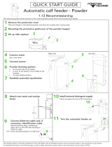
Fig. 1: Safety Equipment
1. Main switch
2. "Warning of hazardous electrical voltage" warning
label
3. Cover of inspection opening with "Warning of injury to
hands" warning label
4. "Warning of hot surfaces" warning label
The red-yellow main switch on the right-hand side of the control cabinet
disconnects the system and any connected units.
Test: With all parts of the system are operational, switch the main switch to
‘Off’
- all of the parts must stop - all the lights must go out.
The screw covers of the inspection openings prevent persons injuring their
hands on the rotating propellers of the stirrers.
Test: Check that the covers of the inspection openings are being used and
are secured with screws
A0428
Fig. 2: Warning labels
I. Warning of injury to hands
II. Warning of hazardous electrical voltage
III. Warning of hot surfaces
Test: Check whether the labels are still affixed and legible.
Safety Equipment
Main switch
Covers of inspection openings
Warning labels
Safety and responsibility
13

2.6 Sound Pressure Level
The sound pressure level is < 70 dB (A) for powdered polymer, according
to EN ISO 11202:1997 (Acoustics - Noise emission from machinery and
equipment)
Safety and responsibility
14

3 Transporting and storing the system
User qualification: trained user, see
Ä Chapter 2.3 ‘Users' qualifications’
on page 11
WARNING!
High system weight
Possible consequence: Death or severe injuries, if the floor
cannot support the system and breaks.
Measure: Ensure that the floor of the installation site can
support the weight of both the empty and full system.
WARNING!
Never stand under suspended loads.
Possible consequence: Fatal or very serious injuries
– It is prohibited to walk under or stand underneath sus‐
pended loads
– When lifting and transporting the Ultromat ensure it
cannot slip or topple
– Use suitable approved lifting tackle. Observe the infor‐
mation given in the lifting equipment data sheets.
– Ultromat
®
systems of type 4000 and 8000 may only be
lifted with a traverse if they are fitted with lifting lugs. The
length of the traverse must be at least 10 - 20 cm longer
than the storage tank
CAUTION!
Possibility of damage to the system during transport
Improper transport can result in system damage.
– Only move the Ultromat
®
system when empty
– The storage tank wall must not be subjected to point
loading
– Avoid heavy vibration and impact loads
– Only move the system with suitable hoisting and lifting
equipment
– When using forklift trucks, use long forks, which extend
across the entire depth of the storage tank
– If a crane is used, attach the slings, even if lifting lugs
are fitted, such that shear forces are avoided
Permissible ambient temperature: -5 °C to +50 °C.
Humidity: None. Rain and condensation not permitted.
Other: No dust, no direct sunlight.
Ambient conditions for storage and trans‐
port
Transporting and storing the system
15

4 Information on the system
The Ultromat
®
manufactured by ProMinent is an automatic polyelectrolyte
preparation system.
It can be used in any application where synthetic polymers are to be auto‐
matically prepared to form polymer solutions e.g. to act as flocculation
aids. As such a dissolving station, the system is suitable for a large
number of process engineering applications, e.g. in the water treatment
sector, in waste water treatment and paper manufacture.
4.1 Design
The system is designed for the fully automatic batching of polymer solu‐
tions.
Almost all commercially available polymers can be used. Under the control
of Ultromat
®
systems, concentrations from 0.05 to 1.0 % can be set. The
viscosity of the polymer solution produced must not however exceed
1500 mPas. Please refer to the polymer suppliers' application data sheets
for information about the viscosity of the different polymer solutions.
Adjust the flow rate of the preparation water to make full use of the prepa‐
ration range. Concentrations of greater than 0.5 % can reduce the
capacity of the preparation performance.
The maturing time available for the production of a polymer solution
depends on the extraction rate and the volumetric capacity of the
Ultromat
®
and is approximately 60 minutes at a maximum extraction rate.
The system capacities extend from max. 400 l usage solution per hour for
the Ultromat
®
400 up to 8,000 l for the Ultromat
®
8000.
4.2 Technical data
Please refer to the dimensions sheet for the precise dimen‐
sions of your Ultromat
®
system
Information on the system
16

Ultromat
®
ULFa
Ultromat
®
ULFa
400 1000 2000 4000 6000 8000
Storage tank volume (l) 400 1000 2000 4000 6000 8000
Extraction rate (l/h) 400 1000 2000 4000 6000 8000
Maturing time (min) 60
Solution concentration
(%)
0.05 - 1.0
Dimensions
LxWxH (mm)
1999x918
x1390
2643x1002
x1740
3292x1186
x1890
3301x1456
x2182
4120x1651
x2182
4605x1910
x2290
Net weight (kg) 190 400 450 600 900 1,200
Total weight (kg) 590 1400 2450 4600 6900 9200
Overflow connection DN 40 DN 50 DN 50 DN 65 DN 65 DN 80
Extraction connection DN 25 DN 25 DN 32 DN 40 DN 40 DN 50
Water supply for redilu‐
tion
1" 1" 1" 1 1/2" 1 1/2" 2"
Liquid concentrate -
pipework
DN 15 DN 15 DN 15 DN 20 DN 20 DN 20
Max. water supply 600 l/h 1,500 l/h 3,000 l/h 6,000 l/h 9000 l/h 12,000 l/h
Electrical rating 1.5 kW 2.6 kW 3.2 kW 5.0 kW 5.0 kW 9.5 kW
External fuse 32 A 32 A 32 A 32 A 32 A 32 A
Degree of protection
control cabinet
IP 55 IP 55 IP 55 IP 55 IP 55 IP 55
Stirrer 1
Performance 0.25 kW 0.55 kW 0.75 kW 1.1 kW 1.1 kW 2.2 kW
Speed (50 Hz) 700 rpm 700 rpm 700 rpm 700 rpm 700 rpm 750 rpm
Degree of protection IP 55 IP 55 IP 55 IP 55 IP 55 IP 55
Stirrer for chambers 2 + 3 (optional)
Performance 0.18 kW 0.55 kW 0.75 kW 1.1 kW 1.1 kW 2.2 kW
Speed (50 Hz) 700 rpm 700 rpm 700 rpm 700 rpm 700 rpm 700 rpm
Degree of protection IP 55 IP 55 IP 55 IP 55 IP 55 IP 55
Powder feeder
Type TGD 11 TGD 11 TGD 18 TGD 55 TGD 55 TGD 110
Maximum capacity 11 kg/h 11 kg/h 18 kg/h 55 kg/h 55 kg/h 110 kg/h
Pressure sensor
Part number 1038273 1038273 1038273 1038273 1038273 1038273
Type dT P30 dT P30 dT P30 dT P30 dT P30 dT P30
Measuring range 0-160 mbar 0-160 mbar 0-160 mbar 0-160 mbar 0-160 mbar 0-160 mbar
Signal 1 - 6 V 1 - 6 V 1 - 6 V 1 - 6 V 1 - 6 V 1 - 6 V
Turbodos
Part number 1025379 1025379 1025379 1025379 1025379 1040023
Pulse/litre 67.5 67.5 67.5 67.5 67.5 26.6
Output PNP PNP PNP PNP PNP PNP
Information on the system
17

Metering pumps of the Ultromat
®
ULFa
Ultromat
®
ULFa
400 1000 2000 4000 6000 8000
Sigma
Type S1CaH 12017 12035 12035 10050 10050 10050
Capacity 17 l/h 35 l/h 35 l/h 50 l/h 50 l/h 50 l/h
Degree of protection IP 65 IP 65 IP 65 IP 65 IP 65 IP 65
Spectra
Type Spectra 12 / 13 F 12 / 33 F 12 / 33 F 12 / 100 F 12 / 100 F 12 / 100 F
Capacity 13 l/h 33 l/h 33 l/h 100 l/h 100 l/h 100 l/h
Degree of protection IP 55 IP 55 IP 55 IP 55 IP 55 IP 55
A0429
Fig. 3: System dimensions
I. Height (H)
II. Width (B)
III. Length (L)
Ambient conditions
Value
Storage and transport temperature - 5 °C ... + 50 °C
Operation temperature + 5 °C ... + 40 °C
Storage and operation air humidity < 92 % relative air humidity (non-condensing)
Powdered polymer air humidity Observe the instructions of the polymer manufacturer. If nec‐
essary use an air dehumidifier
System sound pressure level < 70 dB (A)
Information on the system
18

5 Design and function
5.1 System construction
The system parts for powder storage, powder metering, wetting, dissolving
and maturing of the powder polymers are combined in a compact unit.
An Ultromat
®
is assembled using the identity code from the following func‐
tional units:
n Water fitting (1)
n Concentrate pump (2)
n Stirrers (3)
n Flush fitting (4)
n Powder feeder (5)
n Control cabinet (6)
n Three-chamber storage tank (7)
The flush fittings and water piping are available in either PVC or PP.
A0430
Fig. 4: System construction
The seals are made from EPDM as standard. The stirrer shafts and pro‐
pellers of the stirrers plus the liquid end of the powder feeder are made
from corrosion-resistant stainless steel.
5.2 Description of the Component Assemblies
The units are only available, if they were selected with the
identity code.
Design and function
19

5.2.1 Three-chamber storage tank
A0830
Fig. 5: Extraction openings
1. Ball valve chamber 1
2. Ball valve chamber 2
3. Extraction cock for the matured polymer (chamber 3)
The closed design PP storage tank with stirrer traverses, the brackets for
powder feeder and control cabinet, plug overflow, drainage and extraction
connections is divided into three separate chambers. This ensures suffi‐
cient polymer solution maturing time. The division of the storage tank
largely prevents the mixing of matured and freshly prepared solution and
enables continuous extraction.
All inspection openings of the storage tank are secured with tightly screw‐
able covers.
The liquid level of chamber 3 is continuously measured using a pressure
sensor.
5.2.2 Crane Lifting Lugs
For easier handling of the system, a suitable hoisting device can be
attached to the four lifting lugs.
5.2.3 Water fitting with flush fitting
The water pipework supplies the system with the required preparation
water. The pressure reducer with filter insert ensures that the pressure is
limited and maintained at the correct operating pressure. A solenoid valve
automatically opens and closes the water inlet. The flow meter used, con‐
tinuously reports the current flow rate to the control. During commissioning
the two regulating valves are used to set the water flow rate. The flush fit‐
ting ensures that the polymer powder is intensively wetted with preparation
water. A manual shut-off valve also shuts off the supply of water if mainte‐
nance work is necessary.
There are two versions of flush fitting:
n Y-flush inlet
n Wetting cone
With the wetting cone, the flushing process is more complicated, as
described above:
Design and function
20
Page is loading ...
Page is loading ...
Page is loading ...
Page is loading ...
Page is loading ...
Page is loading ...
Page is loading ...
Page is loading ...
Page is loading ...
Page is loading ...
Page is loading ...
Page is loading ...
Page is loading ...
Page is loading ...
Page is loading ...
Page is loading ...
Page is loading ...
Page is loading ...
Page is loading ...
Page is loading ...
Page is loading ...
Page is loading ...
Page is loading ...
Page is loading ...
Page is loading ...
Page is loading ...
Page is loading ...
Page is loading ...
Page is loading ...
Page is loading ...
Page is loading ...
Page is loading ...
Page is loading ...
Page is loading ...
Page is loading ...
Page is loading ...
Page is loading ...
Page is loading ...
Page is loading ...
Page is loading ...
Page is loading ...
Page is loading ...
Page is loading ...
Page is loading ...
Page is loading ...
Page is loading ...
Page is loading ...
Page is loading ...
Page is loading ...
Page is loading ...
Page is loading ...
Page is loading ...
Page is loading ...
Page is loading ...
Page is loading ...
Page is loading ...
Page is loading ...
Page is loading ...
Page is loading ...
Page is loading ...
Page is loading ...
Page is loading ...
Page is loading ...
Page is loading ...
Page is loading ...
Page is loading ...
Page is loading ...
Page is loading ...
/