Page is loading ...

ProMinent
®
Page 1
Part No. 981638 ProMinent Dosiertechnik GmbH · 69123 Heidelberg · Germany BA VA 008 8/99 GB
Operating Instructions
ProMinent
®
Vario
Metering Pumps
For safe and correct operation of ProMinent
®
Vario metering pumps,
two sets of Operating Instructions are required:
The product-specific Vario Operating Instructions
and ProMinent
®
motor-driven dosing pump. Operating Instructions must be read together!
Please completly read through these operating instructions first! · Do not discard!
The warranty shall be invalidated by damage caused by operating errors!
Stick identification plate here!
DIN EN ISO 9001
70 100 M 502
ProMinent
®
Hotline: 093 824 8589 - Website: www.VinaFluid.com

ProMinent
®
Page 2
Publishing details:
Operating Instructions ProMinent
®
Vario
© ProMinent Dosiertechnik GmbH
ProMinent Dosiertechnik GmbH
Im Schuhmachergewann 5-11
D-69123 Heidelberg
Postfach 101760 · D-69007 Heidelberg
www.prominent.de
Subject to technical modifications
Printed in the F.R. Germany
Publishing details
Hotline: 093 824 8589 - Website: www.VinaFluid.com

ProMinent
®
Page 3
Table of Contents
Page
Product Identification/Identity Code................................................. 4
1 Safety instructions for ProMinent
®
metering pumps .................................................................. 5
1.1 General notes ................................................................. 5
1.2 Notes for installation, commissioning and operation ..... 5
1.3 Notes on servicing and repair......................................... 6
2 Product Description ........................................................... 7
2.1 Marking/Identification of pump type............................... 7
2.2
Construction and functional description of drive unit
8
2.2.1
Diagram showing operation of stroke
..................... 8
2.3 Construction and functional description of
diaphragm delivery unit .................................................. 8
2.3.1 Integrated Overflow Valve with
Bleeder Function .................................................... 9
2.4 The drive motor and the types of control .......................11
2.5 Standards and approvals................................................16
3 Commissioning ....................................................................17
3.1 General notes .................................................................17
3.2 Installing and connecting................................................17
3.3 Commissioning ...............................................................18
3.4 Troubleshooting ..............................................................19
4 Servicing/Maintenance......................................................20
4.1 General servicing notes ..................................................20
4.2 Replacement of wear parts.............................................20
4.3 Spare parts set ............................................................... 21
5 Technical Data .....................................................................22
5.1 Performance data ...........................................................22
5.2 Dimensions sheet ........................................................... 23
5.3 Motor data ...................................................................... 24
6 EC Declaration of Conformity..........................................28
7 Other documents ................................................................29
- Guarantee application for metering pumps...........................29
- Data for dosing pipeline calculations ....................................30
- Installation drawing ............................................................... 31
Hotline: 093 824 8589 - Website: www.VinaFluid.com

ProMinent
®
Page 4
Preis/DM
Product Identification/Identity Code
Product Identification/Identity Code
The device label on the title page is identical to that supplied with the pump in order to facilitate matching the correct operating
instructions manual to the pump.
Please enter the identity code given on the device label into the grey boxes below.
VAMb Vario Diaphragm Metering Pump, Version b
Pump type: (figures 1 + 2 = back pressure [bar], figures 3, 4, 5 = feed rate [l/h])
12017* 12026*
12042* 10025*
09039* 07063*
06047* 05075*
04120* * = for PV, PP, NP and TT versions, max. 10 bar
Liquid end materials:
PVT PVDF, PTFE seal
SST Stainless steel with PTFE seal
PP1, NP1 and TT1 versions are still available (only for use with hydraulic connector: “0”)
Liquid end version:
0 No valve springs -
1 With 2 valve springs, Hastelloy C4, 0.1 bar 22,00
4 With pressure relief valve, Viton seal, no valve spring (PVT version only) 000,00
5 With pressure relief valve, Viton seal and valve spring (PVT version only) 000,00
Hydraulic connectors:
0 Standard connector according to technical data -
1 Union nut and PVC insert -
2 Union nut and PP insert -
3 Union nut and PVDF insert -
4 Union nut and stainless steel insert -
7 Union nut and PVDF hose connector -
8 Union nut and stainless steel hose connector -
Version:
0 With ProMinent label (standard) -
2 Without ProMinent label (standard) 16,00
Electrical power supply:
A 1 ph., 230 V 50/60 Hz Euro plug -
B 1 ph., 230 V 50/60 Hz Swiss plug 11,00
C 1 ph., 230 V 50/60 Hz Austral. plug 16,00
D 1 ph., 115 V 60 Hz USA plug 54,00
S 3 ph., 230/400 V 50/60 Hz (basic type only) 000,00
Control type:
0 Basic type with 1 ph. or 3 ph. motor -
1 Mains switch and fuse + two stage float switch input + 607,00
external contact input + pause function as N/C contact +
dosing monitor input + two colour function display.
2 As 1 but with additional memory function 647,00
3 Mains switch and fuse + two stage float switch input + 729,00
analogue input + pause function as N/C contact +
dosing monitor input + two colour function display.
4 Basic type with Hall sensor
5 Basic type with Namur stroke sensor 000,00
Control variants:
0 For control option 0/5 (basic type) -
control options 1 + 2 only
1 6000 pulse/h -
2 2000 pulse/h -
3 4000 pulse/h -
4 8000 pulse/h -
5 10000 pulse/h -
6 12000 pulse/h -
control type 3 only
A 0...20 mA -
B 4...20 mA -
automatic stroke positioning for control type 0/5 (basic type)
H With stroke positioning motor, 230 V/50/60 Hz 1.170,00
I With stroke positioning motor, 115 V/50/60 Hz 1.170,00
J With stroke control motor, 0...20 mA, 230 V/50/60 Hz 2.370,00
K With stroke control motor, 4...20 mA, 230 V/50/60 Hz 2.370,00
L With stroke control motor, 0...20 mA, 115 V/50/60 Hz 2.370,00
M With stroke control motor, 4...20 mA, 115 V/50/60 Hz 2.370,00
Switch mode relay:
0 No relay (basic type) -
1 With fault indicating relay (N/C) 87,00
2 With pacing relay (N/O) 87,00
3 With fault indicating relay (N/O) 87,00
VAMb _____ ___ ___ ___ ___ ___ ___ ___ ___
Hotline: 093 824 8589 - Website: www.VinaFluid.com

ProMinent
®
Page 5
1 Safety relevant instructions for ProMinent
®
metering
pumps
Safety precautions and important operating instructions are divided into classes and provided
with symbols. Please familiarise yourself with the following designations and symbols.
DANGER:
There is a danger of injury or to life!
WARNING:
There is a danger of injury or the equipment can be seriously damaged!
CAUTION:
The situation demands increased awareness!
NOTE:
Information which is to be noted!
WARNING:
This equipment may only be used for its intended purpose.
1.1 General notes
WARNING:
• Assembly of ProMinent
®
metering pumps with foreign parts which are not tested or
recommended by ProMinent is not permissible and can lead to injury to persons or
damage for which no responsibility is accepted!
• Pumps must be accessible for operating and servicing at all times. Accesses must not
be obstructed or blocked!
• For servicing and repair work where dangerous or unknown dosing media are being
used, first empty and flush out the liquid end! Observe the safety data sheets for the
dosing liquid!
• When metering dangerous or unknown liquids those working on the liquid ends must
wear protective clothing (goggles, gloves)!
1.2 Notes for installation, commissioning and operation
WARNING:
• The metering pump may still contain residual water in the liquid end from testing in the
factory.
• In the case of media which must not come into contact with water, the liquid end must
be cleared of all water before commissioning. To do this rotate the pump 180° and
empty the liquid end and then flush from above through the intake connection using a
suitable medium.
• Do not connect mains voltage to the control cable!
• When operating the metering pump against a closed isolator at the pressure end, the
backpressure can reach several times the maximum permissible backpressure.
This can cause the delivery line to burst!
To avoid this, a pressure relief valve is recommended which limits the backpressure!
CAUTION:
• Design the pressure lines so that pressure peaks on the discharge stroke do not exceed the
maximum permissible pressure (fit a pressure relief valve if necessary)!
• Adjustments to the stroke length should only be carried out with the pump running!
Safety relevant instructions for ProMinent
®
metering pumps
!
!
!
!
!
Hotline: 093 824 8589 - Website: www.VinaFluid.com

ProMinent
®
Page 6
NOTE:
• The pump shall be secured in such a way that no vibration can occur!
The valves of the liquid end must always be vertical to ensure correct operation!
• Intake and delivery pipes must always be arranged such that strain-free connection to the
liquid end is guaranteed!
Pipes shall be secured in such a way that no vibration can occur!
• Use only the locking rings and hose fittings designed for the particular hose diameter and also
use original hoses with the specified hose dimensions and wall thickness, otherwise the
security of the connection is not guaranteed!
Reductions in hose sizes are to be avoided!
The permissible pressure stress of the hoses is to be observed.
• When dosing extremely aggressive or dangerous media an arrangement which relieves back
into the tank is advisable!
Moreover, an shut-off valve should be fitted on the pressure and suction sides!
1.3 Notes on servicing and repair
WARNING:
• Metering pumps and their peripherals may only be serviced by expert and authorised
persons!
• When carrying out servicing or repairs where dangerous or unknown media are used,
always flush the liquid end first!
• When metering dangerous or unknown liquids, those working on the liquid end must
wear protective clothing (goggles, gloves)!
• The pressure in the metering pipe must first be released before working on the pump.
Always empty and flush the liquid end!
Observe the safety data sheets for the metering liquid!
DANGER:
• Isolate the supply cable or withdraw the mains plug before opening the pump.
If the optional relay is fitted, also isolate this!
Check for freedom from voltage!
Always secure the pump against unauthorised restarting during repair work!
• Pumps which are used for dosing radioactive media must not be shipped!
NOTE:
• Pumps must only be returned for repair in a clean condition and with the liquid end flushed
out!
Safety relevant instructions for ProMinent
®
metering pumps
!
!

ProMinent
®
Page 7
Product Description
2 Product Description
CAUTION:
Use in accordance with regulations
The Vario is a diaphragm metering pump for dosing liquid media. Example of use: quantity-
proportional dosing of chlorine bleaching solution to drinking water. Control is achieved by means
of a contact water meter.
Incorrect use
The pump is not designed to dose gaseous media or solids. When dosing chemicals the
resistance of the materials shall be taken into account. Refer to resistance list.
The pump is not suitable for use in explosion-proof areas.
2.1 Marking/Identification of pump type
Each Vario metering pump shall be provided with an identification plate on the side of the foot.
The identity code and serial number shall be given in addition to the normal technical data.
Both these numbers are to be used in all enquiries as they enable the type of metering pump to
be clearly identified.
The meaning of the identity code in the individual pump functions is given in the product
catalogue (refer also to Chapter 5 Technical Data).
Technical modifications reserved.
Identity
code
2687/4.3
!
ProMinent Dosiertechnik TYPE VAMB09039NP11OOA112
Im Schuhmachergewann SER. NO./PN Is / 780873
D-69123 Heidelberg ELECTR. 230 V 50/60 Hz
Tel.: +49 6221/8420 CONNECTION 0.1 kW 0.8 A
Made in Germany DOSING RATE 39.3/47.3 l/h 8.5 bar
ProMinent Heidelberg IP65 - -
Hotline: 093 824 8589 - Website: www.VinaFluid.com

ProMinent
®
Page 8
Product Description
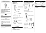
2.2 Construction and functional description of drive unit
The ProMinent
®
Vario is an oscillating displacement metering pump whose stroke length can be
adjusted in steps of 1%. It is driven by a special custom built single phase AC motor or a
standard three phase motor (1). Its drive rotation is reduced by the worm gearing (2) and
transmitted via the eccentric roller (3) to the connecting rod (4) and therefore changed to an
oscillating motion. A powerful return spring (5) holds the connecting rod against the eccentric
roller to provide a return stroke. The length of the stroke is adjusted by using the stroke
adjustment knob (6) and shaft (7) to limit the return stroke. The stroke is transmitted directly to
the piston. In conjunction with the valves, this generates the pressure or vacuum in the liquid end
which is necessary for delivery. The delivery flow is pulsating.
2.3 Construction and functional description of
diaphragm delivery unit
The heart of the delivery unit is the DEVELOPAN
®
metering diaphragm (4). It hermetically seals
the delivery chamber of the liquid end (2) and effects the displacement in the liquid end (2). The
end washer (5) of chemically-resistant plastic separates the drive housing from the delivery part
and protects the drive from corrosion in the event rupture of the diaphragm. The suction valve (1)
and pressure valve (3) which are of identical construction, operate in conjunction with movement
of the diaphragm to provide the delivery operation. The valve balls can be spring-loaded for
metering viscous media.
The connecting dimensions of valves and liquid ends which are the same size but of different
material are the same. The parts can be interchanged as required. An integrated bypass-/bleed
valve may be optionally installed in the PVT version (see page 9).
2095-4.2
1
7
6
3
945
82
2.2.1 Diagram showing operation of stroke
a) Stroke during max. b) with reduced stroke length
number and length of strokes
1 Motor
6 Adjustment of stroke
3 Housing with gearing
8 Discharge unit
9 Protective plug
Pressure
stroke
+
Stroke speed
Angle of rotation eccentric roller
–
Suction
stroke
0 360180
4
6
5
3
8
2
1
2096-4.1
Hotline: 093 824 8589 - Website: www.VinaFluid.com

ProMinent
®
Page 9
CAUTION:
• Knob Item 139 must be turned in clockwise direction as far as it will go „close“.
• The bypass line must always be closed and must be routed back into the supply tank.
Connection via hose connection Item 128.
• Minimal overflow can occur in the bypass line when the valve operates close to the
overpressure function.
The bleeder function is achieved by turning knob Item 139 in counterclockwise direction as far as
it will go „open“: Priming aid for starting up pump against pressure. The force of spring Item 132
relieves ball Item 130 which is controlled by the lower spring force of bleeder spring Item 133.
CAUTION:
• Once the pump has primed, turn knob Item 139 in clockwise direction as far as it will go
„close“! The pump can now be placed into operation.
Technical data
Corresponding to the type of pump, overflow valves are available for pressure stages pnom 3.5/
4.5/5.5/6.5/8.5/10 bar with (1.05...1.4) xpnom opening pressure.
Materials in contact with metered medium
Liquid end: Overflow valve: Seals in overflow Balls: Springs:
valve:
PVDF PVDF Viton O-rings, PTFE Ceramic Hastelloy C4
2.3.1 Integrated Overflow Valve with Bleeder Function
Task
The task of the overflow valve is to protect the motor and gear unit against impermissible
overpressure caused by the metering pump.
This function is produced by a spring-loaded ball.
A pressure relief mechanism for the bleeder function is provided.
Design and Functional Description
Initially, the overflow valve illustrated unter Item 102 operates as a simple directly control safety
valve. As soon as the pressure set with spring Item 132 is exceeded, the effective pressure raises
ball Item 130. The liquid then flows off into the tank via hose connection Item 128.
Product Description
110
3160-4
134
102
133
137
132
138
139
126
125
127
136
128
130
131
142

ProMinent
®
Page 10
!
Use for intended purpose / Use not for intended purpose
Use for intended purpose
To protect the motor and gear unit against impermissible overpressure caused by the metering
pump.
If the pump is the only pressure generator in the system, the overflow valve will also protect the
system automatically.
CAUTION:
• Only for liquids with a viscosity of up to 100 mPa · s
• On pumps with a 1 ph AC motor, the motor is protected by an integrated thermal cutout.
• The ceramic ball and ball seat of the overflow valve are wearing parts. Slight leakage can
occur at the safety valve after a prolonged period of operation. The ball and ball seat should
be replaced if leaks occur.
• The bypass line must always be connected and must be routed back into the supply tank.
• Refer to the installation notes in the operating instructions for „Motor Driven Metering
Pumps“.
Use not for intended purpose
To protect the system from impermissible overpressure which has other causes than the
pressure generated by the metering pump.
The pump must not be operated without the bypass line connected.
Connection of the bypass line in the intake line is not permitted as this would impair the
effectiveness of the bleeder function.
DANGER:
When carrying out maintenance work on the overcurrent valve, pay attention to the
tensioning state of the pressure spring Item 132! Wear safety goggles!
Product Description

ProMinent
®
Page 11
- Mains cable (1)
- On/Off switch (2)
- Safety switch (3)
2132-4.2
3
12
PG11
Switch
Product Description
2.4 The drive motor and the types of control
1-phasen motor
The single phase drive motor has integrated thermal overload protection. This activates to switch
off the motor if the maximum permitted temperature is reached during operation.
NOTE:
• After the stationary motor has cooled down, the thermal overload automatically resets.
CAUTION:
• After the motor has been shutdown by the thermal overload, check that the pump is not being
permanently overloaded. Constant switching on and off of the motor by the terminal overload
is to be avoided (refer also to Chapter 5.3 Technical Data).
Standard 3-phase motor
The Vario basic type (controller type 0) is optionally available with a 3-phase dual wound motor,
3-pH. 230/400 V, 50/60 Hz. It can be connected directly to the terminal box on site (see also
section 5.3, Technical Data).
Controller type 0: (basic type with 1-pH. motor)
This controller type is fitted with a mains connector (1), an externally accessible fine-wire fuse (3)
and an illuminated mains switch (2). Dosing is continuous.
Miniature fuse
The miniature fuse is triggered by electrical defects in the control system of the motor or by
overload.
Fuse data: (refer to spare parts list)
The fuse can be changed without opening the pump control unit. All that is required is to open
the screwed cap on fuse holder (3) and replace the defective fuse by a new one of the same type.
DANGER:
• Before changing a fuse, switch off the pump and disconnect from the mains.
Controller type 4 (basic type with stroke sensor)
This type of control unit has a mains connection (1), a miniature fuse accessible from the outside
(3) and an illuminated 2-pole mains switch (2). Metering is continuous. Furthermore, the stroke
sensor is fitted in the pump so that it is possible to change the control unit for a different type.
!

ProMinent
®
Page 12
Controller type 5 (basic type with Namur-type stroke sensor)
Product Description
Switch aperture s
n
inset 1.5 mm flush
See figure above
Electrical cabling: DC, two wire, as DIN 19 234 (NAMUR)
Fixtures:
as DIN 19 234 (NAMUR) NJ 1.5-8GM-N
Features:
Operating switch apertures s
a
0 - s
a
- 0.81 s
n
Reduction factor at V2A 0.85; Al 0.4; Cu 0.3
Reproducibility R - 0.01 mm
Switch hysteresis H approx. 10 %
Standard measurement plate
1 mm Fe 8 mm x 8 mm
Operating voltage U
B
5 bis 25 V DC
Residual ripple - 5 %
Switch frequency f 5 kHz
Electrical Data:
Standard voltage 8 V DC (Ri approx. 1 k/ohm)
Individual inductivity 20 µH
Individual capacity 16 nF
Output/power uptake
active surface free - 3 mA
active surface covered - 1 mA
Mechanical Data:
Ambient temperature 248 - 373 Kelvin
(-25 °C bis +100 °C)
Enclosure rating as DIN 40 050 IP 67
Permissible impact and b - 30g, T - 11 ms
Oscillation stress f - 55 Hz, a - 1 mm
Connector 2 m, PVC lead, 0.14 mm
2
Standard symbol/connection:
Material stainless steel
key width 13, thickness 4
M8x1
22
(60)
x
BM
BU
N
+
DC
-

ProMinent
®
Page 13
Product Description
Control unit Type 1: (contact type)
This type of control unit has a mains connection, an illuminated 2-pole mains switch, a multi-
coloured operating/fault indicator, a 2-stage level input, a metering monitoring input, an external
contact input and a mode changeover switch. The operation of the motor is additionally
monitored by means of an electronic safety device.
The contact type of control unit can also be supplied with a fault relay with a normally-closed or
normally-open contact or a timer relay as an option. Where the fault relay or timer relay is used
with a normally-open contact, the relay closes for approximately 4 seconds when the power is
switched on, before it changes to its selected operating state.
Controls: - Mains cable (1)
- On/Off switch (2)
- Socket for level switch (4)
- LED indicator (5)
- PG 9 blanking plug or, where there is fault/
timer relay ident code choice, a 3-core cable –
with a PG 9 union (6)
- Socket for monitoring dosing (7)
- Internal/external changeover switch (8)
- Socket for external control/interval function (9)
NOTE:
• The connecting sockets (4 and 9) must always be occupied, either by functional plugs or level
switches or contact/control cables! Always keep removed functional plugs for re-use!
Level input
The level input (4) is arranged as a normally-closed switch as standard and has both functions,
early warning and shutdown. In the event of level early warning the function indicator changes
from dark to red or from green to orange. If a fault relay is fitted its state changes. In the event of
a level shutdown the function indicator changes to red and the motor is stopped in the O-stroke
position, and if a fault relay is fitted the switching state changes.
Metering monitoring input
The metering monitoring input (7) is used to monitor the metering process. ProMinent metering
monitoring sensors can be connected to the input. If the feedback from a connected metering
monitoring sensor is absent for at least eight metering strokes, the pump goes to a fault
condition. The function indicator changes to red, the motor is stopped in the O-stroke position,
and if a fault relay is fitted it changes the switching state. The fault can only be reset by switching
the mains power (on/off switching) or by a brief level change at the input pin of the contact input.
2624-4
switch
PG11
PG9
162
4597 8
int.
ext.

ProMinent
®
Page 14
Product Description
External input
The external input (9) is used for external contact control of the pump or for a floating on/off
switching (interval function) of the pump. The interval input operates as a normally-closed
contact, i.e. when the input is open the pump is shutdown and when it is closed it is ready for
operation. In the contact mode the number of motor switch-ons is limited to approximately 2000
switch-ons per hour. If the number of strokes to be carried out exceeds 2000, then multiple
strokes are performed. The factor (can be set inside the pump) is selected such that the motor is
operated continuously where there is the maximum number of input pulses (exception 60 Hz
operation). Matching to the maximum incoming, external pulses is possible in principle, except
for the possibilities (6000; 2000; etc) indicated in the ident code.
The control algorithm which takes place in the microprocessor guarantees that the incoming
external signal is converted to the corresponding number of stroke within the control period of
one minute.
Electronic safety device
The electronic safety device (rotation monitoring) is fitted as standard to control unit types 1, 2
and 3. The control unit registers each discharge stroke by means of a sensor. If longer than the
previous control time of approximately 1 s is required for a discharge stroke, this stroke is
regarded as not performed and the control unit indicates a fault (red LED).
The electronic safety device serves mainly to protect against overload during startup of the drive
(e.g. on commissioning) or to provide a rapid shutdown of the pump if the gears or any parts of
the motor are jammed.
WARNING:
• The pressure conditions in the metering system are to be checked and corrected as
necessary before initial commissioning.
A functional check of the metering pump is also to be carried out. The fault can only be
reset if the mains is switched (off/on switching of the mains switch) or if there is a brief
level change at the switching pin of the external input.
Miniature fuse
The miniature fuse is triggered by electrical defects in the control system or motor. Because in
the case of most defects (e.g. motor overload) the electronic safety device (rotation monitoring)
respond first, the miniature fuse reacts only in exceptional cases. The miniature fuse is located on
the board inside the pump control unit.
Fuse data: (refer to spare parts list).
WARNING:
• The fuse may only be changed by an authorised Customer Service
Control unit Type 2: (contact memory control unit)
The type 2 control unit is the same as the type 1 control unit except for the contact mode. In the
contact mode incoming impulses which arrive faster than the pump can perform discharge
strokes can be buffer stored in an internal memory with a maximum memory capacity of 655355
discharge strokes, and then performed.
!
!

ProMinent
®
Page 15
Product Description
Control unit Type 3: (analogue type of control unit)
This type of control unit has a mains connection, an illuminated 2-pole mains switch, multi-
coloured operating/fault indicator, a 2-stage level input, a metering monitoring input,
an external analogue input and a mode changeover switch. The operation of the motor is
additionally monitored by means of an electronic safety device.
The analog type of control unit can be supplied with a fault relay or timer relay as an option.
Controls: - Mains cable (1)
- On/Off switch (2)
- Socket for level switch (4)
- LED indicator (5)
- PG 9 blanking plug or, where there is fault/
timer relay ident code choice,
a 3-core cable with a PG 9 union (6)
- Socket for monitoring dosing (7)
- Internal/external changeover switch (8)
- Socket for external control/interval function (9)
NOTE:
• The connecting sockets (4 and 9) must always be occupied, either by functional plug or level
switches or contact/control cables. Always keep removed functional plugs for re-use.
Level input
The level input (4) is arranged as a normally-closed switch as standard and has both functions,
early warning and shutdown. In the event of level early warning the function indicator changes
from dark to red or from green to orange. If a fault relay is fitted its state changes. In the event of
a level shutdown the function indicator changes to red and the motor is stopped in the O-stroke
position, and if a fault relay is fitted the switching state changes.
Metering monitoring input
The metering monitoring input (7) is used to monitor the metering process. ProMinent metering
monitoring sensors can be connected to the input. If the feedback from a connected metering
monitoring sensor is absent for at least eight metering strokes, the pump goes to a fault
condition. The function indicator changes to red, the motor is stopped in the O-stroke position,
and if a fault relay is fitted it changes the switching state. The fault can only be reset by switching
the mains power (on/off switching) or by a brief level change at the input pin of the contact input.
External input
The external input (9) is used for external analog control of the pump or for floating switch-on and
switch-off (interval function) of the pump. The interval input operates as a normally-closed
switch, i.e. when the input is open the pump is stationary and when the input is closed it is ready
for operation.
Switch
PG11
PG9
162
4597 8
int.
ext.
2624-4

ProMinent
®
Page 16
Product Description
The control algorithm ensures that within the control period of one minute the incoming external
signal is correctly converted to the corresponding number of strokes.
Electronic safety device
The electronic safety device (rotation monitoring) is fitted as standard to control unit types 1, 2
and 3. The control unit registers each discharge stroke by means of a sensor. If longer than the
previous control time of approximately 1 s is required for a discharge stroke, this stroke is
regarded as not performed and the control unit indicates a fault (red LED).
The electronic safety device serves mainly to protect against overload during startup of the drive
(e.g. on commissioning) or to provide a rapid shutdown of the pump if the gears or any parts of
the motor are jammed.
WARNING:
• The pressure conditions in the metering system are to be checked and corrected as
necessary before initial commissioning.
A functional check of the metering pump is also to be carried out.
The fault can only be reset if the mains is switched (off/on switching of the mains switch)
or if there is a brief level change at the switching pin of the external input.
Miniature fuse
The miniature fuse is triggered by electrical defects in the control system or motor. Because in
the case of most defects (e.g. motor overload) the electronic safety device (rotation monitoring)
respond first, the miniature fuse reacts only in exceptional cases. The miniature fuse is located on
the board inside the pump control unit.
Fuse data: (refer to spare parts list).
WARNING:
• The fuse may only be changed by an authorised Customer Service.
2.5 Standards and approvals
EC guidelines
EC Pump Guideline (89/392/EEC) as amended by 93/44/EEC
EC Low Voltage Guideline (73/23/EEC)
EC EMC Guideline (89/336/EEC) as amended by 92/31/EEC, in course of preparation
International standards
EN 292-1 Safety of pumps
EN 292-2 Safety of pumps
EN 60335-1 A6 Safety of electrical equipment for household use
EN 60335-2-41 Safety of electrical equipment, special pumps
The 100 V and 115 V version corresponds to the following:
CSA Standard C22.2No. O-M91 General requirements
CSA Standard C22.2No. 108-M89 Liquid pumps
National standards
Safety of electrical DIN VDE 0700, Part 1 Corresponding to EN 60335.1 and IEC335.1
equipment in DIN VDE 0700, Part 41 Corresponding to EN 60335-2-41 and
accordance with the IEC 335-2-41
following: DIN VDE 0700, Part 500 Routine testing of equipment
DIN VDE 0530, Part 5 Rotating electrical pumps
DIN VDE 0110 b Clearances and creepage distances
Radio suppression DIN VDE 0871 B Radio suppression of high frequency equipment
Tests and approvals of components used
a) Pumps VDE 0551 Mains transformer
VDE 0565, Part 1 Interference suppression capacitors
VDE 0611, Part 1 Series terminals for mains power connection
VDE 0820, Part 1 Equipment protective devices
VDE 0560-8 Motor capacitor
VDE 0435 Electrical relays (optional)
VDE 0530 Motor
!
!

ProMinent
®
Page 17
3 Commissioning
3.1 General notes
The pulsating operation of the ProMinent
®
Vario as an oscillating displacement metering pump
causes high pressure differences in the pipes on each discharge stroke. If these pressure
differences are too great because of unsatisfactory lines, it can lead to high metering errors or to
failure of the metering pump. When dosing very viscous media or where the metering lines are
very long, a larger internal diameter for the pipe should be chosen if necessary and/or a
compressed air chamber or diaphragm pulsation damper should be fitted.
WARNING:
• Check that the materials used can withstand the chemicals which are being metered
(refer to ProMinent
®
Resistance List in the Product Catalogue).
WARNING:
• The safety notes in Chapter 1 must be observed.
3.2 Installing and connecting
- The metering pump must not be restrained by the cover (recognisable by the ventilation slots)
for transport or packing. Danger of damage.
- The metering pump must be installed vertically with its base on a horizontal support.
- The intake and delivery lines shall be laid in such a way that the coupling to the liquid end is
free of mechanical strain.
- The pumps and pipes shall be secured so that no vibration can occur.
- The pipes shall be attached in such a way that the pump and liquid end can be moved
sideways if necessary.
- When metering extremely aggressive or dangerous media it is advisable to have a relief back
to the tank and to have an isolating valve on both the delivery and intake side.
- If the installation instructions are complied with and the stroke length is greater than 30%, a
reproducible metering accuracy of more than ± 2% is obtained.
Delivery line
- The delivery line shall be designed in such a manner that pressure peaks on the discharge
stroke do not exceed the maximum permissible operating pressure.
- To protect against overload, a pressure relief valve with a return to the feed tank is to be
provided on the pressure side.
- A pressure relief valve shall always be fitted in conjunction with a compressed air chamber or
pulsation damper.
WARNING:
• Motorised metering pumps may under certain circumstances work against a substantially
increased operating pressure for short periods without the electrical safety devices
responding.
For this reason the maximum permissible operating pressure must be complied with to
protect against accidents and premature wear.
Intake line
- The intake line must always be laid vertically.
- It should be as short as possible.
- It shall be dimensioned with regard to cross-section and length such that vacuum which
occurs on suction does not reach the vapour pressure of the medium to be metered.
- Curves should be used where possible instead of angles for bends.
- Excessive vacuum on the intake side leads in extreme cases to a break in the column of liquid
or to an incomplete return stroke (the return stroke can no longer be detected at the stroke
adjusting knob).
- The product h · rho shall not exceed the specified maximum suction head.
h = geodetic height
rho = density
e.g.: h = 2 m rho = 1.48 2 · 1.48 = 2.96 mWS (mWG)
For details of the suction head refer to Chapter 5.1, page 22 „Performance data“.
- It must also be guaranteed that no overload of the drive unit occurs on the suction side.
Where there is a positive suction head the above limits shall be observed.
- The suction line shall be dimensioned such that no overload occurs at the end of the suction
stroke due to mass lag.
!
!
!
Commissioning

ProMinent
®
Page 18
Meter rate relative to stroke length
(Vario with FM 042)
Hublänge in (%)
Meter rate relative to stroke length Meter rate relative to stroke length
(Vario with FM 063) (Vario with FM 120)
Stroke length in (%) Stroke length in (%) 2070-4
Q (l/h)
Q (l/h)
Q (l/h)
2100-4
0 20 40 60 80 100 0 20 40 60 80 100
VAMb
06047
VAMb
05075
VAMb
04120
120
80
40
VAMb
10025
VAMb
09039
VAMb
07063
60
50
40
10
20
30
VAMb
12017
VAMb
12026
VAMb
12042
40
30
20
10
Stroke length in (%)
1 rotation (360 º) 50 % stroke length 2625-4.1
Pipe calculations
The necessary lines can be calculated in accordance with the „Calculations of metering lines“
instructions.
If all the necessary data in accordance with the Data Sheet (refer to annex) is submitted, the
metering lines can be quickly checked in the works free of charge.
3.3 Commissioning
- Check correct installation in accordance with the aforementioned points and installation notes.
- Bleed the pressure side. Switch on the pump and allow to operate at maximum stroke length
until the liquid end is charged. Switch off the pump.
- Close the bleed on the pressure side, if necessary open the shut off valve in the discharge line
and allow the pump to operate.
- Check the response pressure of the pressure relief valve.
-
Set the required meter rate in accordance with the „Meter rate relative to stroke length“ diagram.
- Check the meter rate and correct if necessary.
Diagram for setting the meter rate
Setting the stroke length
30 % 75 % 100 %
Commissioning
120
80
40
VAMb
12042
VAMb
07063
VAMb
04120
p [bar]
0
^
=

ProMinent
®
Page 19
3.4 Troubleshooting
Symptom Possible cause Remedy
- Suction head too high
- Back pressure in the injection line
(pressure side)
- Install pump closing to feed tank
- Remove backpressure,
(e.g. via bypass line)
- No metering even though the drive is
running (after long operation)
- Stroke setting 0%
- Feed tank empty
- Gas bubble in intake line and liquid
end
- Leakage of metering liquid at the leak
outlet of the liquid end
- Defective diaphragm
- Loss of metering performance
(after long operation)
- Defective wear parts in the valves
- Deposits in the valves
- Replace (refer to Chapter 4.2)
- Clean or replace valve parts
(refer to Chapter 4.2)
- Dosing pump stops (1 ph. motor)
(controller types 0, 4 and 5)
- Check pressure in metering line and
correct as necessary.
Check ambient temperature and reduce as
necessary.
Motor switches off automatically in
operation after cooling.
- Check pressure in the metering line and
correct as necessary. Replace fuse
(refer to Chapter 2.4 Type 0 control unit).
- Dosing pump stops (1 ph. motor)
Red LED is lit
(controller types 1, 2 and 3)
- Temperature monitor on motor has
switched off because ambient
temperature is too high
- The rotation monitoring of the drive
has switched off due to overload
- Check ambient temperature and reduce as
necessary. After cooling down, clear the
fault by switching the mains switch off and
on
- Check pressure conditions in the metering
pipeline and correct as necessary. Clear
the fault by switching the mains switch off
and on.
- Replace diaphragm (refer to Chapter 4.2)
- Temperature monitor on motor has
switched off due to ambient
temperature being too high or due
to overload
- Miniature fuse defective due to
overload or electrical defect
- Metering pumps does not suck
(on commissioning)
- Increase stroke length (➍100 %)
- Replenish metering medium and restart
system
- Bleed intake line, check for leaks and
restart system
Commissioning

ProMinent
®
Page 20
4. Servicing/Maintenance
4.1 General servicing notes
- The servicing of Vario metering pumps is limited to checking the metering line and checking
for leaks.
- The gearing is lubricated for life by packing with grease.
(Type 1: Klüber ISOFLEX Topas NB 5051), capacity 24 ml).
- Spare parts are given in the accompanying spare parts list.
- The individual parts given in the spare parts list are regarded as wear parts.
WARNING:
• The safety precautions given in Chapter 1 must be complied with.
4.2 Replacement of wear parts
Replacement of diaphragm
Flush the line (in the case dangerous media wear protective gloves and goggles). Switch off
the pump and disconnect from the mains. Undo the unions on the valve and slacken the head
bolts until free but do not remove. Hold the connecting rod against rotation by using an open-
ended spanner through the opening in the head washer (5). Detach the diaphragm (4) from the
head/diaphragm/head washer (8/2/4/5) assembly by turning sharply counter-clockwise.
CAUTION:
• Valves must be free of connecting pipes.
Remove the diaphragm. Clean the sealing surfaces. Hold the head washer in front of
connecting rod (6) (drain hole downwards) and screw a new diaphragm onto the connecting
rod. After the diaphragm has reached its stop, continue turning until the hole pattern aligns
with the threaded holes. Place the liquid end in position and tighten (ensure correct direction
of flow). Connect the valves. Switch on the pump and check the liquid end for leaks.
Replacement of valve parts
Flush the line (in the case of dangerous media wear protective gloves and goggles). Switch off
the pump and disconnect from the mains. Slacken the connecting unions. Unscrew valve (1)
and remove. Where the „valve assembly“ is being changed clean the sealing surfaces and fit
the new valve and seal in place and tighten. Connect up. Switch on the pump and check the
connections for leaks.
If the internal parts of the valves are being exchanged, unscrew and remove the valve and
slacken the valve seat bush using a special tool and unscrew. Replace the parts as necessary
and reassemble in reverse order. Clean the sealing faces. Continue as before.
WARNING:
• Repairs to electrical equipment may only be carried by qualified electricians. Serious
danger can arise to the user due to incorrect repairs. Repaired electrical equipment
must be subjected to a function and safety inspection in accordance with the valid
regulations of the consumer country.
DISPOSAL OF OLD PARTS
- Old parts are waste „which the user wishes to get rid of“.
- Waste is to be disposed of through an „ordered disposal to preserve the good of the
general public, and particularly for the protection of the environment“. For this reason old
parts must be disposed of in accordance with the Law on the Avoidance and Disposal of
Waste (Waste Law AbfG), or sent for recycling.
- The municipal and community collecting point for special waste or an old parts disposal
organisation contracted by the municipality and community takes the old parts.
3
8
2
4
6
5
1
2096-4.1
!
!
Servicing/Maintenance
/