Page 1 of 8
Installation and Operation Instructions
MATRIX
®
Compatible OBDII Interface
Dodge 2016+ Charger/Durango
IMPORTANT! Read all instructions before installing and using. Installer: This manual must be delivered to the end user.
WARNING!
Failure to install or use this product according to manufacturer’s recommendations may result in property damage, serious injury, and/
or death to those you are seeking to protect!
Do not install and/or operate this safety product unless you have read and understood the safety information
contained in this manual.
1. Proper installation combined with operator training in the use, care, and maintenance of emergency warning devices are essential to
ensure the safety of emergency personnel and the public.
2. Emergency warning devices often require high electrical voltages and/or currents. Exercise caution when working with live electrical
connections.
3. This product must be properly grounded. Inadequate grounding and/or shorting of electrical connections can cause high current arcing,
which can cause personal injury and/or severe vehicle damage, including re.
4. Proper placement and installation is vital to the performance of this warning device. Install this product so that output performance of
the system is maximized and the controls are placed within convenient reach of the operator so that they can operate the system without
losing eye contact with the roadway.
5. It is the responsibility of the vehicle operator to ensure daily that all features of this product work correctly. In use, the vehicle operator
should ensure the projection of the warning signal is not blocked by vehicle components (i.e., open trunks or compartment doors),
people, vehicles or other obstructions.
6. The use of this or any other warning device does not ensure all drivers can or will observe or react to an emergency warning signal.
Never take the right-of-way for granted. It is the vehicle operator’s responsibility to be sure they can proceed safely before entering an
intersection, drive against trac, respond at a high rate of speed, or walk on or around trac lanes.
7. This equipment is intended for use by authorized personnel only. The user is responsible for understanding and obeying all laws
regarding emergency warning devices. Therefore, the user should check all applicable city, state, and federal laws and regulations. The
manufacturer assumes no liability for any loss resulting from the use of this warning device.

Page 2 of 8
Unpacking and Pre-Installation:
Carefully remove the product from its packaging. Examine the unit for transit damage and locate all parts as detailed in the Kit Contents table
below. If damage is found or parts are missing, contact the transit company or Code 3 customer support. Do not use damaged or broken
parts.
This device is a Matrix® compatible interface between the OEM CAN network and the Code 3 Matrix® system. It allows the user to congure
system operations that respond to OEM data.
Kit Contents Table
OBDII Device – Matrix
®
Compatible
OBDII Harness
Installation and Mounting - Durango:
Before proceeding with installation, plan all wiring and cable routing.
Step 1. Gently pry the forward end of the driver’s door sill step plate up disengaging the forward most latch.
Step 2. Pull up the door weather strip starting from the front of the door sill step plate and ending just above the top of the dash.
Step 3. Ensure that the parking brake is disengaged, next gently pry the drivers side kick panel up from the bottom edge rolling it out from
beneath the parking brake pedal.
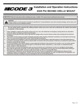
Step 4. Remove the driver’s side dash end-cap, locate the green CAN BUS terminal block as shown in FIGURES 1 & 2.
Figure 1
CAN Connection point
located behind dash
Figure 2
CAN
Connection

Page 3 of 8
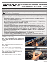
Connector
Figure 3
Figure 4
OBDII Device
To OEM CAN-C Port
To Matrix Compatible Device
Step 5. Route the CAN BUS connection wire up and through the dash to the green terminal block located in FIGURE 3.
Step 6. Connect the cable to any available open port on the CAN BUS terminal.
Step 7. Tuck and secure any excess cabling under the dash, up and away from vehicle controls (e.g. pedals). Ensure that the cabling does
not interfere with proper operation of the vehicle. The remaining unused OBDII Harness connectors will be routed back to the OBDII Device
and another Matrix
®
compatible device.
Installation and Mounting - Durango (continued):

Page 4 of 8
Installation and Mounting - Charger:
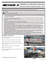
Connector
Figure 6
Step 1. Located below the glove box, remove push in rivets to remove panel shown in FIGURE 5.
Step 2. Locate the OEM CAN-C port shown in FIGURE 6. This will be located behind the dash, below the glove box, facing the oorboard,
on the passenger side.
Step 3. Connect the 2-pin connector from the OBDII Harness to the CAN-C port, as seen in FIGURE 6.
Note: Any open location on the CAN-C port is applicable.
Step 4. Tuck and secure any excess cabling under the dash, up and away from vehicle controls (e.g. pedals). Ensure that the cabling does
not interfere with proper operation of the vehicle. The remaining unused OBDII Harness connectors will be routed back to the OBDII Device
and another Matrix
®
compatible device.
Figure 5
Push-in Rivets

Page 5 of 8
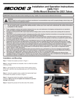
Figure 7
OBDII Device
To OEM CAN-C Port
To Matrix Compatible Device
Installation and Mounting - Charger (continued):

Page 6 of 8
Notes:
1. Larger wires and tight connections will provide longer service life for components. For high current wires it is highly recommended
that terminal blocks or soldered connections be used with shrink tubing to protect the connections. Do not use insulation displacement
connectors (e.g., 3M Scotchlock type connectors).
2. Route wiring using grommets and sealant when passing through compartment walls. Minimize the number of splices to reduce voltage
drop. All wiring should conform to the minimum wire size and other recommendations of the manufacturer and be protected from moving
parts and hot surfaces. Looms, grommets, cable ties, and similar installation hardware should be used to anchor and protect all wiring.
3. Fuses or circuit breakers should be located as close to the power takeo points as possible and properly sized to protect the wiring and
devices.
4. Particular attention should be paid to the location and method of making electrical connections and splices to protect these points from
corrosion and loss of conductivity.
5. Ground termination should only be made to substantial chassis components, preferably directly to the vehicle battery.
6. Circuit breakers are very sensitive to high temperatures and will “false trip” when mounted in hot environments or operated close to their
capacity.
Wiring Instructions:
Caution: Disconnect the battery before wiring up the product to prevent accidental shorting, arcing, and/or electrical shock.
Step 5. Route the remaining, unused OBDII Harness connectors to the
location where the OBDII Device will be mounted. The OBDII Device
must be mounted near another Matrix
®
compatible device with a 4 Pin
AUX connector. Conrm that the cable length is sucient to reach both
required locations. See FIGURE 7 for further details.
Step 6. Connect the OBDII Device to the 14 Pin connector on the
OBDII Harness. Secure the device away from moving parts. See
FIGURE 8.
Step 7. Connect the 4 Pin connector of the OBDII Harness to a Matrix
®
compatible device, which may be the central node of the system (e.g.
Serial Interface Box or Z3 Serial Siren).
The OBDII interface is designed to interact with other Matrix
®
compatible products out of the box using default settings. However, device
operation can be further congured using the Matrix
®
Congurator.
Figure 8
OBD Signal - Default Functions
Input Function
Driver Side Door Open Driver Side Cut (Lightbar)
Passenger Side Door Open Passenger Side Cut (Lightbar)
Rear Hatch Door Open Rear Cut (Lightbar)
High Beams = ON Takedown (Lightbar)
Left Turn Signal = ON N/A
Right Turn Signal = ON N/A
Brake Pedal Engaged Rear Steady Read (Lightbar)
Key Position = ON N/A
Transmission Position = PARK Park Kill
Transmission Position = REVERSE B6 Output Activated (Siren)

Page 7 of 8
All products are thoroughly tested prior to shipment. However, should you encounter a problem during installation or during the life of the
product, follow the guide below for troubleshooting and repair information. If the problem cannot be rectied using the solutions given below,
additional information may be obtained from the manufacturer - contact details are at the end of this document.
Troubleshooting:
Problem Possible Cause(s) Comments / Response
OBDII Device
not functional
Improper connection between the OBDII
Device and the Matrix
®
network
Verify that all harness connections to and from the OBDII Device
are properly seated and secure
Matrix
®
network is inactive (sleep mode)
An ignition input is required to bring the Matrix network out of a
sleep state, if the timeout period has already expired. Refer to
the user manual for your particular Matrix central node (e.g. SIB
or Z3X Siren, etc) for more information on how to wakeup the
network with an ignition input

Page 8 of 8
10986 North Warson Road
St. Louis, MO 63114
Technical Service
(314) 996-2800
www.code3esg.com
An ECCO SAFETY GROUP™ Brand
www.eccosafetygroup.com
Product Returns:
If a product must be returned for repair or replacement*, please contact our factory to obtain a Return Goods Authorization Number (RGA
number) before you ship the product to Code 3®, Inc. Write the RGA number clearly on the package near the mailing label. Be sure you use
sucient packing materials to avoid damage to the product being returned while in transit.
*Code 3®, Inc. reserves the right to repair or replace at its discretion. Code 3®, Inc. assumes no responsibility or liability for expenses incurred for the removal and /or reinstallation of products requiring
service and/or repair.; nor for the packaging, handling, and shipping: nor for the handling of products returned to sender after the service has been rendered.
Manufacturer Limited Warranty Policy:
Manufacturer warrants that on the date of purchase this product will conform to Manufacturer’s specications for this product (which are avail-
able from the Manufacturer upon request). This Limited Warranty extends for Sixty (60) months from the date of purchase.
DAMAGE TO PARTS OR PRODUCTS RESULTING FROM TAMPERING, ACCIDENT, ABUSE, MISUSE, NEGLIGENCE, UNAPPROVED MODIFICA-
TIONS, FIRE OR OTHER HAZARD; IMPROPER INSTALLATION OR OPERATION; OR NOT BEING MAINTAINED IN ACCORDANCE WITH THE
MAINTENANCE PROCEDURES SET FORTH IN MANUFACTURER’S INSTALLATION AND OPERATING INSTRUCTIONS VOIDS THIS LIMITED WAR-
RANTY.
Exclusion of Other Warranties:
MANUFACTURER MAKES NO OTHER WARRANTIES, EXPRESS OR IMPLIED. THE IMPLIED WARRANTIES FOR MERCHANTABILITY, QUALITY
OR FITNESS FOR A PARTICULAR PURPOSE, OR ARISING FROM A COURSE OF DEALING, USAGE OR TRADE PRACTICE ARE HEREBY EX-
CLUDED AND SHALL NOT APPLY TO THE PRODUCT AND ARE HEREBY DISCLAIMED, EXCEPT TO THE EXTENT PROHIBITED BY APPLICABLE
LAW. ORAL STATEMENTS OR REPRESENTATIONS ABOUT THE PRODUCT DO NOT CONSTITUTE WARRANTIES.
Remedies and Limitation of Liability:
MANUFACTURER’S SOLE LIABILITY AND BUYER’S EXCLUSIVE REMEDY IN CONTRACT, TORT (INCLUDING NEGLIGENCE), OR UNDER ANY
OTHER THEORY AGAINST MANUFACTURER REGARDING THE PRODUCT AND ITS USE SHALL BE, AT MANUFACTURER’S DISCRETION, THE
REPLACEMENT OR REPAIR OF THE PRODUCT, OR THE REFUND OF THE PURCHASE PRICE PAID BY BUYER FOR NON-CONFORMING PROD-
UCT. IN NO EVENT SHALL MANUFACTURER’S LIABILITY ARISING OUT OF THIS LIMITED WARRANTY OR ANY OTHER CLAIM RELATED TO
THE MANUFACTURER’S PRODUCTS EXCEED THE AMOUNT PAID FOR THE PRODUCT BY BUYER AT THE TIME OF THE ORIGINAL PURCHASE.
IN NO EVENT SHALL MANUFACTURER BE LIABLE FOR LOST PROFITS, THE COST OF SUBSTITUTE EQUIPMENT OR LABOR, PROPERTY
DAMAGE, OR OTHER SPECIAL, CONSEQUENTIAL, OR INCIDENTAL DAMAGES BASED UPON ANY CLAIM FOR BREACH OF CONTRACT, IM-
PROPER INSTALLATION, NEGLIGENCE, OR OTHER CLAIM, EVEN IF MANUFACTURER OR A MANUFACTURER’S REPRESENTATIVE HAS BEEN
ADVISED OF THE POSSIBILITY OF SUCH DAMAGES. MANUFACTURER SHALL HAVE NO FURTHER OBLIGATION OR LIABILITY WITH RESPECT
TO THE PRODUCT OR ITS SALE, OPERATION AND USE, AND MANUFACTURER NEITHER ASSUMES NOR AUTHORIZES THE ASSUMPTION OF
ANY OTHER OBLIGATION OR LIABILITY IN CONNECTION WITH SUCH PRODUCT.
This Limited Warranty denes specic legal rights. You may have other legal rights which vary from jurisdiction to jurisdiction. Some jurisdic-
tions do not allow the exclusion or limitation of incidental or consequential damages.
© 2019 Code 3, Inc. all rights reserved.
920-0758-00 Rev. B
Warranty:
/