GE HTDX100GM1WW Installation guide
- Category
- Sanitary ware
- Type
- Installation guide

Installation
Instructions l'°so r'er1@
Questions on Installation? Call: 800.GE.CARES (US)
or visit our web site at: www.GEAppliances.com (US)
BEFOREYOU BEGIN
Read these instructions completely and
carefully.
•IN PORTANT-Save these instructions for
local inspector's use.
•IMPORTANT- Observe all governing codes
and ordinances.
• Note to Installer - Besureto leavethese
instructionswith thecustomer.
• Note to Customer - Keep these instructions
with your Owner's Hanual for future reference.
• Before the old dryer is removed from service or
discarded, remove the dryer door.
• inspect the dryer exhaust outlet and straighten
the outlet walls if they are bent.
• Service information and the wiring diagram
are locatedin thecontrolconsole.
• Donotallowchildrenon or inthe appliance.
Closesupervisionof childrenisnecessarywhen
theapplianceisusednear children.
• installthe dryerwherethe temperatureis
aboveSO°Ffor satisfactoryoperationofthe
dryercontrol system.
• Productfailuredue toimproper installationis
not coveredunderthe Warranty.
WARNING RISK OF FIRE
• Toreducethe riskofsevereinjuryor death,follow all installationinstructions.
• Clothesdryerinstallationmustbe performedby a qualifiedinstaller.
• Installthe clothesdryer accordingto theseinstructionsand inaccordance with local
codes.Inthe absenceof localcodes,installationmustcomplywith NationalFuelGas
Code,ANSIZ22].l/NFPA54or theCanadianNaturalGasand PropaneInstallationCode,
CSAB149.1.
•CaliforniaSafeDrinkingWaterand ToxicEnforcementAct.
Thisact requiresthe governorof Californiato publisha listof substancesknownto the
state tocause cancer,birth defectsor other reproductiveharmand requiresbusinesses
to warn customersofpotential exposureto suchsubstances.Gasappliancescan
causeminor exposuretofour ofthesesubstances,namelybenzene,carbonmonoxide,
formaldehydeand soot, causedprimarily by the incompletecombustionof naturalgas
or LPfuels.Properlyadjusted dryerswitiminimizeincompletecombustion. Exposure
to thesesubstancescan beminimizedfurther by properlyventingthe dryerto the
outdoors.
• Thisdryer must be exhaustedto the outdoors.
• Useonly4" rigid metalductingfor exhaustingthe clothesdryer tothe outdoors.
• DONOTinstall a clothesdryerwith flexible plasticducting materials.Ifflexiblemetal
(semi-rigidor foil-type)duct isinstalled,it must be ULlistedandinstalledin accordance
with the instructions found in"ConnectingTheDryerToHouseVent"onpage6 ofthis
manual.Flexibleventing materialsareknownto collapse,beeasiiycrushed,andtrap
lint.Theseconditionswiltobstruct dryerairflow and increasethe risk offire.
• Donot install or storethis appliancein any locationwhere it couldbeexposedto water
andorweather.
• Savetheseinstructions.(Installers:Besureto leavetheseinstructionswith the
customer).
In the state of Massachusetts:
• Installation must beperformed by a qualified or licensedcontractor,
plumber,or gasfitter qualified or licensedby the state.
• Whenusing ball-type gasshut-offvalves, they shall beT-handletype.
• Aflexible gasconnector, when used,must not exceed3feet.
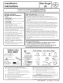
TOOLS YOU
WILL NEED
(x2)
10"ADJUSTABLEWRENCHES
, ic................._)
8"PIPEWRENCH LEVEL
SLIPJOINTPLIERS FLATBLADESCREWDRIVER
)
MATERIALSYOUWILLNEED
4"DIA.METALDUCT I====_
(RECOMMENDED)
4"DIAMMETALELBOW
4"DIA.FLEXIBLEMETAL(SEMI-RIGID)
ULLISTEDTRANSITIONDUCT
(IFNEEDED)
KITWXO8X10077(INCLUDES2ELBOWS)
4"DIA.FLEXIBLEMETAL(FOILTYPE)
ULLISTEDTRANSITIONDUCT
(IFNEEDED.)
Step 1Verify Your Gas Installation (see section 2).
Step 2 Prepare the Area and Exhaust for Installation of
New Dryer (see section 1).
Step ] Check and Insure the Existing External Exhaust is
Clean (see section 1) and Meets Attached Installation
Specifications (see section 6).
Step 4 Remove the Foam Shipping Pads (see section 1).
Step 5 Move the Dryer to the Desired Location.
Step 6 Level Your Dryer (see section 8).
Step 7 Connect the Gas Supply (see section ]) and check for
leaks (see section 4).
PIPE
SOAPSOLUTION
FORLEAKDETECTION
EXHAUSTHOOD COMPOUND
4"DUCTCLAMPS DUCTTAPE
OR SAFETYGLASSES
4"SPRINGCLAMPS
FLEXIBLEGASLINECONNECTOR GLOVES
Step 8 Connect the External Exhaust (see section 7).
Step 9 Connect the Power Supply (see section 5).
Step 10 Check the Operation of the Power Supply, Gas
Connections, and Venting.
Step 11 Place the Owner's Manual and the Installation
Instructions in a location where they will be noticed
by the owner.
For Alcove or Closet Installation see section 9.
For Bathroom or Bedroom Installation see section 10.
For Mobile or Manufactured Home see section 11.
For garage installation (if allowed by local codes), see section 12.
234D1582PO03 31-16225-2 03-12 GE

Installation Instructions
Minimum Clearance Other Than Alcove or Closet Installation
Minimum clearance to combustible surfaces and for air opening are: 0 in. clearance both sides and J_in. rear.
Consideration must be given to provide adequate clearance for installation and service.
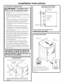
[] PREPARING FOR INSTALLATION
OF NEW DRYER
TIP:Install your dryer before installing your washer.
This will allow better access when installing dryer
exhaust.
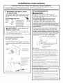
DISCONN_TING GAS
TURNGAS
SHUT-OFFVALVE1(7_ DISCONNECTANDDISCARDOLD
_u FLEXIBLEGASCONNECTORAND
TOTHEOFF
POSITION.x'_ _--_ OLDTRANSITIONDUCTING
MATERIAL,REPLACEWITHNEW
CSA(AGA)APPROVEDFLEXIBLE
GASLINECONNECTORANDUL
APPROVEDTRANSITIONDUCT.
WARNING - NEVERREUSEOLD
FLEXIBLE CON NECTORS.
The use of old flexible connectors can cause leaks
and personal injury. Always use new flexible connec-
tors when installing gas appliances.
REMOVING LINT FROM WALL
EXHAUST OPENING
• Remove and discard existing plastic or metal foil
transition duct and replace with UL listed transition
duct.
WALL
INTERNALDUCT
CHECKTHATEXHAUST
OPENING HOODDAMPEROPENS
ANDCLOSESFREELY.
TILTTHE DRYERSIDEWAYS
AND REMOVETHE FOAM
SHIPPING PADS BY
PULLING ATTHE SIDES
AND BREAKING THEM
AWAY FROM THE DRYER
LEGS.BE SURETO
REMOVEALL OFTHE
FOAM PIECESAROUND
THE LEGS.
[] GAS REQUIREMENTS
tLWARNING
Installation must conform to local codes and
ordinances, or in their absence, the NATIONAL FUEL
GASCODE,ANSI Z223.
This gas drger is equipped with a Valve & Burner
Assemblg for use onlg with natural gas. Using
conversion kit WE25X0217, gour local service
organization can convert this drger for use with
propane (LP)gas. ALL CONVERSIONSMUSTBEMADE BY
PROPERLYTRAINEDAND QUALIFIEDPERSONNELAND
IN ACCORDANCEWITH LOCALCODESAND ORDINANCE
REQUIREMENTS.
The dryer must be disconnected from the gas supply
piping system during any pressure testing of that
system at a test pressure in excess of O.5PSI(3.4 KPa).
The dryer must be isolated from the gas supply piping
system bg closing the equipment shut-off valve during
ang pressure testing of the gas supply piping of test
pressure equal to or less than 0.5 PSI(3.4 KPa).
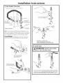
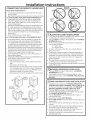
DRYERGASSUPPLYCONNECTION
A 2-5/8" 3/8"NPTMALETHREADGASSUPPLY
NOTE:Addtoverticaldimension
thedistancebetweencabinet
bottomtofloor.
;AS SUPPLY
A 1/8-in.National PipeTaper thread plugged tapping,
accessible for test gauge connection, must be installed
immediately upstream of the gas supply connection to
the dryer. Contact your local gas utility should you have
questions on the installation of the plugged tapping.
Supply line isto be 1/2-in. rigid pipe and equipped with
an accessible shut-off within 6ft. of, and in the same
room with the dryer.
Use pipe thread sealer compound or Teflon tape appro-
priate for natural or LPgas.
You must use with this dryer a flexible metal connector
listed connector ANSIZ21.24/CSA 6.10. The length of the
connect shall not exceed 3 ft.
Connect flexible metal connector to dryer and gas supply.
Open shut-off valve.
ADJUSTING FOR ELEVATION
• Gasclothes dryers input ratings are based on sea level
operation and need not be adjusted for operation at or
below 2000 ft. elevation.
For operation at elevations above 2000 ft., input ratings
should be reduced at a rate of 4 percent for each lO00
ft. above sea level.
• Installation must conform to local codes and ordinances or,
in their absence,the NATIONALFUELGASCODE,ANSIZ223.
2

Installation Instructions
IYI RECONNECTING GAS
Listed connector ANSt Z21.24 / CSA 6.10
1/8" NPT PIPE
NEW METAL PLUG FOR
GAS
FLEXIBLEGAS INLETPRESSURE
LINECONNECTOR
ADAPTER
ELBOW
3/8" NPT
SHUT-OFF
PIPE SIZE
ITEMSNOT SUPPLIED _AT LEAST1/2"
Note: The connector and fittings are designed for use
only on the original installation and are not to be reused
for another appliance or at another location. Keep flare
end of adaptor free of grease, oil and thread sealant.
CAUTION: Useadapters as shown. Connector
nuts must not be connected directly to pipe threads.
APPLYPIPECOMPOUND
TOTHEADAPTERAND
DRYERGASINLET.
GASLINEUSINGTWO_ I
TIGHTENTHE FLEXIBLE"_
ADJUSTABLEWRENCHE& _
APPLYPIPECOMPOUND
TOALLMALETHREADS.
TIGHTEN ALL CONNECTIONS
USINGTWO ADJUSTABLE WRENCHES.
DO NOT OVERTORQUE GAS CONNECTIONS!
I%-1LEAK TEST
WARNING: NEVERUSEANOPEN
FLAME TO TEST FOR GAS LEAKS.
OPEN
GASVALVE.
Check all connections for teoks with soopg solution or equivalent.
Apptg soap solution. Leek test solution must not contain ammo-
niawhich couldcause damage to the brassfittings.IfleaksGre
found, close v(]lve, retighten the joint, and repeat the soap test.
3

Installation Instructions
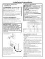
[] ELECTRICAL CONNECTION
INFORMATION
WARNING - TOREDUCETHE
RISK OF FIRE, ELECTRICAL SHOCK,
AND PERSONAL INJURY:
• DO NOT USEAN EXTENSIONCORDORAN ADAPTER
PLUGWITH THISAPPLIANCE.
Dryer must be electrically grounded in accordance
with local codes and ordinances, or in the absence
of local codes, in accordance with the NATIONAL
ELECTRICALCODE,ANSI/NFPANO.70.
ELECTRICAL REQUIREMENTS
This appliance must be supplied with 120V,60Hz, and
connected to a properly grounded branch circuit,
protected by a 15- or 20- amp circuit breaker or time-
delay fuse. If electrical supply provided does not meet the
above specifications, it is recommended that (] licensed
electrician install an approved outlet.
WARNING - THISDRYERIS
EQUIPPED A THREE-PRONG (GROUNDING)
PLUG FOR YOUR PROTECTION AGAINST
SHOCK HAZARD AND SHOULD BE PLUGGED
DIRECTLY INTO A PROPERLY GROUNDED
THREE-PRONG RECEPTACLE. DO NOT CUT
OR REMOVE THE GROUNDING PRONG FROM
THIS PLUG.
ENSUREPROPERGROUND
EXISTSBEFOREUSE.
IF LOCAL CODES PERMIT,
AN EXTERNAL GROUND WIRE
(NOT PROVIDED), WHICH MEETS
LOCAL CODES, MAY BE ADDED
BYATTACHING TO THE GREEN
GROUND SCREW ON THE REAR
OF THE DRYER, AND TO A GROUNDED
METAL COLD WATER PIPE OR OTHER
ESTABLISHED GROUND.
4
I-_ EXHAUST INFORMATION
WARNING -IN CANADA AND IN THE
UNITED STATES,THE REQUIRED EXHAUST DUCT
DIAMETER IS4 IN (102mm). DO NOT USEDUCT
LONGER THAN SPECIFIED IN THE EXHAUST
LENGTH TABLE.
Usingexhaustlongerthan specifiedlengthwill:
increasethedryingtimesand theenergycost.
Reducethe dryerlife.
• Accumulatelint, creatingapotential firehazard.
Thecorrect exhaustinstallation isYOURRESPONSIBILITY.
Problemsdueto incorrect installation are not covered by
the warranty.
Removeanddiscardexistingplasticor metalfoil transition
duct and replacewith ULlistedtransition duct.
TheMAXIMUMALLOWABLEduct lengthand numberof
bendsof theexhaustsystemdependsuponthetype of duct,
numberofturns,thetype of exhausthood (wallcap),and all
conditionsnotedbelow.Themaximumduct lengthfor rigid
metal duct isshownin thetable below.
EXHAUST LENGTH
RECOMMENDED MAXIMUM LENGTH
Exhaust Hood Types
Recommended
Use only for short
run installations
4" DIA
.......II-.
Rigid,
Metal
90 Feet
60 Feet
45 Feet
35 Feet
No. of 90° Rigid,
Elbows Hetal
0 60 Feet
1 45 Feet
2 35 Feet
3 25 Feet
EXHAUST SYSTEM CHECK LIST
HOOD ORWALL CAP
• Terminatein a mannerto preventback draftsor entry of birds
or otherwildlife.
• Terminationshouldpresentminimal resistanceto the exhaust
air flow and shouldrequirelittleor nomaintenanceto prevent
clogging.
•Never installa screenin or overtheexhaustduct.Thiscould
causelint buildup.
• Wallcapsmust beinstalledat least12in.abovegroundlevel
or anyother obstructionwiththe openingpointeddown.
SEPARATIONOFTURNS
Forbest performance,separateallturnsbyat least4 ft. of
straightduct, includingdistancebetweenlastturn and exhaust
hood.
TURNSOTHERTHAN900
• Oneturn of 450or lessmaybeignored.
• Two450turns shouldbetreatedasone 900turn.
• Eachturn over450shouldbetreatedasone 900turn.
SEALINGOFJOINTS
•Alljoints shouldbetight to avoidleaks.Themaleendof each
sectionofduct must pointawayfrom thedryer.
•Donotassembletheductwork with fastenersthat extend into
the duct.Theywill serveasa collectionpointfor lint.
•Ductjoints canbe madeair and moisture-tightbywrapping
the overlappedjoints with duct tape.
•Horizontal runs should slope down toward the outdoors
1/4 inch per foot.
INSULATION
Ductwork that runsthroughan unheatedareaor isnear air
conditioningshouldbeinsulatedto reducecondensationand
lintbuild-up.

Installation Instructions
r-71EXHAUST CONNECTION
WARNING - TOREDUCETHE
RISK OF FIRE OR PERSONAL INJURY:
• This clothes dryer must be exhausted to the
outdoors.
• We recommend that you install your dryer before
installing your washer. This will permit direct access
for easier exhaust connection.
• Use only 4" rigid metal ducting for the home exhaust
duct.
• Use only 4" rigid metal or UL-listed flexible metal
(semi-rigid or foil-type) duct to connect the dryer
to the home exhaust duct. It must be installed
in accordance with the instructions found in
"Connecting The Dryer To House Vent" on page 6 of
this manual.
• Do not terminate exhaust in a chimney, a wall,
a ceiling, gas vent, crawl space, attic, under an
enclosed floor, or in any other concealed space
of a building. The accumulated lint could create a
potential fire hazard.
• Never terminate the exhaust into a common duct
with a kitchen exhaust system. A combination of
grease and lint creates a potential fire hazard.
• Do not use duct longer than specified in the exhaust
length table. Longer ducts can accumulate lint,
creating a potential fire hazard.
• Never install a screen in or over the exhaust duct.
This will cause lint to accumulate, creating a
potential fire hazard.
• Do not assemble ductwork with any fasteners
that extend into the duct. These fasteners can
accumulate lint, creating a potential fire hazard.
• Do not obstruct incoming or exhausted air.
• Provide an access for inspection and cleaning of
the exhaust system, especially at turns and joints.
Exhaust system shall be inspected and cleaned at
least once year.
THIS DRYER COMES READY FOR REAR
EXHAUSTING. IF SPACE IS LIMITED, USE
THE INSTRUCTIONS IN SECTION 9 TO
EXHAUST DIRECTLY FROM THE SIDES OR
BOTTOM OF THE CABINET.
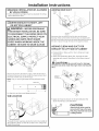
STANDARD REAR EXHAUST
(Vented ot floor level)
FORSTRAIGHTLINEINSTALLATION,CONNECTTHEDRYEREXHAUSTTO
THEEXTERNALEXHAUSTHOODUSINGDUCTTAPEORCLAMR
CSA(AGA)APPROVED
NEWFLEXIBLEGAS
LINECONNECTOR
GAS
EXTERNAL
INLET
DUCT
PIPE
OPENING
DUCTTAPEOR
DUCTCLAMP
4" METALDUCT
(CUTTOPROPER
LENGTH) DUCTTAPEOR
DUCTCLAYP
NOTE:WE STRONGLYRECOMMENDSOLIDMETALEXHAUSTDUCTING.
HOWEVER,IF FLEXIBLEDUCTINGIS USEDITMUSTBEUL-LISTEDMETAL
NOTPLASTIC.
(
ELBOWHIGHLY
RECOMMENDED-
STANDARD REAR EXHAUST
(Vented above floor level}
ELBOWHIGHLY
_ RECOMMENDED
m r'--
RECOMMENDED
CONFIGURATION
TOMINiMiZE
EXHAUST
BLOCKAGE.
NOTE: ELBOWS WILL PREVENT DUCT
KINKING AND COLLAPSING.
[] LEVELING DRYER
LEVEL
FRONT-TO-BACK.
LEVEL
SIDE-TO-SIDE.
4LEVELINGLEGS
STANDTHEDRYERUPRIGHTNEARTHE
FINALLOCATIONANDADJUSTTHE4LEVELING
LEGSTOMATCHTHEHEIGHTOFYOURWASHER.
ADJUSTTHE2ANTI-TIPLEGSTOCONTACT
THEFLOOR.
2ANTI-TIPLEGS
5

Installation Instructions
CONNECTING THE DRYERTO HOUSE VENT
RIGID METALTRANSITION DUCT
• Forbestdrying performance,a rigid metaltransitionduct is
recommended.
• Rigidmetaltransitionsductsreducetheriskofcrushingandkinking.
UL-LISTEDFLEXIBLEMETAL(SEMI-RIGIDTRANSITIONDUCT
• If rigid metalductcannot be used,then UL-listedflexible
metal(semi-rigid)ducting canbe used(KitWX08XZ0077).
• Neverinstallflexiblemetal duct in walls,ceilings,floorsor
otherenclosedspaces.
• Totallengthofflexiblemetalductshouldnotexceed8feet(2.4m).
• Formany applications,installingelbowsat boththedryer
andthe wallishighlyrecommended(seeillustrationsbelow).
Elbowsallowthe dryerto sit closeto thewallwithout kinking
andor crushingthetransition duct,maximizingdrying
performance.
• Avoidrestingthe duct on sharpobjects.
UL-LISTEDFLEXIBLEMETAL(FOIL-TYPE)TRANSITION DUCT
° Inspecialinstallations,it may benecessaryto connectthe
dryertothe housevent usingaflexiblemetal(foiltype)duct.
A UL-listedflexiblemetal(foil-type)ductmay beusedONLY
ininstallationswhererigidmetalorflexiblemetal(semi-rigid)
ductingcannotbeusedANDwherea4" diametercanbe
maintainedthroughoutthe entirelengthofthetransitionduct.
• InCanadaand the UnitedStates,onlytheflexible metal(foil-
type)ductsthat complywith the"Outlinefor ClothesDryer
TransitionDuctSubject2158A"shallbe used.
• Neverinstallflexiblemetal duct in walls,ceilings,floorsor
otherenclosedspaces.
• Totallengthofflexiblemetalductshouldnotexceed8feet(2.4m).
• Avoidrestingthe duct on sharpobjects.
• Forbestdrying performance:
Z.Slideone endof theduct overthe clothesdryeroutlet
pipe.
2.Securethe duct with a clamp.
3.With the dryerin its permanentposition,extendthe duct
to its full length.Allow2" ofduct to overlaptheexhaust
pipe.Cutoff and removeexcessduct. Keeptheduct as
straightaspossiblefor maximumairflow.
4.Securethe duct to theexhaustpipewith the otherclamp.
ELBOWHIGHLY
RECOMMENDED
_WS HIGHLY
- RECOMMENDE_
DO
EXCESSIVE
EXHAUST
LENGTH
(
[ ,LCOVE OR CLOSETINSTALLATION
• If yourdryerisapprovedfor installationin an alcoveor closet,
it will bestatedon a labelon thedryer back.
• ThedryerMUSTbe ventedto theoutdoors.Seethe EXHAUST
INFORMATIONsection.
• Minimumclearancebetween dryercabinet and adjacent
wallsor other surfacesis:
0in.eitherside
3in.front and rear
• Minimumvertical spacefrom floor to overheadcabinets,
ceiling,etc.is52 in.
• Closetdoorsmust beIouveredor otherwiseventilatedand
mustcontain a minimumof 60 sq.in.of openareaequally
distributed.Ifthe closetcontainsboth a washeranda dryer,
doorsmustcontain a minimumof 120sq.in,of openarea
equallydistributed.
• Theclosetshouldbeventedto the outdoorsto preventgas
pocketingincaseof agasleakinthe supplyline.
• Nootherfuel-burningapplianceshallbe installedin the same
closetwith the dryer.
[i--O]BATHROOM OR BEDROOM INSTALLATION
• ThedryerMUSTbe ventedtothe outdoors.SeeEXHAUST
INFORMATIONsection6.
• Theinstallationmustconformwith localcodesor,in the
absenceof localcodes,with the NATIONALFUELGASCODE,
ANSIZ223.
[_]MOBILE OR MANUFACTUREDHOME INSTALLATION
• Installationmustconform tothe MANUFACTUREDHOME
CONSTRUCTION& SAFETYSTANDARD,TITLE24,PART32-80
or,whensuchstandard isnotapplicable,with AMERICAN
NATIONALSTANDARDFORMOBILEHOME,NO.501B.
• ThedryerMUSTbe ventedto theoutdoorswith the
termination securelyfastenedto the mobilehomestructure.
(SeeEXHAUSTINFORMATIONsection6.)
• Thevent MUSTNOTbeterminated beneatha mobileor
manufactured home.
• Thevent duct material MUSTBEMETAL.
• KIT14-D346-33MUSTbe usedto attachthe dryersecurelyto
the structure.
• Thevent HUSTNOTbeconnectedto anyother duct,vent,or
chimney.
• Donot usesheetmetal screwsor other refasteningdevices
which extendintothe interiorof theexhaustvent.
• Providean openingwith a freeareaof at least25sq.in.or
introductionof outsideair intothe dryerroom.
• Stackingofa gasdryerisnot permittedin a mobilehomeor
manufactured home.
6

Installation Instructions
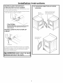
I_IGARAGE INSTALLATION (IF ALLOWED
BY LOCAL CODES)
• Dryers installed in garages must be elevated 18 inches
(46cm) above the floor.
IT3-1DRYEREXHAUST TO RIGHT, LEFT
OR BOTTOM CABINET
WARNING - BEFOREPERFORMING
THIS EXHAUSTINSTALLATION, BE SURE
TO DISCONNECT THE DRYER FROM ITS
ELECTRICAL SUPPLY. PROTECT YOUR
HANDS AND ARMS FROM SHARP
EDGES WHEN WORKING INSIDE THE
CABINET. BE SURE TO WEAR GLOVES
REMOVE
SCREW
ANDSAVE.
REMOVE,_)
DESIRED
KNOCKOUT
lONEONLY).
Detach and remove the bottom, right or left side knockout
as desired. Remove the screw inside the drger exhaust duct
and save. Pull the duct out of the drger.
Note: Onlg 4" round rigid metal ducting allowed inside
drger.
FIXINGHOLE
B A
9"
Cut the duct as shown and keep portion A.
TAB LOCATION
BENDTAB
UP45o
Through the rear opening, locate the tab in the middle of
the appliance base. Lift the tab to about/450 using a flat
blade screwdriver.
ADDING NEW DUCT
FIXING
HOLE
PORTION"A"
LEFTSIDE
EXHAUST
Reconnectthe cut portion (A)of the duct to the blower
housing. Makesurethat the shortened duct isaligned with
the tab inthe base.Usethe screw saved previouslgto secure
the duct in placethrough the tab on the appliance base.
ADDING ELBOW AND DUCT FOR
EXHAUST TO LEFT SIDE OF CABINET
• Preassemble 4" elbow with 4" duct. Wrap duct tape
around joint.
• Insert duct assembly, elbow first, through the side
opening and connect the elbow to the dryer internal
duct.
CAUTION: Be sure not to pullor damage
theelectricalwiresinsidethedryerwhen insertingthe
duct.
BEADDEDTO _!I/ -:Sj_j _Mf
EXHAUSTCAN __ __
LEFTORR]GHTSIDE _
• Apply duct tape as shown on the joint between the
dryer internal duct and the elbow.
DUCT
,TAPE
CAUTION:
Internal duct joints must be
secured with tape, otherwise
they may separate and cause
a safetg hazard.
7

Installation Instructions
ADDING ELBOW FOR EXHAUST
THROUGH BOTTOM OF CABINET
• Insert the elbow through the rear opening and connect
it to the dryer internal duct.
• Apply duct tape on the joint between the dryer internal
duct and elbow, as shown on page 7.
CAUTION:
Internal duct joints must be secured with tape,
otherwise they may separate and cause a
safety hazard.
ADDING COVER PLATE TO REAR OF
CABINET
PLATE
(KITWEII454)
Connect standard metal elbows and ducts to complete
the exhaust system. Cover back opening with a plate (Kit
WEllV1454)available from your local service provider.
Placedryer in final location.
WARNING-NEVER LEAVE THE BACK
OPENING WITHOUT THE PLATE.
[] CHANGING DIRECTION OF DOOR
OPENING
REMOVE4
HINGESCREWS.
REMOVE4 HOLEPLUGSAND
PLACETHEMINTHEHOLES
ONTHEOPPOSITESIDE.
ROTATEDOOR1800
AND REINSTALL.
8

Installation Instructions
1_ CONNECTING INLET HOSES
(on some models)
To produce steam, the dryer must connect to the cold
water supply. Since the washer must also connect to the
cold water, a "Y"connector isinserted to allow both inlet
hoses to make that connection at the same time.
NOTE: Usethe new inlet hoses provided; never
use old hoses.
1.Turn the cold water faucet off. Remove the washer inlet
hose from the washer fill valve connector (cold).
2. Ensurethe rubber fiat washer isin place and screw the
female coupling of the short hose onto the washer fill
valve connector. Tighten by hand until firmly seated.
3. Attach the female end of the "Y"connector to the
male coupling of the short hose. Ensurethe rubber fiat
washer is in place. Tighten by hand until firmly seated.
4. Insert the filter screen in the coupling of the washer's
inlet hose. If a rubber flat washer isalready in place
remove it before installing the filter screen. Attach this
coupling to one male end of the "Y" connector. Tighten
by hand until firmly seated.
5. Ensurethe rubber fiat washer isin place and attach the
dryer's long inlet hose to the other male end of the "Y"
connector. Tighten by hand until firmly seated.
6. Ensurethe rubber fiat washer isin place and attach
the other end of the dryer's long inlet hose to the fill
valve connector at the bottom of the dryer back panel.
Tighten by hand until firmly seated.
7. Using pliers, tighten all the couplings with an additional
two-thirds turn.
NOTE: Donot overtighten. Damage to the couplings may
result.
[] CONNECTING INLET HOSES (cont.)
8.Turn the water fauceton.
9. Check for leaks around the "Y" connector, faucet and
hose couplings.
WATER SUPPLY REQUIREMENTS
Hot and cold water faucets IvlUSTbe installed within 42
in. (107 cm) of your wosher's water inlet. The faucets
IvIUSTbe 3/4 in. (1.9cm) garden hose-type so inlet hoses
con be connected. Water pressure IvIUSTbe between 10
and 120 pounds per square inch. Your water department
con advise you of your water pressure.
NOTE:A water softener is recommended to reduce
buildup of scale inside the steam generator if the home
water supply isvery hard.
I-i-61SERVICING
WARNING- LABEL ALL WIRES
PRIOR TO DISCONNECTION WHEN
SERVICING CONTROLS. WIRING ERRORS
CAN CAUSE IMPROPER AND DANGEROUS
OPERATION AFTER SERVICING/
INSTALLATION.
Forservicing phone numbers for replacement parts, and
other information, refer to Owner's Manual or visit our
Web site.
REGISTERYOUR NEW APPLIANCE TO RECEIVEANY
IMPORTANT PRODUCT NOTIFICATIONS.
Pleose go to www.GEAppliunces.com or moil in your
Product Registrotion Cord.
For questions on installation, coil:800.626.2000 (US)or
800-561-3344 (Canada).
9

Notes
10

Notes
1!
-
 1
1
-
 2
2
-
 3
3
-
 4
4
-
 5
5
-
 6
6
-
 7
7
-
 8
8
-
 9
9
-
 10
10
-
 11
11


GE HTDX100GM1WW Installation guide
- Category
- Sanitary ware
- Type
- Installation guide
Ask a question and I''ll find the answer in the document
Finding information in a document is now easier with AI
Related papers
-
GE DCCD330EDWC Installation guide
-
-
-
-
GE GHDP490EF2WW Installation guide
-
-
GE HTDX100EM3WW Installation guide
-
GE WSM2780HWW User manual
-
-
Other documents
-
Samsung DV45H6300EW/A3-00 Owner's manual
-
Samsung DV42H5000EW/A3-01 User manual
-
Miele T9820 Owner's manual
-
 T & S Brass & Bronze Works 050A Datasheet
-
Hotpoint HTDX100EM4WW Installation guide
-
-
Kenmore 11076702691 Owner's manual
-
Everbilt EZCNHD Operating instructions
-
Whirlpool WGD85HEFW1 Installation guide
-
