Page is loading ...

VN8900Interface Family
Manual
Version 6.0|English

Imprint
Vector Informatik GmbH
Ingersheimer Straße 24
D-70499 Stuttgart
The information and data given in this user manual can be changed without prior notice. No part of this manual may be reproduced in any
form or by any means without the written permission of the publisher, regardless of which method or which instruments, electronic or
mechanical, are used. All technical information, drafts, etc. are liable to law of copyright protection.
© Copyright 2017, Vector Informatik GmbH. All rights reserved.

Contents
VN8900 Interface Family Manual Version 6.0 3
Contents
1 Introduction 5
1.1 About this User Manual 6
1.1.1 Certification 7
1.1.2 Warranty 7
1.1.3 Registered Trademarks 7
1.2 Important Notes 8
1.2.1 Safety Instructions and Hazard Warnings 8
1.2.1.1 Proper Use and Intended Purpose 8
1.2.1.2 Hazards 9
1.2.1.3 Disclaimer 9
1.2.2 GRUB Version 0.4.4-r61 10
1.2.3 AutoLaunch V310 10
2 VN8900 Interface Family 11
2.1 System Description 12
2.1.1 Introduction 12
2.1.2 Real Time Processing 14
2.1.3 Stand-Alone Mode 14
2.1.4 Network Extension 15
2.2 Base Modules 16
2.2.1 VN8911 Base Module 16
2.2.2 VN8914 Base Module 22
2.2.3 VN8912 / VN8912A Base Module 28
2.3 Plug-In Module 32
2.3.1 VN8970 FlexRay/CAN/LIN Module 32
2.3.2 VN8972 FlexRay/CAN/LIN Module 44
2.4 Accessories 56
2.5 Mounting of Plug-In Modules and Piggybacks 57
3 Getting Started 60
3.1 Driver Installation 61
3.2 Driver Installation on the Device 63
3.3 Device Configuration 64
3.4 Loop Tests 65
3.4.1 CAN 65
3.4.2 FlexRay 67
4 Vector Hardware Configuration 68


1 Introduction
VN8900 Interface Family Manual Version 6.0 5
1 Introduction
In this chapter you find the following information:
1.1 About this User Manual 6
1.1.1 Certification 7
1.1.2 Warranty 7
1.1.3 Registered Trademarks 7
1.2 Important Notes 8
1.2.1 Safety Instructions and Hazard Warnings 8
1.2.2 GRUB Version 0.4.4-r61 10
1.2.3 AutoLaunch V310 10

1 Introduction
VN8900 Interface Family Manual Version 6.0 6
1.1 About this User Manual
Conventions In the two following charts you will find the conventions used in the user manual
regarding utilized spellings and symbols.
Style Utilization
bold Blocks, surface elements, window- and dialog names of the soft-
ware. Accentuation of warnings and advices.
[OK]
File|Save
Push buttons in brackets
Notation for menus and menu entries
Microsoft Legally protected proper names and side notes.
Source Code
File name and source code.
Hyperlink Hyperlinks and references.
<CTRL>+<S> Notation for shortcuts.
Symbol Utilization
This symbol calls your attention to warnings.
Here you can obtain supplemental information.
Here you can find additional information.
Here is an example that has been prepared for you.
Step-by-step instructions provide assistance at these points.
Instructions on editing files are found at these points.
This symbol warns you not to edit the specified file.

1 Introduction
VN8900 Interface Family Manual Version 6.0 7
1.1.1 Certification
Certified Quality
Management System
Vector Informatik GmbH has ISO 9001:2008 certification. The ISO standard is a glob-
ally recognized standard.
1.1.2 Warranty
Restriction
of warranty
We reserve the right to change the contents of the documentation and the software
without notice. Vector Informatik GmbH assumes no liability for correct contents or
damages which are resulted from the usage of the documentation. We are grateful for
references to mistakes or for suggestions for improvement to be able to offer you
even more efficient products in the future.
1.1.3 Registered Trademarks
Registered
trademarks
All trademarks mentioned in this documentation and if necessary third party
registered are absolutely subject to the conditions of each valid label right and the
rights of particular registered proprietor. All trademarks, trade names or company
names are or can be trademarks or registered trademarks of their particular pro-
prietors. All rights which are not expressly allowed are reserved. If an explicit label of
trademarks, which are used in this documentation, fails, should not mean that a name
is free of third party rights.
> Windows, Windows 7, Windows 8.1, Windows 10
are trademarks of the Microsoft Corporation.
> and
are trademarks of the SD Card Association.

1 Introduction
VN8900 Interface Family Manual Version 6.0 8
1.2 Important Notes
1.2.1 Safety Instructions and Hazard Warnings
Caution!
In order to avoid personal injuries and damage to property, you have to read and
understand the following safety instructions and hazard warnings prior to installation
and use of this interface. Keep this documentation (manual) always near the inter-
face.
1.2.1.1 Proper Use and Intended Purpose
Caution!
The interface is designed for analyzing, controlling and otherwise influencing control
systems and electronic control units. This includes, inter alia, bus systems like
CAN, LIN, K-Line, MOST, FlexRay, Ethernet, BroadR-Reach and/or ARINC 429.
The interface may only be operated in a closed state. In particular, printed circuits
must not be visible. The interface may only be operated (i) according to the instruc-
tions and descriptions of this manual; (ii) with the electric power supply designed for
the interface, e.g. USB-powered power supply; and (iii) with accessories man-
ufactured or approved by Vector.
The interface is exclusively designed for use by skilled personnel as its operation
may result in serious personal injuries and damage to property. Therefore, only
those persons may operate the interface who (i) have understood the possible
effects of the actions which may be caused by the interface; (ii) are specifically
trained in the handling with the interface, bus systems and the system intended to
be influenced; and (iii) have sufficient experience in using the interface safely.
The knowledge necessary for the operation of the interface can be acquired in work-
shops and internal or external seminars offered by Vector. Additional and interface
specific information, such as „Known Issues“, are available in the „Vector Know-
ledgeBase“on Vector´s website at www.vector.com. Please consult the „Vector
KnowledgeBase“for updated information prior to the operation of the interface.

1 Introduction
VN8900 Interface Family Manual Version 6.0 9
1.2.1.2 Hazards
Caution!
The interface may control and/or otherwise influence the behavior of control sys-
tems and electronic control units. Serious hazards for life, body and property may
arise, in particular, without limitation, by interventions in safety relevant systems
(e.g. by deactivating or otherwise manipulating the engine management, steering,
airbag and/or braking system) and/or if the interface is operated in public areas (e.g.
public traffic, airspace). Therefore, you must always ensure that the interface is
used in a safe manner. This includes, inter alia, the ability to put the system in
which the interface is used into a safe state at any time (e.g. by „emergency shut-
down“), in particular, without limitation, in the event of errors or hazards.
Comply with all safety standards and public regulations which are relevant for the
operation of the system. Before you operate the system in public areas, it should be
tested on a site which is not accessible to the public and specifically prepared for
performing test drives in order to reduce hazards.
1.2.1.3 Disclaimer
Caution!
Claims based on defects and liability claims against Vector are excluded to the
extent damages or errors are caused by improper use of the interface or use not
according to its intended purpose. The same applies to damages or errors arising
from insufficient training or lack of experience of personnel using the interface.

1 Introduction
VN8900 Interface Family Manual Version 6.0 10
1.2.2 GRUB Version 0.4.4-r61
Copyright and
disclaimer
The product contains the software GRUB Version 0.4.4-r61. Copyright (C) 1989,
1991 Free Software Foundation, Inc. 59 Temple Place, Suite 330, Boston, MA 02111-
1307 USA. This program is free software; you can redistribute it and/or modify it
under the terms of the GNU General Public License as published by the Free Soft-
ware Foundation, version 2 of the License. This program is distributed by the holder of
the Copyright in the hope that it will be useful, but WITHOUT ANY WARRANTY by
the holder of the Copyright; without even the implied warranty of
MERCHANTABILITY or FITNESS FOR A PARTICULAR PURPOSE. See the
GNU General Public License for more details.
Reference
The GNU GENERAL PUBLIC LICENSE can be found in the separate text file
manual on the Vector Driver Disk in \Documentation\Licenses.
Source code The product contains the software GRUB Version 0.4.4-r61. We will send anyone a
complete machine-readable copy of the corresponding source code by email without
any charge if so requested by writing to support@vector.com. This offer is valid for
three years starting at the time you received the product.
1.2.3 AutoLaunch V310
Copyright and
disclaimer
The product contains the software AutoLaunch V310. Copyright (c) 2011 Samuel
Phung (Embedded101.com). Permission is hereby granted, free of charge, to any per-
son obtaining a copy of this software and associated documentation files (the "Soft-
ware"), to deal in the Software without restriction, including without limitation the
rights to use, copy, modify, merge, publish, distribute, sublicense, and/or sell copies
of the Software, and to permit persons to whom the Software is furnished to do so,
subject to the following conditions: The above copyright notice and this permission
notice shall be included in all copies or substantial portions of the Software.

2 VN8900 Interface Family
VN8900 Interface Family Manual Version 6.0 11
2 VN8900 Interface Family
In this chapter you find the following information:
2.1 System Description 12
2.1.1 Introduction 12
2.1.2 Real Time Processing 14
2.1.3 Stand-Alone Mode 14
2.1.4 Network Extension 15
2.2 Base Modules 16
2.2.1 VN8911 Base Module 16
2.2.2 VN8914 Base Module 22
2.2.3 VN8912 / VN8912A Base Module 28
2.3 Plug-In Module 32
2.3.1 VN8970 FlexRay/CAN/LIN Module 32
2.3.2 VN8972 FlexRay/CAN/LIN Module 44
2.4 Accessories 56
2.5 Mounting of Plug-In Modules and Piggybacks 57

2 VN8900 Interface Family
VN8900 Interface Family Manual Version 6.0 12
2.1 System Description
2.1.1 Introduction
Network interface
with real-time
computer
The VN8900 interface family is designed for high-performance applications in combi-
nation with CANoe/CANalyzer. The application areas include system simulations or
bypassing applications with Simulink, remaining bus simulations, gateway implemen-
tations, test executions (MiniHIL) or data monitoring.
Another key feature is the execution of time-critical CANoe/CANalyzer configurations
without any user PC and without any negative effects on functionality of the running
application.
User Desktop PC / Notebook
CANalyzer / CANoe / CANape
USB
VN8911
Real-time PC
Intel ATOM
VN8914
Real-time PC
Intel Core-i7
MiniHIL Control & Test Execution
Real-time Simulation and
Model Execution (CAPL, .NET, Simulink)
Measurement, Analysis, Logging
Bypassing
CAN
LIN
J1708
FlexRay
VN8970
VN8972
Up to 8 Channels for
FlexRay CAN/LIN/
J1708/K-Line
bus access
I/O Digital/Analog
IOpiggy8642
USB Host/Client
GbETH
Figure 1: Operator side (user PC) and measurement side

2 VN8900 Interface Family
VN8900 Interface Family Manual Version 6.0 13
Hardware flexibility Another important VN8900 product characteristic is the modularity of the network inter-
face, which lets users flexibly adapt it to the measurement environment and existing
buses. The overall system is comprised of these components:
> Base Module
Processor unit with memory for executing simulations and time-critical program
sections in stand-alone mode. The Base Module has an Intel processor and basic
port connections for power supply, synchronization, USB and Ethernet. You will
find further details on Base Modules beginning on page 16.
Figure 2: VN8914 back side
> Plug-In Module
The Plug-In Module represents the actual network interface; it provides the related
interfaces as plug connections (e.g. FlexRay, CAN, LIN or digital-analog in-
put/output). You will find additional details on Plug-In Modules beginning on page
32.
Figure 3: VN8914 with inserted VN8972 FlexRay/CAN/LIN Module

2 VN8900 Interface Family
VN8900 Interface Family Manual Version 6.0 14
> Piggybacks
Piggybacks establish the connection from the Vector network interface to the us-
er’s electrical networks via appropriate transceivers (FlexRay/CAN/LIN...). More-
over, the Piggyback usually offers the electrical isolation to protect the measure-
ment hardware as well as the system under test.
The amount and kind of supported Piggybacks varies between the Plug-In Mod-
ules. Please find the list of valid combinations in section "Transceiver Com-
patibility" of the accessories manual on the Vector Driver Disk in
\Documentation\Accessories.
Figure 4: Piggyback
2.1.2 Real Time Processing
General When requirements for timing precision are strict, the measurement hardware must be
able to operate with very low latency. The integrated processor of the VN8900 inter-
face family meets this standard and offers significantly improved latency times com-
pared to normal PCs.
CANoe The VN8900 interface family is a real-time hardware that is designed for using with
CANoe. CANoe offers the option of executing real-time relevant simulations and test
functions on the VN8900 – separate from the graphic user interface. On the one hand,
this increases overall system performance, and on the other it enables shorter latency
times and more precise timers. Configuration of the simulation and evaluation are per-
formed on a standard PC (CANoe), while the simulation and test kernel are executed
on the VN8900 (CANoeRT). Communication between the two computers is routed via
a USB cable or via Ethernet (see figure 1).
2.1.3 Stand-Alone Mode
CANoe configuration The VN8900 interface family offers a stand-alone mode which allows a measurement
without any additional user PC.
For this purpose a measurement application can be configured in CANoe, which is
then written into the permanent memory of the VN8900. After a restart, the configura-
tion is loaded and the measurement autonomously started.
start-up time
(see technical data)
power/
restart
start time
load user config
auto run measurement
loading time
(depends on config)
total boot-up time
Figure 5: Booting overview

2 VN8900 Interface Family
VN8900 Interface Family Manual Version 6.0 15
2.1.4 Network Extension
Additional
network channels
CANoe/CANalyzer supports a single Base Module at a time. To use more network
channels, the VN8900 interfaces offer additional USB (host) ports to connect to other
Vector network interfaces. Time synchronization of the different network interfaces
can be done via the sync line.
VN8911
USB (device)
CANoe / CANalyzer
User Desktop PC / Notebook
e. g. VN1640A
USB (host)
SYNCcable XL
Power
Figure 6: Extension example

2 VN8900 Interface Family
VN8900 Interface Family Manual Version 6.0 16
2.2 Base Modules
2.2.1 VN8911 Base Module
Description Base Module with integrated Intel Atom processor unit for running real-time appli-
cations. Connection to user networks is provided by a Plug-In Module with individual
bus transceivers (see section Plug-In Module on page 32).
The VN8911 also supports the Vector Tool Platform (VTP). With Extended Real Time
as a part of the Vector Tool Platform, the throughput, latency, and determinism of
CANoe and CANape are improved. To achieve this, the device is logically divided into
two areas. A new area provides Extended Real Time in which predefined functions
can be executed under real-time conditions.
Figure 7: VN8911 back and front side (with Plug-In Module)
Connections
Figure 8: VN8911 back side
> Keypad Start/Stop
This key instantly starts or stops a preconfigured CANoe measurement.
> Keypads F2/F3/F4
These keys can be assigned to CAPL functions.
> LED S1/S2
These LEDs offer a visual feedback for active measurements and can be indi-
vidually controlled via CAPL.

2 VN8900 Interface Family
VN8900 Interface Family Manual Version 6.0 17
> LEDRun
Multicolored channel LED which indicates the power up/down status.
Color Description
Off Power up/down control line not activated since reboot.
Green Device is running.
Red Inactive power up/down control line. Device shuts down into power-
down mode after time out (has to be defined in CANoe).
> LEDPower
Multicolored channel LED which indicates the power status.
Color Description
Off Power supply disconnected.
Green Power supply connected.
> ETH1/ETH2
These Ethernet ports can be used to connect other Vector Ethernet devices for
use with CANoe, CANalyzer or CANape. Currently supported: VX1121, VX1131,
VX1132, VX1135, VX1060. Furthermore, the Ethernet ports can be used to inter-
connect your host PC and the VN8911 to use them with measurement appli-
cations (e.g. CANoe, CANalyzer).
> USB 2.0/3.0 (host)
These USB ports can be used to connect other Vector USB devices for use with
CANoe or CANalyzer. The summarized output current at these ports is limited to
1050 mA.
Supported Device
Max. Number of Devices
externally powered USB powered
CANcaseXL / log 2 2
VN0601 not applicable 2
VN1630A / VN1640A not applicable 2
VN1630 log 2 2
VN2610/ VN2640 2 not applicable
VN3600 2 not applicable
VN5610 / VN5610A 2 *
VN5640 1 not applicable
VN7600 2 not applicable
VN7640 2 not applicable
* Depending on use-case.
Note
When using the USBhost connector, the Vector device has to be connected to
the VN8911 before powering the VN8911. Please ensure that the USB logo on
the USB cable is on the bottom side (USB pins at top) before connecting. Do not
force the cable into the USB connector to avoid mechanical damages.
> USB (device)
Interconnect your Host PC and the VN8911 via this USB 3.0 port to install the
device on the Host PC and to use it together with measurement applications (e.g.
CANoe, CANalyzer).

2 VN8900 Interface Family
VN8900 Interface Family Manual Version 6.0 18
> SD card slot
This slot can be used for recording use cases.
Recommended cards: Industrial Grade SD, SDHC or SDXC.
> Sync/Ctrl
This terminal (Binder type 711) can be used for time synchronization of different
Vector devices (see section Time Synchronization on page 74) or to control the
power up/down function of the device.
Pin Assignment
1 Power up/down control line
2 Synchronization line
3 Ground
3
1
2
Caution!
The power up/down control line uses the same reference to GND as the power
supply input of the device, not pin 3 of the sync/ctrl connector.
In order to use the power up/down function, switch off the device and remove the
Plug-In Module. Find the power up/down switch underneath the heat sink and set
it to ON.
Power up/down switch
ON
OFF
Figure 9: Power up/down switch in VN8911
Reassemble the Plug-In Module and connect the power supply. Depending on the
voltage at the power up/down control line, the VN8911 can be powered up or shut
down.
Ctrl Description
0 V If running, the device shuts down after time out (approx. 5 seconds).
Otherwise the device remains in power-up mode.
> 5 V If in power-down mode, the device powers up (please note the start-up
time in section Technical data on page 21). Current consumption in
power-down mode: 2.9mA, max.104mW@36 V.

2 VN8900 Interface Family
VN8900 Interface Family Manual Version 6.0 19
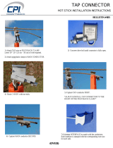
Example
With this wiring, the VN8911 powers up and down with the ignition switch of the
vehicle.
GND
Terminal 30
(battery)
Terminal 15
(battery through
ignition switch)
VN8911
Power Up/Down
Ctrl (pin 1)
Vehicle
Power
1
2
3
1
2
Level at terminal 15 / Power Up/Down Ctrl
[V]
5
0
device in
power-down
mode
at < 5V
t
ignition
switch on
device starts
at > 5 V
device in
power-down
mode
at < 5V
ignition
switch off
You can use the following Vector accessories to connect the VN8911 to the
vehicle:
> Power up/down control
Connection Cable Binder Type 711 (3-pin), part number 30011
> Power
ODU Connector / Bunch Plugs, part number 05069
> Power
For its power supply, the VN8911 has a two-pin ODU connector (MINI-SNAP
size1, type GG1L0C-P02RP00-0000). Attach the enclosed power cable to power
up the unit (matching ODU connector type S11L0C-P02NPL0-6200).
Pin Assignment
2 GND
1 +
1
2

2 VN8900 Interface Family
VN8900 Interface Family Manual Version 6.0 20
CFast card
Figure 10: CFast card slot in VN8911
The VN8911 operating system is stored on a CFast card and must not be removed dur-
ing operation.
Note
The CFast card should only be removed for system recoveries. Please contact the
Vector support for further instructions on system recoveries.
/