Page is loading ...

1© Munters Corporation, November 2019
QM1232r2
Instruction Manual
WS55 Exhaust Fan
Fiberglass w/ Plastic Cone - 1-Pack Quick Kit
Models: WS55xKxCP • WS55xKxGP • WS55xPxCP-PE •
WS55xPxCT-PE
WS55
Exhaust Fan
Fiberglass w/
Plastic Cone
1-Pack Quick Kit

© Munters Corporation, November 2019
2
QM1232r2
Thank You:
Thank you for purchasing a Munters WS55 Exhaust Fan. Munters equipment is designed to be the highest
performing, highest quality equipment you can buy. With the proper installation and maintenance it will provide
many years of service.
Please Note:
To achieve maximum performance and insure long life from your Munters product it is essential that it be installed
and maintained properly. Please read all instructions carefully before beginning installation.
Warranty:
For Warranty claims information see the “Warranty Claims and Return Policy” form QM1021 available from the
Munters Corporation office at 1-800-227-2376 or by e-mail at [email protected].
Conditions and Limitations:
• Products and Systems involved in a warranty claim under the “Warranty Claims and Return Policy” shall have
been properly installed, maintained and operated under competent supervision, according to the instructions
provided by Munters Corporation.
• Malfunction or failure resulting from misuse, abuse, negligence, alteration, accident or lack of proper installation
or maintenance shall not be considered a defect under the Warranty
.
WS55 Exhaust Fan; Fiberglass w/ Plastic Cone
Instructions for Use and Maintenance

3© Munters Corporation, November 2019
QM1232r2
Index
Chapters Page
1. Unpacking the Equipment 4
1.1 Parts List 4
1.2 Fan Dimensions 6
1.3 Tools for Installation 6
2. Installation Instructions 7
2.1 Wall Framing 7
2.2 Fan Assembly 8
2.3 Motor Mounting 10
2.4 Cone Installation 14
3. Electrical Wiring 20
3.1 Recommended Wire Routing 21
4. Operation 22
5. Maintenance 23
6. Winterizing 25
6.1 Winterizing 25
6.2 Winter Weather Protection 25
7. Troubleshooting 26
8. Exploded View and Parts List 28-29

© Munters Corporation, November 2019
4
QM1232r2
1.1 Parts List
Unpacking the Equipment
1.
Broiler Fan (WS55xK)
Each Crate Includes
1 – 55” Fiberglass Fan, Sub-Assembly
1 – Plastic Shutter
1 – Motor
4 – Cone Sections, PL
4 – Cone Support Brackets, PC Type, Galvanized
1 – Cone Guard (Round)
1 – Bulk Parts Package (BK1170)
BK1170 – Bulk Parts Package for WS55xK
1 – Motor Plate, Powder Coated
1 – Motor Bracket Brace, Powder Coated
1 – Belt Tensioner Bracket, Powder Coated
1 – V-Belt, A-Section
1 – Motor Sheave
1 – 3” Idler Pulley, A-Section C.I., Blue
1 – Rotary Tensioner Arm, AL
1 – Hardware Package (HP1440)
1 – Hardware Package (HP1441)
Swine Fan (WS55xP)
Each Crate Includes
1 – 55” Fiberglass Fan, Sub-Assembly
1 – Plastic Shutter
1 – Motor
4 – Cone Sections, PL
4 – Cone Support Brackets, PC Type, Powder Coated
1 – Cone Guard
1 – Bulk Parts Package (BK1172)
BK1072 – Bulk Parts Package for WS55xP
1 – Motor Plate, Powder Coated
1 – Motor Bracket Brace, Powder Coated
1 – Belt Tensioner Bracket, Powder Coated
1 – V-Belt, A-Section
1 – Motor Sheave
1 – 3” Idler Pulley, A-Section C.I., Blue
1 – Rotary Tensioner Arm, AL
1 – Hardware Package (HP1440)
1 – Hardware Package (HP1442)

5© Munters Corporation, November 2019
QM1232r2
[A]
[B]
[C]
[D]
[E]
[F]
[G]
[H]
[J]
Unpacking the EquipmentChapter 1
HP1442 – Hardware Package for 1 – WS55xP Cone Assembly
ID Qty. Cat. No. Description
[D] 20 KS1007
5
⁄16”-18 x 1.25” Hex Head Bolts, SS
[E] 24 KN0704
5
⁄16”-18 SRTD Flange Nuts, SS
[B] 4 KW3011
5
⁄16” x 1¼” O.D. Flat Washer, SS
HP1440
HP1441
[K]
[L]
[M]
HP1440 – Hardware Package for 1 – WS55xK/P Fan Assembly
ID Qty. Cat. No. Description
[A] 12 KS2105 #14 x 1.5” Hex Washer Tap Screw, SS
[B] 2 KW3011
5
⁄16” x 1¼” O.D. Flat Washer, SS
[C] 3 KS1075
5
⁄16”-18 x 2.75” Hex Head Bolts, SS
[D] 5 KS1007
5
⁄16”-18 x 1.25” Hex Head Bolts, SS
[E] 8 KN0704
5
⁄16”-18 SRTD Flange Nuts, SS
[F] 1 KS1931 M10-1.5 x 25mm Hex Bolt, ZP
[G] 1 KW3509 10mm Splitlock Washer, ZP
[H] 1 KS1046 M10-1.5 x 50mm Hex bolt, ZP
[J] 3 KX1158 Hole Plug, 0.73”-0.76” Dia., BLK PL
HP1442
[D]
[E]
[B]
HP1441 – Hardware Package for 1 – WS55xK Cone Assembly
ID Qty. Cat. No. Description
[K] 20 KS1167
5
⁄16”-18 x 1.25” SRTD Flange Head Bolts, ZP
[L] 24 KN0706
5
⁄16”-18 SRTD Flange Nuts, ZP
[M] 4 KW4908 M8 x 32mm Flat Washer, ZP
HP1210
[N]
[P]
HP1210 – Hardware Package for 1 – WS55xKxGP Guard Attachment
ID Qty. Cat. No. Description
[N] 8 KS0650
1
⁄4”-20 x ⁷⁄₈” Truss Head Bolt, SS
[P] 8 KN1717
1
⁄4”-20 Hex Flange, Nylock Nut, SS

© Munters Corporation, November 2019
6
QM1232r2
1.2 Fan Dimensions
Fan Specifications: 60Hz shown (50Hz available)
Power: 115/230 VAC* or 208-230/460 VAC
Phase: 1 or 3
*Available voltages vary depending on HP
Unpacking the EquipmentChapter 1
1.3 Tools Required For Installation
10mm [
3
⁄8”] Socket
13mm [½”] Socket
17mm [
11
⁄16”] Socket or Wrench
27mm [1-
1
⁄16”] Wrench
3
⁄8” Socket
Phillips Screwdriver, #3 Size
5
⁄32” Hex Wrench
Dimensions:
Size A B C D - Dia. E F
G
Above W.O.
H
Below W.O. Wall Openings (W.O.)
55” 63
5
⁄8”62
3
⁄4”64
7
⁄16”66
1
⁄4”25
5
⁄16”11
3
⁄4”
5
⁄8”4
3
⁄8” 60”W. x 61
1
⁄4”H.
Wall Opening H. (W.O.)
D - Dia.
G
A
BC
Guard
E
F
Wall Opening W. (W.O.)
A
H

7© Munters Corporation, November 2019
QM1232r2
2.1 Wall Framing
Installation Instructions
2.
Minimum Spacing
'Z'
Chart A
Wall Opening
(W. x H.)
Fan Dia.
12” recommended; 8” minimum
55”
60” W. x 61¹⁄₄” H.
Center To Center
Dimension
68” Minimum
Figure 1B 4 x 4 Post Construction - Elevation View
Ceiling
Framing
H.
(See Chart A)
12"
W.
(See Chart A)
See minimum spacing-
notes in Chart A
Z
2 x 8 Header boards
4 x 4 or
4 x 6 Posts
2 x 4
Framing
2 x 8 Banner boards
Ceiling
4 x 4 or 4 x 6 Posts
W.
(See Chart A)
H.
(See Chart A)
Figure 1A Frame Construction
W x H Wall Opening
Sheet Metal Opening
Stud Wall
Step 1
Construct framed opening to correct size according to the Wall Opening listed in Chart A below.
See Figure 1A and 1B. When installing exterior sheet metal before fan, leave 2” of the framing
exposed on all sides so the orifice can mount flush to the frame
.

© Munters Corporation, November 2019
8
QM1232r2
Step 2A
Remove the Cone Pieces, Guard, BK1170/BK1172 Box and Motor from the front of the crate. See Figure 2A.
Figure 2A
Installation InstructionsChapter 2
Step 2B
Remove the Shutter from the back of the crate. See Figure 2B.
Figure 2B
Cone Pieces
and Guard
BK1170/BK1172
2.2 Fan Assembly
Motor
Shutter

9© Munters Corporation, November 2019
QM1232r2
Step 3
Insert fan into framed opening from the inside. While lifting the fan up tight to framing, fasten top of
fan with (3) Lag Screws [A]. See Figure 3A and 3B. Next fasten bottom of fan, then both sides with
remaining (9) Lag Screws [A]. Install flashing around opening tight to fan and caulk around fan to seal.
2x4 Framing
Step 4
Attach the Motor Plate and the Belt Tensioner Bracket to the Tube Strut using (3) Long Bolts [C], (2)
Washers [B] and (3) Nuts [E]. See Figure 4.
Figure 3A
Frame Construction
Figure 4
Installation InstructionsChapter 2
Long Bolt [C]
Nut [E]
Motor Plate
Belt Tensioner Bracket
Lag Screw [A]
2x8 Banner Boards
Post
2x8 Header Boards
Lag Screw [A]
Figure 3B
Post Construction
Washer [B]

© Munters Corporation, November 2019
10
QM1232r2
Motor Key
Motor
Motor Sheave
Step 5
Attach the 3” Idler Pulley to the Tensioner Arm using Bolt [H]. Then attach the Tensioner/Pulley Assembly to the
Tensioner Bracket using Bolt [F] and Splitlock Washer [G]. Finger tighten only at this time. See Figure 5.
Step 6
Find the Key provided with the Motor and place it in the Keyway on the motor shaft. Place the Motor Sheave
on the Motor shaft with the hub facing towards the motor. See Figure 6. ONLY tighten the set screw enough
to hold the Sheave in place at this time. See Figure 6.
Figure 5
Figure 6
Installation InstructionsChapter 2
Bolt [F]
Splitlock Washer [G]
3” Idler Pulley
Tensioner Arm
Bolt [H]
2.3 Motor Mounting

11© Munters Corporation, November 2019
QM1232r2
Installation InstructionsChapter 2
Step 7
Set Motor on Motor Plate so Motor base rests against lower Motor Plate flange. Align middle and front slots in
Motor base with holes in Motor Bracket. See Figure 7.
Step 8
Secure Motor to Motor Plate and Motor Bracket Brace using (4) Short Bolts [D] and Nuts [E]. The rear
lower bolt is where the Motor Bracket Brace is attached.
See Figure 8. Then attach the Motor Bracket
Brace to Strut Brace using (1) Short Bolt [D] and Nut [E]. See Figure 8.
Figure 7
Short Bolt [D]
Nut [E]
Figure 8
Holes in Motor
Bracket
Front and Middle Slots
Lower Motor Plate Flange
Short Bolt [D]
Nut [E]
Motor Bracket
Brace
Strut Brace
Motor Bracket
Brace

© Munters Corporation, November 2019
12
QM1232r2
Step 9
Use a straight edge or level to check alignment of the Propeller Sheave, Tensioner Pulley and the Motor
Sheave. If needed, adjust position of Motor Sheave so the 3 pulleys line up. Once Motor Sheave is
aligned tighten set screw to 75 IN-LBS [9 N-m] torque. See Figure 9.
Figure 9
Level/Straight Edge
Step 10A
Slide V-belt over Propeller and install by wrapping it around 2 smaller pulleys and starting it over
larger Sheave. Continue rolling it onto the larger Sheave until it fits into groove.
See Figure 10A.
Figure 10A
Motor Sheave
Tensioner Pulley
Propeller Sheave
Installation InstructionsChapter 2

13© Munters Corporation, November 2019
QM1232r2
Installation InstructionsChapter 2
Step 10B
To adjust belt tensioner to proper setting, loosen 10mm bolt (using 17mm end wrench) to allow tensioner arm
to rotate. Working from inlet/motor side of fan, place a 27mm (1
1
⁄16”) wrench onto the hex on the tensioner.
Turn wrench clockwise until the single mark on base of belt tensioner is aligned with Mark 2 on the tensioner
arm. Hold at this setting and tighten the 10mm bolt to 40 ft.lbs. [54 N-m] torque. See Figure 10B.
Figure 10B
Mark 2 on Tensioner Arm
Hex on Tensioner Arm
10mm Bolt
Single Mark on Base
Note:
If the fan package came with a Discharge Cone then proceed to Step 11 for cone installation. If the fan
package came with an Outlet Guard then proceed to Step 15.

© Munters Corporation, November 2019
14
QM1232r2
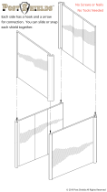
Step 11
Place all 4 cone sections on a flat surface with tabs from one facing slots of the next. See Figure 11A.
Curl up tab end of first cone section and insert tabs up into slots in the next cone section. A mallet may
be needed to seat slots over tabs completely.
See Figure 11B. Repeat this until all 4 cone sections are
connected and laying flat.
Installation InstructionsChapter 2
Step 12A
For WS55xK Fan fasten each of the joints in the single outer hole using (1) Short Bolt [K] and Nut [L], with the
nut on the side with the tabs. At the inner pair of holes of each joint attach (1) Cone Support Bracket to the
inner hole using (1) Short Bolt [K] and Nut [L] with the bolt head on the side with the tabs. For WS55xP Fan
fasten each of the joints in the single outer hole using (1) Short Bolt [D] and Nut [E], with the nut on the side
with the tabs. At the inner pair of holes of each joint attach (1) Cone Support Bracket to the inner hole using
(1) Short Bolt [D] and Nut [E] with the bolt head on the side with the tabs.
See Figure 12A.
Figure 11A
Figure 12A
Nut [L]/[E]
Figure 11B
Outer Hole
Short Bolt [K]/[D]
Short Bolt [K]/[D]
Inner holes
Nut [L]/[E]
Cone Support Bracket
2.4 Cone Installation

15© Munters Corporation, November 2019
QM1232r2
Installation InstructionsChapter 2
Step 12B
Stand cone sections on end and curl ends around to form cone with Cone Support Bracket on outside and tabs
on inside. Insert remaining tabs into slots so tabs are inside cone. For WS55xK Fan fasten final joint using
(1) Short Bolt [K] and Nut [L], with nut on inside of cone. At the inner pair of holes attach (1) Cone Support
Bracket to the inner hole using (1) Short Bolt [K] and Nut [L] with bolt head on inside of cone. For WS55xP
Fan fasten final joint using (1) Short Bolt [D] and Nut [E], with nut on inside of cone. At the inner pair of holes
attach (1) Cone Support Bracket to the inner hole using (1) Short Bolt [D] and Nut [E] with bolt head on inside
of cone.
See Figure 12B.
Short Bolt [K]/[D]
Cone Support Bracket
Nut [L]/[E]
Short Bolt [K]/[D]
Nut [L]/[E]
Figure 12B

© Munters Corporation, November 2019
16
QM1232r2
Installation InstructionsChapter 2
Figure 13A
Step 13A
Install cone onto fan by putting top of cone over top of fan outlet and allow remainder of cone to slide over outlet
making sure Cone Support Brackets remain on outside of fan. Cone Support Brackets should line up with holes in
housing.
See Figure 13A.
Cone Support Bracket
Step 13B
For WS55xK Fan fasten end of Cone Support Bracket with slot to fan housing using Short Bolt [K],
Flat Washer [M] and Nut [L]. For WS55xP Fan fasten end of Cone Support Bracket with slot to fan
housing using Short Bolt [D], Flat Washer [B] and Nut [E]. Repeat for each corner. See Figure 13B.
Figure 13B
Nut [L]/[E]
Flat Washer [M]/[B]
Short Bolt [K]/[D]

17© Munters Corporation, November 2019
QM1232r2
Installation InstructionsChapter 2
Step 13C
For WS55xK Fan secure the Cone and Cone Support Bracket to fan housing by inserting Short Bolt [K] into hole
from the inside out and secure with Nut [L]. For WS55xP Fan secure the Cone and Cone Support Bracket to
fan housing by inserting Short Bolt [D] into hole from the inside out and secure with Nut [E]. Repeat process for
all 4 Cone Support Brackets.
See Figure 13C.
Figure 13C
Short Bolt [K]/[D]
Nut [L]/[E]
Step 14
For WS55xK Fan insert guard into cone with the eyelets facing you. Install eyelets over bolts already installed
in cone and fasten with Nut [L]. Secure remaining eyelets using Short Bolt [K] and Nut [L]. For WS55xP Fan
insert guard into cone with the eyelets facing you. Install eyelets over bolts already installed in cone and fasten
with Nut [E]. Secure remaining eyelets using Short Bolt [D] and Nut [E]. See Figure 14.
Figure 14
Short Bolt [K]/[D]
Nut [L]/[E]
Previously installed - Bolt and Nut
Nut [L]/[E]

© Munters Corporation, November 2019
18
QM1232r2
Step 15
If the fan came with an outlet guard instead of a cone, slide the guard over fan orifice and secure to fan
using (8) Truss Head Bolts [N] and Nylock Nuts [P] with the head of the bolt on the inside of the orifice
and the nut on the outside. See Figure 15.
Figure 15
Truss Head Bolt [N]
Nylock Nut [P]
Installation InstructionsChapter 2
Step 16
The Drain Holes in bottom of Fan Housing can be plugged if preferred, using provided Hole Plugs [J].
See Figure 16.
Figure 16
Hole Plug [J]
Drain Holes in Bottom of Fan Housing

19© Munters Corporation, November 2019
QM1232r2
Installation InstructionsChapter 2
Step 17
Insert shutter into fan by sliding the bottom flange of shutter into bottom shutter clips and pressing shutter
inward,
See Figure 17A
. Fasten shutter in place by rotating the side and top shutter clips over the
shutter flanges,
See Figure 17B.
Installation is now complete, proceed to electrical wiring section.
Figure 17A
Figure 17B
Fixed Shutter Clip [N]
Shutter

© Munters Corporation, November 2019
20
QM1232r2
All wiring should be installed in accordance with National, State, and Local electrical codes. Fans used to
ventilate livestock buildings or other rooms where continuous air movement is essential should be connected to
individual electrical circuits, with a minimum of two circuits per room. For electrical connection requirements, refer
to diagram on motor nameplate and to information enclosed with the Munters environmental control to be used.
Single Phase Fans: motor overload protection should be provided for each fan. A Circuit Breaker Switch or slow
blow motor type fuses must be used, See Figure 18A. See form QM1400 for proper size.
Three Phase Fans: motor overload protection should be provided for each fan. A three-pole motor starter or slow
blow motor fuses must be used. See Figure 18B.
If a frequency drive (inverter) is used, confirm that motors are rated for inverter duty at the voltage used. The
installation of line reactors is recommended to reduce voltage spikes and harmonic distortion. Supplemental
motor overload protection is also recommended.
NOTE: A safety cut-off switch should be located adjacent to each fan.
Figure 18A
Single Phase - Motor Overload Protection with Disconnect
(SY2000 or Equivalent)
120 or 240 VAC
Power Supply for
Fan
L1 (H)
L2 (N)
G
T1 (H)
T2 (N)
G
120 or 240 VAC
Power Out
to Fan
L1 (H)
L2 (N)
T1 (H)
T2 (N)
KEY:
L1=Line 1
L2=Line 2
L3=Line 3
H=Hot
N=Neutral
G=Ground
NOTE: Information in parenthesis refers to 120 VAC control.
Three Phase
Power Supply for
Fan
L1
L2
G
T1
T2
G
Three Phase
Power Out
to Fan Motor
L1
L2
T1
T2
L3
T3
L3
T3
Figure 18B
Three Phase - Motor Overload Protection with Disconnect
Safety cut-off
switch
Motor Starter
Electrical Wiring
3.
Circuit Breaker Switch
/