Page is loading ...

L1000A AC Elevator Drive
Quick Start Guide
Type: CIMR-LU A
Models: 200 V Class: 1.5 to 110 kW (2 to 150 HP)
400 V Class: 1.5 to 132 kW (2 to 200 HP)
To properly use the product, read this manual thoroughly and retain for easy reference,
inspection, and maintenance. Ensure that the end user receives this manual.
TM7349 rev 02
© Magnetek Elevator 2012

2 Magnetek L1000A AC Drive for Elevator Applications Quick Start Guide
Copyright © 2012 MAGNETEK.
All rights reserved. No part of this publication may be reproduced, stored in a retrieval system, or transmitted,
in any form, or by any means, mechanical, electronic, photocopying, recording, or otherwise, without the prior
written permission of Magnetek. No patent liability is assumed with respect to the use of the information
contained herein. Moreover, because Magnetek is constantly striving to improve its high-quality products, the
information contained in this manual is subject to change without notice. Every precaution has been taken in
the preparation of this manual. Nevertheless, Magnetek assumes no responsibility for errors or omissions.
Neither is any liability assumed for damages resulting from the use of the information contained in this
publication.
TM7349_rev_01.book Page 2 Wednesday, December 5, 2012 10:47 AM

Magnetek L1000A AC Drive for Elevator Applications Quick Start Guide 3
◆ Quick Reference
Drive a Synchronous PM Motor
L1000A can operate synchronous PM motors. Flowchart C: Auto-Tuning for PM Motors on
page 59.
Perform Auto-Tuning
Automatic tuning sets motor parameters. Refer to Types of Auto-Tuning on page 61.
Maintenance Check Using Drive Monitors
Use drive monitors to check fans, capacitors, and other components may require maintenance. Refer to Performance Life Monitors Maintenance
Monitors on page 123.
Fault Display and Troubleshooting
Refer to Troubleshooting on page 110.
Standards Compliance
Refer to European Standards on page 188 and UL and CSA Standards on page 195.
CSA B44.1 /
ASME A17.5
YEA
_co
mmo
n
TM7349_rev_01.book Page 3 Wednesday, December 5, 2012 10:47 AM

4 Magnetek L1000A AC Drive for Elevator Applications Quick Start Guide
This Page Intentionally Blank
TM7349_rev_01.book Page 4 Wednesday, December 5, 2012 10:47 AM

Magnetek L1000A AC Drive for Elevator Applications Quick Start Guide 5
Table of Contents
Quick Reference . . . . . . . . . . . . . . . . . . . . . . . . . . . . . . . . . . . . . . . . . . . . . . . . . . . . . . .3
i. Preface & General Safety ................................................................................................. 7
Preface . . . . . . . . . . . . . . . . . . . . . . . . . . . . . . . . . . . . . . . . . . . . . . . . . . . . . . . . . . . . . .7
General Safety. . . . . . . . . . . . . . . . . . . . . . . . . . . . . . . . . . . . . . . . . . . . . . . . . . . . . . . . .7
1. Receiving ......................................................................................................................... 15
Model Number and Nameplate Check . . . . . . . . . . . . . . . . . . . . . . . . . . . . . . . . . . . . .15
2. Mechanical Installation ................................................................................................... 17
Mechanical Installation . . . . . . . . . . . . . . . . . . . . . . . . . . . . . . . . . . . . . . . . . . . . . . . . .17
3. Electrical Installation ...................................................................................................... 21
Standard Connection Diagram . . . . . . . . . . . . . . . . . . . . . . . . . . . . . . . . . . . . . . . . . . .21
Main Circuit Connection Diagram . . . . . . . . . . . . . . . . . . . . . . . . . . . . . . . . . . . . . . . . .24
Terminal Cover . . . . . . . . . . . . . . . . . . . . . . . . . . . . . . . . . . . . . . . . . . . . . . . . . . . . . . . 25
Digital Operator and Front Cover . . . . . . . . . . . . . . . . . . . . . . . . . . . . . . . . . . . . . . . . .27
Main Circuit Wiring . . . . . . . . . . . . . . . . . . . . . . . . . . . . . . . . . . . . . . . . . . . . . . . . . . . .29
Control I/O Configuration. . . . . . . . . . . . . . . . . . . . . . . . . . . . . . . . . . . . . . . . . . . . . . . . 44
Connect to a PC . . . . . . . . . . . . . . . . . . . . . . . . . . . . . . . . . . . . . . . . . . . . . . . . . . . . . .45
Wiring Checklist. . . . . . . . . . . . . . . . . . . . . . . . . . . . . . . . . . . . . . . . . . . . . . . . . . . . . . .46
4. Start-Up Programming & Operation ............................................................................. 47
Using the Digital Operator . . . . . . . . . . . . . . . . . . . . . . . . . . . . . . . . . . . . . . . . . . . . . . . 47
The Drive and Programming Modes . . . . . . . . . . . . . . . . . . . . . . . . . . . . . . . . . . . . . . .52
Start-Up Flowcharts. . . . . . . . . . . . . . . . . . . . . . . . . . . . . . . . . . . . . . . . . . . . . . . . . . . .54
Setup Procedure for Elevator Applications . . . . . . . . . . . . . . . . . . . . . . . . . . . . . . . . . .69
S: Elevator Parameters . . . . . . . . . . . . . . . . . . . . . . . . . . . . . . . . . . . . . . . . . . . . . . . . . 78
Setup Troubleshooting and Possible Solutions. . . . . . . . . . . . . . . . . . . . . . . . . . . . . .107
5. Troubleshooting............................................................................................................ 110
Fault Detection . . . . . . . . . . . . . . . . . . . . . . . . . . . . . . . . . . . . . . . . . . . . . . . . . . . . . . 110
Alarm Detection . . . . . . . . . . . . . . . . . . . . . . . . . . . . . . . . . . . . . . . . . . . . . . . . . . . . . .114
Operator Programming Errors . . . . . . . . . . . . . . . . . . . . . . . . . . . . . . . . . . . . . . . . . . .116
Auto-Tuning Fault Detection . . . . . . . . . . . . . . . . . . . . . . . . . . . . . . . . . . . . . . . . . . . .117
Copy Function Related Displays . . . . . . . . . . . . . . . . . . . . . . . . . . . . . . . . . . . . . . . . .118
6. Periodic Inspection & Maintenance ............................................................................ 120
Inspection . . . . . . . . . . . . . . . . . . . . . . . . . . . . . . . . . . . . . . . . . . . . . . . . . . . . . . . . . .120
Periodic Maintenance . . . . . . . . . . . . . . . . . . . . . . . . . . . . . . . . . . . . . . . . . . . . . . . . .122
Drive Replacement . . . . . . . . . . . . . . . . . . . . . . . . . . . . . . . . . . . . . . . . . . . . . . . . . . . 124
7. Option Card Installation ............................................................................................... 127
Prior to Installing the Option . . . . . . . . . . . . . . . . . . . . . . . . . . . . . . . . . . . . . . . . . . . .127
Installing the Option. . . . . . . . . . . . . . . . . . . . . . . . . . . . . . . . . . . . . . . . . . . . . . . . . . .128
Wire Gauges, Tightening Torque, and Crimp Terminals . . . . . . . . . . . . . . . . . . . . . . .135
Terminal Functions of PG-B3 and PG-X3 Option . . . . . . . . . . . . . . . . . . . . . . . . . . . .136
A. Specifications................................................................................................................ 137
Three-Phase 200 V Class Drives . . . . . . . . . . . . . . . . . . . . . . . . . . . . . . . . . . . . . . . .137
Three-Phase 400 V Class Drives . . . . . . . . . . . . . . . . . . . . . . . . . . . . . . . . . . . . . . . .138
TM7349_rev_01.book Page 5 Wednesday, December 5, 2012 10:47 AM

Table of Contents
6 Magnetek L1000A AC Drive for Elevator Applications Quick Start Guide
Drive Specifications . . . . . . . . . . . . . . . . . . . . . . . . . . . . . . . . . . . . . . . . . . . . . . . . . . .139
B. Parameter Table ............................................................................................................ 141
A: Initialization Parameters . . . . . . . . . . . . . . . . . . . . . . . . . . . . . . . . . . . . . . . . . . . . .141
b: Application . . . . . . . . . . . . . . . . . . . . . . . . . . . . . . . . . . . . . . . . . . . . . . . . . . . . . . . .142
C: Tuning . . . . . . . . . . . . . . . . . . . . . . . . . . . . . . . . . . . . . . . . . . . . . . . . . . . . . . . . . . .144
d: Speed References. . . . . . . . . . . . . . . . . . . . . . . . . . . . . . . . . . . . . . . . . . . . . . . . . .148
E: Motor Parameters . . . . . . . . . . . . . . . . . . . . . . . . . . . . . . . . . . . . . . . . . . . . . . . . . .150
F: Option Settings . . . . . . . . . . . . . . . . . . . . . . . . . . . . . . . . . . . . . . . . . . . . . . . . . . . .154
H: Multi-Function Terminals. . . . . . . . . . . . . . . . . . . . . . . . . . . . . . . . . . . . . . . . . . . . .158
L: Protection Functions . . . . . . . . . . . . . . . . . . . . . . . . . . . . . . . . . . . . . . . . . . . . . . . .164
n: Advanced Performance Set-Up. . . . . . . . . . . . . . . . . . . . . . . . . . . . . . . . . . . . . . . .168
o: Operator Related Parameters . . . . . . . . . . . . . . . . . . . . . . . . . . . . . . . . . . . . . . . . .170
S: Elevator Parameters . . . . . . . . . . . . . . . . . . . . . . . . . . . . . . . . . . . . . . . . . . . . . . . .173
T: Motor Tuning . . . . . . . . . . . . . . . . . . . . . . . . . . . . . . . . . . . . . . . . . . . . . . . . . . . . . .177
U: Monitors . . . . . . . . . . . . . . . . . . . . . . . . . . . . . . . . . . . . . . . . . . . . . . . . . . . . . . . . .179
Defaults and Setting Ranges by Display Unit Selection (o1-03) . . . . . . . . . . . . . . . . .187
C. Standards Compliance ................................................................................................. 188
European Standards . . . . . . . . . . . . . . . . . . . . . . . . . . . . . . . . . . . . . . . . . . . . . . . . . .188
UL and CSA Standards . . . . . . . . . . . . . . . . . . . . . . . . . . . . . . . . . . . . . . . . . . . . . . . .195
Safe Disable Input Function . . . . . . . . . . . . . . . . . . . . . . . . . . . . . . . . . . . . . . . . . . . .204
EN81-1 Conform Circuit with one Motor Contactor . . . . . . . . . . . . . . . . . . . . . . . . . . .207
Revision History..............................................................................................................208
TM7349_rev_01.book Page 6 Wednesday, December 5, 2012 10:47 AM

i Preface & General Safety
MAGNETEK L1000A AC Drive for Elevator Applications Quick Start Guide 7
i Preface & General Safety
◆ Preface
Magnetek manufactures products used as components in a wide variety of industrial systems and equipment. The
selection and application of Magnetek products remain the responsibility of the equipment manufacturer or end user.
Magnetek accepts no responsibility for the way its products are incorporated into the final system design. Under no
circumstances should any Magnetek product be incorporated into any product or design as the exclusive or sole safety
control. Without exception, all controls should be designed to detect faults dynamically and fail safely under all
circumstances. All systems or equipment designed to incorporate a product manufactured by Magnetek must be supplied
to the end user with appropriate warnings and instructions as to the safe use and operation of that part. Any warnings
provided by Magnetek must be promptly provided to the end user. Magnetek offers an express warranty only as to the
quality of its products in conforming to standards and specifications published in the Magnetek manual. NO OTHER
WARRANTY, EXPRESS OR IMPLIED, IS OFFERED. Magnetek assumes no liability for any personal injury, property
damage, losses, or claims arising from misapplication of its products.
This manual is designed to ensure correct and suitable application of L1000A-Series Drives. Read this manual before
attempting to install, operate, maintain, or inspect a drive and keep it in a safe, convenient location for future reference.
Be sure you understand all precautions and safety information before attempting application.
■
Applicable Documentation
The following manuals are available for L1000A series drives:
◆ General Safety
■
Supplemental Safety Information
L1000A Series AC Drive Quick Start Guide (this book)
Read this manual first. This guide is packaged together with the product. It contains basic
information required to install and wire the drive, in addition to an overview of fault diagnostics,
maintenance, and parameter settings. Use the information in this book to prepare the drive for a trial
run with the application and for basic operation.
L1000A Series AC Drive Technical Manual
This manual provides detailed information on parameter settings, drive functions, and MEMOBUS/
Modbus specifications. Use this manual to expand drive functionality and to take advantage of
higher performance features.
General Precautions
• The diagrams in this manual may be indicated without covers or safety shields to show details. Replace the covers or shields before operating the
drive and run the drive according to the instructions described in this manual.
• Any illustrations, photographs, or examples used in this manual are provided as examples only and may not apply to all products to which this
manual is applicable.
• The products and specifications described in this manual or the content and presentation of the manual may be changed without notice to
improve the product and/or the manual.
• When ordering a new copy of the manual due to damage or loss, contact your Magnetek representative or the nearest Magnetek sales office and
provide the manual number shown on the front cover.
• If nameplate becomes worn or damaged, order a replacement from your Magnetek representative or the nearest Magnetek sales office.
W ARNING
Read and understand this manual before installing, operating or servicing this drive. The drive must be installed
according to this manual and local codes.
The following conventions are used to indicate safety messages in this manual. Failure to heed these messages could
result in serious or fatal injury or damage to the products or to related equipment and systems.
CIMR-AA2A0021FAA
200V 3Phase 5.5kW/3.7kW
S/N:
5
400V
5
AVERTISSMENT
NPJT31470-1
Lire le manuel avant l'installation.
Attendre 5 minutes après la coupure
de l'alimentation, pour permettre
la décharge des condensateurs.
Pour répondre aux exigences , s
assurer que le neutre soit relié
à la terre, pour la série 400V.
Après avoir déconnécte la protection
entre le driver et le moteur, veuillez
patienter 5 minutes avain d’effectuer
une opération de montage ou de
câblage du variateur.
Risque de décharge électrique.
Surfaces Chaudes
Dessus et cotés du boitier Peuvent
devenir chaud. Ne Pas toucher.
WARNIN G
Read manual before installing.
Wait 5 minutes for capacitor
discharge after disconnecting
power supply.
To conform to requirements,
make sure to ground the supply
neutral for 400V class.
After opening the manual switch
between the drive and motor,
please wait 5 minutes before
inspecting, performing
maintenance or wiring the drive.
Risk of electric shock.
Hot surfaces
Top and Side surfaces may
become hot. Do not touch.
LO
RE
F2F1
ESC
RUN STOP
ENTERRESET
ALM
DIGITAL OPERATOR JVOP-180
YEA_
common
TM7349_rev_01.book Page 7 Wednesday, December 5, 2012 10:47 AM

i Preface & General Safety
8 MAGNETEK L1000A AC Drive for Elevator Applications Quick Start Guide
WARNING! may also be indicated by a bold key word embedded in the text followed by an italicized safety message.
CAUTION! may also be indicated by a bold key word embedded in the text followed by an italicized safety message.
NOTICE: may also be indicated by a bold key word embedded in the text followed by an italicized safety message.
■
Safety Messages
DANGER
Indicates a hazardous situation, which, if not avoided, will result in death or serious injury.
W ARNING
Indicates a hazardous situation, which, if not avoided, could result in death or serious injury.
CAUTION
Indicates a hazardous situation, which, if not avoided, could result in minor or moderate injury.
NOTICE
Indicates a property damage message.
DANGER
Heed the safety messages in this manual.
Failure to comply will result in death or serious injury.
The operating company is responsible for any injuries or equipment damage resulting from failure to heed the warnings
in this manual.
Electrical Shock Hazard
Do not connect or disconnect wiring or service the drive while the power is on.
Failure to comply will result in death or serious injury.
Before servicing, disconnect all power to the equipment. The internal capacitor remains charged even after the power
supply is turned off. After shutting off the power, wait for at least the amount of time specified on the drive before
touching any components.
W ARNING
Sudden Movement Hazard
The drive system or elevator may start unexpectedly upon application of power, resulting in death or serious
injury.
• Clear all personnel from the drive, motor, and machine area before applying power.
• Secure covers, couplings, shaft keys, and machine loads before applying power to the drive.
Ensure there are no short circuits between the main circuit terminals (R/L1, S/L2, and T/L3) or between the
ground and main circuit terminals before restarting the drive.
Failure to comply may result in serious injury or death and will cause damage to equipment.
TM7349_rev_01.book Page 8 Wednesday, December 5, 2012 10:47 AM

i Preface & General Safety
MAGNETEK L1000A AC Drive for Elevator Applications Quick Start Guide 9
System may start unexpectedly upon application of power when the Auto-restart function is enabled resulting in
death or serious injury.
Use care when enabling Auto-restart as this function may cause unintended start of the elevator.
Use parameter S1-12 to enable/disable automatic switching of the Motor Contactor Control output signal
during Auto-Tuning.
When using setting S1-12 = 1, ensure that the multi-function output terminals are properly wired and in the correct
state before setting parameter S1-12.
Failure to comply could result in damage to the drive, serious injury or death.
Electrical Shock Hazard
Do not attempt to modify or alter the drive in any way not explained in this manual.
Magnetek is not responsible for damage caused by modification of the product made by the user. Failure to comply
could result in death or serious injury from operation of damaged equipment.
Do not operate equipment with covers removed.
Failure to comply could result in death or serious injury.
The diagrams in this section may show drives without covers or safety shields to show details. Be sure to reinstall
covers or shields before operating the drives and run the drives according to the instructions described in this manual.
When a drive is running a PM motor, voltage continues to be generated at the motor terminals after the drive is
shut off while the motor coasts to stop. Take the precautions described below to prevent shock and injury:
• In applications where the machine can still rotate even though the drive has fully stopped a load, install a switch to
the drive output side to disconnect the motor and the drive.
• Do not allow an external force to rotate the motor beyond the maximum allowable speed or to rotate the motor when
the drive has been shut off.
• Wait for at least the time specified on the warning label after opening the load switch on the output side before
inspecting the drive or performing any maintenance.
• Do not open and close the load switch while the motor is running, as this can damage the drive.
If the motor is coasting, make sure the power to the drive is turned on and the drive output has completely stopped
before closing the load switch.
Do not connect or disconnect wiring to the drive or motor while the power is on.
Failure to comply will result in death or serious injury. Before servicing, disconnect all power to the equipment. The
internal capacitor remains charged even after the power supply is turned off. The charge indicator LED will extinguish
when the DC bus voltage is below 50 Vdc. To prevent electric shock, wait at least five minutes after all indicators are
OFF and measure the DC bus voltage level to confirm safe level.
Do not operate equipment with covers removed.
Failure to comply could result in death or serious injury.
The diagrams in this section may show drives without covers or safety shields to show details. Be sure to reinstall
covers or shields before operating the drives and run the drives according to the instructions described in this manual.
Do not perform work on the drive while wearing loose clothing, jewelry or without eye protection.
Failure to comply could result in death or serious injury.
Remove all metal objects such as watches and rings, secure loose clothing, and wear eye protection before beginning
work on the drive.
W ARNING
TM7349_rev_01.book Page 9 Wednesday, December 5, 2012 10:47 AM

i Preface & General Safety
10 MAGNETEK L1000A AC Drive for Elevator Applications Quick Start Guide
Do not change wiring, remove covers, connectors or options cards, or attempt to service the drive with power
applied to the drive.
Failure to comply could result in death or serious injury. Disconnect all power to the drive and check for unsafe
voltages before servicing.
Do not allow unqualified personnel to use the equipment.
Failure to comply could result in death or serious injury.
Maintenance, inspection, and replacement of parts must be performed only by authorized personnel familiar with
installation, adjustment and maintenance of AC drives.
Fire Hazard
Drive Short-Circuit Current Rating
Install adequate branch circuit protection according to applicable local codes and this Installation Manual.
Failure to comply could result in fire and damage to the drive or injury to personnel.
The device is suitable for use on a circuit capable of delivering not more than 100,000 RMS symmetrical amperes, 240
Vac maximum (200 V class) and 480 Vac maximum (400 V class), and 600 Vac maximum (600 V class) when
protected by branch circuit protection devices specified in this manual.
Applications using a braking option should wire a thermal relay so that the output contactor opens when the
thermal relay trips.
Inadequate braking circuit protection could result in death or serious injury by fire from overheating resistors.
Do not use improper combustible materials.
Failure to comply could result in death or serious injury by fire.
Attach the drive to metal or other noncombustible material.
NOTICE
Equipment Hazard
Do not modify the drive circuitry.
Failure to comply could result in damage to the drive and will void warranty.
Magnetek is not responsible for any modification of the product made by the user. This product must not be modified.
Failure to comply could result in damage to the drive or braking circuit.
Observe proper electrostatic discharge procedures (ESD) when handling the drive, circuit boards, and option
cards.
Failure to comply may result in ESD damage to the drive circuitry.
Do not operate damaged equipment.
Failure to comply could result in further damage to the equipment.
Do not connect or operate any equipment with visible damage or missing parts.
Do not lift the drive up while the cover is removed.
This can damage the terminal board and other components.
Do not expose the drive to halogen group disinfectants.
Failure to comply may cause damage to the electrical components in the drive.
Do not pack the drive in wooden materials that have been fumigated or sterilized.
Do not sterilize the entire package after the product is packed.
W ARNING
TM7349_rev_01.book Page 10 Wednesday, December 5, 2012 10:47 AM

i Preface & General Safety
MAGNETEK L1000A AC Drive for Elevator Applications Quick Start Guide 11
■
General Application Precautions
Motor Selection
Drive Capacity
The output current should not exceed 150% of the drive rated current. Select a drive that can output enough current when
accelerating a load at 100%.
For specialized motors, make sure that the motor rated current is less than the rated output current for the drive.
Starting Torque
The startup and acceleration characteristics of the motor are restricted to the drive's overload current rating (150% rated
current for 60 s).
The overload rating for the drive determines the starting and accelerating characteristics of the motor. Expect lower
torque than when running from line power. To get more starting torque, use a larger drive or increase both the motor and
drive capacity.
Stopping
Fast Stop
When the drive faults out, a protective circuit is activated and drive output is shut off. This, however, does not stop the
motor immediately. A mechanical brake may be required to stop the motor if Fast Stop deceleration is insufficient.
Mechanical Brake
A mechanical brake is required to prevent the elevator from free falling during a drive fault condition.
Repetitive Starting/Stopping
Elevators and other applications with frequent starts and stops often approach 150% of their rated current values. Heat
stress generated from repetitive high current will shorten the life span of the IGBTs.
Magnetek recommends lowering the carrier frequency, particularly when audible noise is not a concern. It is beneficial to
reduce the load, increase the acceleration and deceleration times, or switch to a larger drive to help keep peak current
levels under 150%. Be sure to check the peak current levels when starting and stopping repeatedly during the initial test
run, and make adjustments accordingly.
Installation
Enclosure Panels
Keep the drive in a clean environment by installing the drive in an enclosure panel or selecting an installation area free of
airborne dust, lint, and oil mist. Be sure to leave the required space between drives to provide for cooling, and take proper
measures so the ambient temperature remains within allowable limits and keep flammable materials away from the drive.
Magnetek offers protective designs for drives that must be used in areas subjected to oil mist and excessive vibration.
Contact Magnetek or your Magnetek representative for details.
Installation Direction
NOTICE: Install the drive upright as specified in the manual. Refer to Mechanical Installation on page 17 for more information on
installation. Failure to comply may damage the drive due to improper cooling.
Settings
DC Injection Braking
NOTICE: Excessive current during DC Injection Braking and excessive duration of DC Injection Braking can cause motor overheating.
Adjust DC Injection parameters to prevent motor overheating.
Acceleration/Deceleration Ramp
Acceleration and deceleration times are affected by the amount of torque generated by the motor, the load torque, and the
inertia moment. Set a longer accel/decel time when Stall Prevention is enabled. The accel/decel times are lengthened for
as long as the Stall Prevention function is in operation. Install one of the available braking options or increase the capacity
of the drive for faster acceleration and deceleration.
TM7349_rev_01.book Page 11 Wednesday, December 5, 2012 10:47 AM

i Preface & General Safety
12 MAGNETEK L1000A AC Drive for Elevator Applications Quick Start Guide
General Handling
Selecting a Molded Case Circuit Breaker or Ground Fault Circuit Interrupter (GFCI)
Select an appropriate GFCI. This drive can cause a residual current with a DC component in the protective earthing
conductor. Where a residual current operated protective or monitoring device is used for protection in case of direct or
indirect contact, always use an GFCI of type B according to IEC 60755.
Select a MCCB (Molded Case Circuit Breaker) with a rated current that is 1.5 to 2 times higher than the rated current of
the drive in order to avoid nuisance trips caused by harmonics in the drive input current.
WARNING! Sudden Movement Hazard. Install a properly controlled contactor on the input-side of the drive for applications where
power should be removed from the drive during a fault condition. Improper equipment sequencing could result in death or serious
injury.
WARNING! Fire Hazard. Shut off the drive with a magnetic contactor (MC) when a fault occurs in any external equipment such as
braking resistors. Failure to comply may cause resistor overheating, fire, and injury to personnel.
NOTICE: To get the full performance life out of the electrolytic capacitors and circuit relays, refrain from switching the drive power
supply off and on more than once every 30 minutes. Frequent use can damage the drive. Use the drive to stop and start the motor.
Inspection and Maintenance
WARNING! Electrical Shock Hazard. Capacitors in the drive do not immediately discharge after shutting off the power. Wait for at least
the amount of time specified on the drive before touching any components after shutting off the power. Failure to comply may cause
injury to personnel from electrical shock.
CAUTION! Burn Hazard. Because the heatsink can get very hot during operation, take proper precautions to prevent burns. When
replacing the cooling fan, shut off the power and wait at least 15 minutes to be sure that the heatsink has cooled down. Failure to
comply may cause burn injury to personnel.
WARNING! Electrical Shock Hazard. When a drive is running a PM motor, voltage continues to be generated at the motor terminals
after the drive is shut off while the motor coasts to stop. Take the precautions described below to prevent shock and injury:
• In applications where the machine can still rotate after the drive has fully stopped a load, install a load disconnect
switch on the drive output side to disconnect the motor and the drive.
• Do not allow an external force to rotate the motor beyond the maximum allowable speed or to rotate the motor when the
drive is powered off.
• Wait for at least the time specified on the warning label after opening the load switch on the output side before
inspecting the drive or performing any maintenance.
• Do not open and close the load switch while the motor is running.
• If the motor is coasting, make sure the power to the drive is turned on and the drive output has completely stopped
before closing the load switch to reconnect the drive to the motor.
Wiring
Magnetek recommends using ring terminals on all drive models for UL/cUL compliance. Use only the tools
recommended by the terminal manufacturer for crimping.
Transporting the Drive
NOTICE: Never steam clean the drive. During transport, keep the drive from coming into contact with salts, fluorine, bromine, phthalate
ester, and other such harmful chemicals. Failure to comply may damage the drive.
TM7349_rev_01.book Page 12 Wednesday, December 5, 2012 10:47 AM

i Preface & General Safety
MAGNETEK L1000A AC Drive for Elevator Applications Quick Start Guide 13
■
Motor Application Precautions
Standard Induction Motors
Insulation Tolerance
NOTICE: Consider motor voltage tolerance levels and motor insulation in applications with an input voltage of over 440 V or particularly
long wiring distances.
NOTICE: Ensure that the motor is suitable for inverter duty and/or the motor service factor is adequate to accommodate the additional
heating with the intended operating conditions. A motor connected to a PWM drive may operate at a higher temperature than a utility-
fed motor and the operating speed range may reduce motor cooling capacity.
High-Speed Operation
NOTICE: Mechanical damage may occur with the motor bearings and dynamic balance of the machine when operating a motor
beyond its rated speed. Operate the motor within specifications to prevent motor damage.
Low-Speed Range
The cooling fan of a standard motor should sufficiently cool the motor at the rated speed. As the self-cooling capability of
such a motor reduces with the speed, applying full torque at low speed will possibly damage the motor. Reduce the load
torque as the motor slows to prevent motor damage from overheat. Use a motor designed specifically for operation with a
drive when 100% continuous torque is needed at low speeds.
Torque Characteristics
Torque characteristics differ compared to operating the motor directly from line power. The user should have a full
understanding of the load torque characteristics for the application.
Vibration and Shock
The drive allows selection of high carrier PWM control and low carrier PWM control. Selecting high carrier PWM can
help reduce motor oscillation.
If resonance occurs, install shock-absorbing rubber mounts around the base of the motor and utilize the Jump frequency
selection to prevent continuous operation in the resonant frequency ranges.
Audible Noise
Noise created during run varies by the carrier frequency setting. When using a high carrier frequency, audible noise from
the motor is comparable to the motor noise generated when running from line power. Operating above the rated r/min,
however, can create unpleasant motor noise.
Precautions for PM Motors
NOTICE: Damage to Equipment. Improper sequencing of output motor circuits could result in damage to the drive. Do not connect
electromagnetic switches or magnetic contactors to the output motor circuits without proper sequencing. Do not open the main circuit
between the drive and the motor while the PM motor is rotating.
• Contact Magnetek or your Magnetek representative if you plan to use any PM motor not endorsed by Magnetek.
• When using a holding brake, release the brake prior to starting the motor. Failure to set the proper timing can result in
speed loss.
WARNING! Sudden Movement Hazard. Use the Initial Pole Search Status Signal (H2-= 61) to interlock the brake to ensure the
brake is not released before the Initial Magnetic Pole Search is completed. Failure to comply may cause inadvertent elevator
movement resulting in serious injury.
This safety message is applicable under these conditions:
• When applying a PM motor, with an external brake sequence, and the PG-F3 option is not being used.
WARNING! Electrical Shock Hazard. The motor must be at a complete stop before performing any maintenance, inspection, or wiring.
• With a PM motor, drive output must be fully interrupted when the power is shut off and the motor is still rotating.
Failure to comply can result in personal injury from electrical shock.
TM7349_rev_01.book Page 13 Wednesday, December 5, 2012 10:47 AM

i Preface & General Safety
14 MAGNETEK L1000A AC Drive for Elevator Applications Quick Start Guide
■
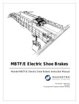
Drive Label Warnings
Always heed the warning information listed in Figure 1 in the position shown in Figure 2.
Figure 1
Figure 1 Warning Information
Figure 2
Figure 2 Warning Information Position
■
Warranty Information
Restrictions
The drive is not designed or manufactured for use in devices or systems that may directly affect or threaten human lives or
health.
Customers who intend to use the product described in this manual for devices or systems relating to transportation, health
care, space aviation, atomic power, electric power, or in underwater applications must first contact their Magnetek
representatives or the nearest Magnetek sales office.
WARNING! Injury to Personnel. This product has been manufactured under strict quality-control guidelines. However, if this product is
to be installed in any location where failure of this product could involve or result in a life-and-death situation or loss of human life or in
a facility where failure may cause a serious accident or physical injury, safety devices must be installed to minimize the likelihood of any
accident.
WARNING
Read manual before installing.
Wait 5 minutes for capacitor
discharge after disconnecting
power supply.
To conform to requirements,
make sure to ground the supply
neutral for 400V class.
After opening the manual switch
between the drive and motor,
please wait 5 minutes before
inspecting, performing
maintenance or wiring the drive.
Risk of electric shock.
Hot surfaces
Top and Side surfaces may
become hot. Do not touch.
CIMR
200V 3Phase 5.5kW/3.7kW
S/N:
5
400V
5
AVERTISSMENT
NPJT31470-1
Lire le manuel avant l'installation.
Attendre 5 minutes après la coupure
de l'alimentation, pour permettre
la décharge des condensateurs.
Pour répondre aux exigences , s
assurer que le neutre soit relié
à la terre, pour la série 400V.
Après avoir déconnécte la protection
entre le driver et le moteur, veuillez
patienter 5 minutes avain d’effectuer
une opération de montage ou de
câblage du variateur.
Risque de décharge électrique.
Surfaces Chaudes
Dessus et cotés du boitier Peuvent
devenir chaud. Ne Pas toucher.
WARN ING
Read manual before installing.
Wait 5 minutes for capacitor
discharge after disconnecting
power supply.
To conform to requirements,
make sure to ground the supply
neutral for 400V class.
After opening the manual switch
between the drive and motor,
please wait 5 minutes before
inspecting, performing
maintenance or wiring the drive.
Risk of electric shock.
Hot surfaces
Top and Side surfaces may
become hot. Do not touch.
LO
RE
F2F1
ESC
RUN STOP
ENTERRESET
ALM
DIGITAL OPERATOR JVOP-180
Warning Label
YEA_comm
on
TM7349_rev_01.book Page 14 Wednesday, December 5, 2012 10:47 AM

1 Receiving
MAGNETEK L1000A AC Drive for Elevator Applications Quick Start Guide 15
Receiving
1
1 Receiving
◆ Model Number and Nameplate Check
Please perform the following tasks after receiving the drive:
• Inspect the drive for damage.
If the drive appears damaged upon receipt, contact the shipper immediately.
• Verify receipt of the correct model by checking the information on the nameplate.
• If you have received the wrong model or the drive does not function properly, contact your supplier.
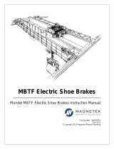
■
Nameplate
Figure 3
Figure 3 Nameplate Information
Description Drive
Controller Power Supply Cable
for Rescue Operation
Quick Start Guide
Quantity 111
YEA_co
mmon
Quick Start Guide
PRG : 1010
IND.CONT.EQ.
7J48 B
CIMR-LU2A0018DAA
REV: A
YASKAWA ELECTRIC CORPORATION
MADE IN JAPAN
:
: CIMR-LU2A0018DAA
: AC3PH 200-240V 50/60Hz 18.9A
: AC3PH 0-240V 0-120Hz 17.5A
: 3.5 kg
:
:
: E131457 IP00
PASS
MODEL
C / C
INPUT
OUTPUT
MASS
O / N
S / N
FILE NO
AC drive model
Input specifications
Output specifications
Lot number
Serial number
Software version
Enclosure type
YEA_common
TM7349_rev_01.book Page 15 Wednesday, December 5, 2012 10:47 AM

1 Receiving
16 MAGNETEK L1000A AC Drive for Elevator Applications Quick Start Guide
■
Model Number
<1> Drives with these specifications do not guarantee complete protection for the environmental conditions
indicated.
Table 1 Model Number and Specifications
Figure 4
Figure 5
Figure 6
Three-Phase 200 V Three-Phase 400 V
No.
Max. Motor
Capacity kW (HP)
Rated Output
Current A
No.
Max. Motor
Capacity kW (HP)
Rated Output
Current A
0008 1.5 (2) 8 0005 1.5 (2) 4.8
0011 2.2 (3) 11 0006 2.2 (3) 5.5
0014 3.0 (4) 14 0007 3.0 (4) 7.2
0018 3.7 (5) 17.5 0009 3.7 (5) 9.2
0025 5.5 (7-1/2) 25 0015 5.5 (7-1/2) 14.8
0033 7.5 (10) 33 0018 7.5 (10) 18
0047 11 (15) 47 0024 11 (15) 24
0060 15 (20) 60 0031 15 (20) 31
0075 18.5 (25) 75 0039 18.5 (25) 39
0085 22 (30) 85 0045 22 (30) 45
0115 30 (40) 115 0060 30 (40) 60
0145 37 (50) 145 0075 37 (50) 75
0180 45 (60) 180 0091 45 (60) 91
0215 55 (75) 215 0112 55 (75) 112
0283 75 (100) 283 0150 75 (100) 150
0346 90 (125) 346 0180 90 (125) 180
0415 110 (150) 415 0216 110 (150) 216
– – – 0260 132 (200) 260
CIMR
-
L U 2 A 0018 D A A
Drive
L1000A
Series
No.
Enclosure Type
Design
Revision
Order
No.
Customized
Specifications
A Standard model
No.
Region
Code
IP00
D
IP00 with top
protective cover
A
U U.S.A.
No. Voltage Class
No.
Environmental
Specification
A Standard
3-phase, 380-480 Vac
3-phase, 200-240 Vac 2
4
<1>
YEA_common
Refer to Table 1
TM7349_rev_01.book Page 16 Wednesday, December 5, 2012 10:47 AM

2 Mechanical Installation
MAGNETEK L1000A AC Drive for Elevator Applications Quick Start Guide 17
Mechanical
Installation
2
2 Mechanical Installation
◆ Mechanical Installation
This section outlines specifications, procedures, and the environment for proper mechanical installation of the drive.
CAUTION! Crush Hazard. Carrying the drive by the front cover may cause the main body of the drive to fall, resulting in minor or
moderate injury. Always hold the case when carrying the drive.
■
Installation Environment
Install the drive in an environment matching the specifications below to help prolong the optimum performance life of the
drive.
Table 2 Installation Environment
NOTICE: Avoid placing drive peripheral devices, transformers, or other electronics near the drive as the noise created can lead to
erroneous operation. If such devices must be used in close proximity to the drive, take proper steps to shield the drive from noise.
NOTICE: Prevent foreign matter such as metal shavings and wire clippings from falling into the drive during installation. Failure to
comply could result in damage to the drive. Place a temporary cover over the top of the drive during installation. Remove the temporary
cover before startup, as the cover will reduce ventilation and cause the drive to overheat.
Environment Conditions
Installation Area Indoors
Ambient Temperature
IP00 enclosure with top protective cover: -10 to +40°C
IP00 enclosure: -10 to +50°C
Drive reliability improves in environments without wide temperature fluctuations.
When using the drive in an enclosure panel, install a cooling fan or air conditioner in the area to ensure that the air
temperature inside the enclosure does not exceed the specified levels.
Do not allow ice to develop on the drive.
Humidity 95% RH or less and free of condensation
Storage Temperature -20 to 60°C
Surrounding Area
Install the drive in an area free from:
• oil mist and dust
• metal shavings, oil, water or other foreign materials
• radioactive materials
• combustible materials (e.g., wood)
• harmful gases and liquids
• excessive vibration
• chlorides
• direct sunlight
Altitude 1000 m or lower, up to 3000 m with derating (Refer to Altitude Derating on page 140)
Vibration
10 to 20 Hz at 9.8 m/s
2
20 to 55 Hz at 5.9 m/s
2
(2A0008 to 2A0180, 4A0005 to 4A0150) or 2.0 m/s
2
(2A0215 to 2A0415, 4A0180 to
4A0260)
Orientation Install the drive vertically to maintain maximum cooling effects.
TM7349_rev_01.book Page 17 Wednesday, December 5, 2012 10:47 AM

2 Mechanical Installation
18 MAGNETEK L1000A AC Drive for Elevator Applications Quick Start Guide
■
Installation Orientation and Spacing
WARNING! Fire Hazard. Provide sufficient cooling when installing the drive inside an enclosed panel or cabinet. Failure to comply
could result in overheating and fire. When drives are placed inside the same enclosure panel, install proper cooling to ensure air
entering the enclosure does not exceed 40
°
C.
Installation Orientation
Install the drive upright as illustrated in Figure 4 to maintain proper cooling. Refer to Mechanical Installation on
page 17 for details on installing the drive.
Figure 7
Figure 4 Correct Installation Orientation
Installation Spacing
Figure 5 shows the installation distance required to maintain sufficient space for airflow and wiring.
Figure 8
Figure 5 Correct Installation Spacing
A – 50 mm (1.97 in.) minimum C – 120 mm (4.72 in.) minimum
B – 30 mm (1.18 in.) minimum D – Airflow direction
OK Not OK Not OK
A
A
BB
Side Clearance Top/Bottom Clearance
C
C
D
D
YEA_common
TM7349_rev_01.book Page 18 Wednesday, December 5, 2012 10:47 AM

2 Mechanical Installation
MAGNETEK L1000A AC Drive for Elevator Applications Quick Start Guide 19
Mechanical
Installation
2
■
Exterior and Mounting Dimensions
IP00 Enclosure Drive with Top Protective Cover
Table 3 Dimensions: 200 V Class
Drive Model
CIMR-LU2A
Figure
Dimensions (in)
Weight
(lbs)
W H D W1 H1 H2 D1 t1 t2 d
0008
1
5.5 10.2 5.8 4.8 9.8 0.2 1.5 0.2 – M5 7.1
0011 5.5 10.2 5.8 4.8 9.8 0.2 1.5 0.2 – M5 7.1
0014 5.5 10.2 6.5 4.8 9.8 0.2 2.2 0.2 – M5 7.7
0018 5.5 10.2 6.5 4.8 9.8 0.2 2.2 0.2 – M5 7.7
0025 5.5 10.2 6.6 4.8 9.8 0.2 2.2 0.2 – M5 8.8
0033 5.5 10.2 6.6 4.8 9.8 0.2 2.2 0.2 – M5 8.8
0047 7.1 11.8 7.4 6.3 11.2 0.3 3.0 0.2 – M5 12.3
0060 8.713.87.8 7.613.20.3 3.1 0.2 – M619.2
0075 8.713.87.8 7.613.20.3 3.1 0.2 – M621.4
0085
2
9.8 15.7 10.2 7.7 15.2 0.3 3.9 0.1 0.1 M6 46.3
0115 10.8 17.7 10.2 8.7 17.1 0.3 3.9 0.1 0.1 M6 55.1
0145 12.8 21.7 11.1 10.2 21.1 0.3 4.3 0.1 0.1 M6 81.6
0180 12.8 21.7 11.1 10.2 21.1 0.3 4.3 0.1 0.1 M6 83.8
W1
0.06
H
H1
H2
W
D
D1
t1
Figure 1
4-d
Figure 2
W1
4-d
H1
H
H2
Max 0.31Max 0.31
W
t2
t1
D1
D
YEA_common
TM7349_rev_01.book Page 19 Wednesday, December 5, 2012 10:47 AM

2 Mechanical Installation
20 MAGNETEK L1000A AC Drive for Elevator Applications Quick Start Guide
Table 4 Dimensions: 400 V Class
IP00 Enclosure Drive
Table 5 Dimensions: 200 V Class
Table 6 Dimensions: 400 V Class
Drive Model
CIMR-LU4A
Figure
Dimensions (in)
Weight
(lbs)
W H D W1 H1 H2 D1 t1 t2 d
0005
1
5.5 10.2 5.8 4.8 9.8 0.2 1.5 0.2 – M5 7.1
0006 5.5 10.2 6.5 4.8 9.8 0.2 2.2 0.2 – M5 7.5
0007 5.5 10.2 6.5 4.8 9.8 0.2 2.2 0.2 – M5 7.7
0009 5.5 10.2 6.5 4.8 9.8 0.2 2.2 0.2 – M5 7.7
0015 5.5 10.2 6.6 4.8 9.8 0.2 2.2 0.2 – M5 8.6
0018 5.5 10.2 6.6 4.8 9.8 0.2 2.2 0.2 – M5 8.9
0024 7.1 11.8 6.6 6.3 11.2 0.3 2.2 0.2 – M5 11.9
0031 7.1 11.8 7.4 6.3 11.2 0.3 3.0 0.2 – M5 11.9
0039 8.7 13.8 7.8 7.6 13.2 0.3 3.1 0.2 – M6 18.3
0045
2
9.8 15.7 10.2 7.7 15.2 0.3 3.9 0.1 0.1 M6 46.3
0060 10.8 17.7 10.2 8.7 17.1 0.3 3.9 0.1 0.1 M6 55.1
0075 12.8 510 10.2 10.2 19.5 0.3 4.1 0.1 0.1 M6 79.4
0091 12.8 510 10.2 10.2 19.5 0.3 4.1 0.1 0.1 M6 79.4
0112 12.8 21.7 11.1 10.2 21.1 0.3 4.3 0.1 0.1 M6 90.4
0150 12.8 21.7 11.1 10.2 21.1 0.3 4.3 0.1 0.1 M6 92.6
Drive Model
CIMR-LU2A
Figure
Dimensions (in)
Weight
(lbs)
W H D W1 H1 H2 D1 t1 t2 d
0215
1
17.7 27.8 13.0 12.8 26.8 0.5 5.1 0.1 0.1 M10 167.6
0283 17.7 27.8 13.0 12.8 26.8 0.5 5.1 0.1 0.1 M10 176.4
0346 19.7 31.5 13.8 14.6 30.4 0.5 5.1 0.2 0.2 M12 216.1
0415 19.7 31.5 13.8 14.6 30.4 0.5 5.1 0.2 0.2 M12 218.3
Drive Model
CIMR-LU4A
Figure
Dimensions (in)
Weight
(lbs)
W H D W1 H1 H2 D1 t1 t2 d
0180
1
17.7 27.8 13.0 12.8 26.8 0.5 5.1 0.1 0.1 M10 174.2
0216 19.7 31.5 13.8 14.6 30.4 0.5 5.1 0.2 0.2 M12 211.6
0260 19.7 31.5 13.8 14.6 30.4 0.5 5.1 0.2 0.2 M12 224.9
4-d
Wmax 0.31 max 0.31
t1
D
H1
H
W1
H2
t2
D1
Figure 1
YEA_common
TM7349_rev_01.book Page 20 Wednesday, December 5, 2012 10:47 AM
/