Page is loading ...

Lantronix, Inc.
7535 Irvine Center Drive
Suite 100
Irvine, CA 92618
Tel: +1 (949) 453-3990
Part Number APP-0001
Revision A April 2018
Application Note:
xPico 200
®
Certification Firmware Instructions

xPico
®
200 Certification Firmware Instructions 2
Intellectual Property
© 2018 Lantronix, Inc. All rights reserved. No part of the contents of this publication may be
transmitted or reproduced in any form or by any means without the written permission of
Lantronix.
Lantronix and xPico are registered trademarks of Lantronix, Inc. in the United States and other
countries.
Patented: http://patents.lantronix.com
; additional patents pending.
Wi-Fi is a registered trademark of Wi-Fi Alliance Corporation. All other trademarks and trade
names are the property of their respective holders.
Contacts
Lantronix, Inc.
7535 Irvine Center Drive, Suite 100
Irvine, CA 92618, USA
Toll Free: 800-526-8766
Phone: 949-453-3990
Fax: 949-453-3995
Technical Support
Online: www.lantronix.com/support
Sales Offices
For a current list of our domestic and international sales offices, go to the Lantronix web site at
www.lantronix.com/about/contact
Disclaimer
All information contained herein is provided “AS IS.” Lantronix undertakes no obligation to
update the information in this publication. Lantronix does not make, and specifically disclaims,
all warranties of any kind (express, implied or otherwise) regarding title, non-infringement,
fitness, quality, accuracy, completeness, usefulness, suitability or performance of the
information provided herein. Lantronix shall have no liability whatsoever to any user for any
damages, losses and causes of action (whether in contract or in tort or otherwise) in
connection with the user’s access or usage of any of the information or content contained
herein. The information and specifications contained in this document are subject to change
without notice.
This equipment has to be tested and found to comply with the limits for a Class B digital
device, pursuant to Part 15 of the FCC Rules. These limits are designed to provide reasonable
protection against harmful interference in a residential installation. This equipment generates,
uses, and can radiate radio frequency energy and, if not installed and used in accordance with
the instructions, may cause harmful interference to radio communications. However, there is
no guarantee that interference will not occur in a particular installation.

xPico
®
200 Certification Firmware Instructions 3
If this equipment does cause harmful interference to radio or television reception, which can be
determined by turning the equipment off and on, the user is encouraged to try to correct the
interference by one of the following measures:
1. Reorient or relocate the receiving antenna.
2. Increase the separation between the equipment and receiver.
3. Connect the equipment into an outlet on a circuit different from that to which the receiver
is connected.
4. Consult the dealer or an experienced radio/TV technician for help.
This device complies with Part 15 of the FCC Rules. Operation is subject to the following two
conditions: (1) This device may not cause harmful interference, and (2) this device must accept
any interference received, including interference that may cause undesired operation.
This device is intended only for OEM Integrators. The OEM integrator should be aware of the
following important considerations.
Revision History
Date Rev. Comments
April 2018 A Preliminary Draft.
For the latest revision of this product document, please check our online documentation at
www.lantronix.com/support/documentation
.

xPico
®
200 Certification Firmware Instructions 4
Table of Contents
Intellectual Property _________________________________________________________ 2
Contacts __________________________________________________________________ 2
Disclaimer ________________________________________________________________ 2
Revision History ____________________________________________________________ 3
List of Figures _____________________________________________________________ 4
List of Tables ______________________________________________________________ 4
Overview _________________________________________________________________ 5
Requirements for Leveraging Lantronix xPico 200 Certificates _______________________ 5
Disqualifications to Leveraging of Lantronix xPico 200 Certificates ____________________ 5
Certification Test Modes _____________________________________________________ 6
Hardware Requirements for Continuous Mode Testing _____________________________ 6
Wi-Fi Continuous Mode Software Installation _____________________________________ 7
Running the Wi-Fi Continuous Mode Tests _______________________________________ 8
Bluetooth Continuous Mode Testing ___________________________________________ 11
Loading BT Continuous Firmware _____________________________________________ 11
Running the BT Test Modes _________________________________________________ 11
List of Figures
Figure 1: Recommended Stuff Option for Transmitter Certification Tests _______________ 7
Figure 2: Wi-Fi Continuous Mode Software Installation _____________________________ 8
Figure 3: CD to Scripts Directory _______________________________________________ 8
List of Tables
Table 1: Full Wi-Fi Test Script Listing __________________________________________ 10
Table 2: BT Test Commands _________________________________________________ 12

xPico
®
200 Certification Firmware Instructions 5
Overview
This document provides instructions on how to leverage Lantronix
®
xPico
®
certificates. In many
cases, the Lantronix modular transmitter certification can be leveraged without acquiring full re-
certification effort in products which use the Lantronix module.
The
xPico 200 series has modular approval for FCC, IC, EU, Japan, China and Australia/New
Zealand. All xPico certificates can be found in the xPico 200 module documentation at
https://www.lantronix.com/products/xpico-200/#docs-downloads/
.
It is recommended that you consult with your certification laboratory to develop your
certification plan for your product that includes the xPico 200 series module. The xPico 200
series module certification tests were completed at Bureau Veritas in Hsinchu, Taiwan.
Requirements for Leveraging Lantronix xPico 200 Certificates
To leverage Lantronix modular transmitter certifications, the following are required:
♦
Following the antenna and layout instructions in the xPico 200 Series Integration Guide.
♦
Using antennas of similar type and equal or less gain than the antennas listed in the
xPico 200 Series Integration Guide.
♦
Positioning the xPico 200 module at least 20 cm from a human body and the
transmitting antennas at least 20 cm from another transmitter. Lantronix has not
completed SAR testing on the xPico 200 module.
♦
Running EMC tests including the FCC 15-part B and EN 301 489 -1/-17. When
leveraging the modular certification, the transmitter and receiver-specific tests normally
do not need to be done.
♦
Placing certifications for the xPico 200 transmitter IDs for various regions on the end-
product label according to conditions listed in the Compliance section of the xPico 200
Series Data Sheet. See
https://www.lantronix.com/products/xpico-200/#docs-
downloads.
♦
Running two certification testing modes. See Certification Test Modes.
Disqualifications to Leveraging of Lantronix xPico 200 Certificates
The following conditions disqualify the leveraging of Lantronix xPico 200 certifications:
♦
Using a different type of antenna than shown in the xPico 200 Series Integration Guide.
♦
Using an antenna with higher gain than the antennas called out in the xPico 200 Series
Integration Guide.
♦
Installing the xPico 200 module antenna in a location where it is expected to be less
than 20 cm from a human body. Under this scenario, SAR testing would need to be
completed.
♦
Installing the xPico 200 module antenna within 20 cm of another transmitter module.
♦
Installing the xPico 200 module in a country or region not referenced in the Compliance
section of the xPico 200 Series Data Sheet. See
https://www.lantronix.com/products/xpico-200/#docs-downloads
.

xPico
®
200 Certification Firmware Instructions 6
Certification Test Modes
Certification testing requires two different modes. The number of units needed for certification
testing depends on the regional certifications planned. Consult with your certification lab prior to
testing for their recommended quantity of normal mode and continuous mode test units.
♦
Normal mode testing is conducted with the xPico 200 module running the base
application software. In this case the unit should be configured to run tests with the
module interfaces both idle and fully exercised. For Ethernet and Wi-Fi interfaces iperf
or some other network utilization method can be used, serial and USB ports should
utilize a similar program to exercise used ports for certification EMC tests.
♦
Continuous mode testing is conducted in cases where full transmitter certification or
re-certification is required. The certification lab will require testing on some units that
run continuous mode transmitter and receiver tests. Special firmware needs to be
loaded on the xPico 200 module to run the continuous transmit and receive mode tests.
Once the continuous mode firmware is loaded, the unit will no longer run or load the
standard Lantronix application firmware or SDK generated firmware. As a result and
prior to certification, some units should be set aside for continuous mode only testing.
Hardware Requirements for Continuous Mode Testing
These are the hardware requirements needed for continuous mode testing. The continuous
mode software can be downloaded at
https://www.lantronix.com/products/xpico-200/#docs-
downloads/.
♦
To run the xPico 240/250 transmitter and receiver tests for full certification access to
the module, serial port and JTAG port are needed.
♦
The JTAG port connections are required to load a special firmware image that allows
continuous transmit, continuous receive and other tests required for transmitter
certification.
♦
The JTAG pad footprint from the evaluation board should be used to mate to an
external JTAG cable. Lantronix uses the Olimex ARM-USB-TINY-H debugger mated to
a Tag-connect TC2050-ARM2010 and TC2050-IDC cable for connection to the JTAG
port on the xPico 240/250 evaluation board.
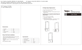
♦
In addition to the JTAG connection, access to the xPico 240/250 UART is required for
transmitter and receiver certification tests. Lantronix suggests adding a stuff option to
the serial port if the serial port is connected to another device. An example of this
connection is shown below. This will allow the certification lab to break into the module
UART lines and directly control the module UART during continuous mode testing for
certification.

xPico
®
200 Certification Firmware Instructions 7
Figure 1: Recommended Stuff Option for Transmitter Certification Tests
Stuff option components
Stuff option components
xPico
240/
250
Module
JTAG
Port
Customer MCU
External DB9
serial port
RS232
Serial
transceiver
Resistors
Resistors
UART
UART
JTAG
See the evaluation board schematic and artwork for recommended transceiver, DB9, and JTAG
port connections in the xPico 200 Series Evaluation Kit User Guide.
Wi-Fi Continuous Mode Software Installation
First download the Wi-Fi continuous mode software to use the module for continuous mode
testing for certification. Once downloaded and powered up, you will no longer be able to load the
standard Lantronix firmware and the module can only be used for continuous mode testing for
certification.
1. Download the xPico 200 continuous mode software at
https://www.lantronix.com/products/xpico-200/#docs-downloads/
.
2. Copy the xPico200_continuous_tx directory to the desktop of your PC.
3. Connect the Olimex ARM_USB_Tiny_H adapter to your PC and UUT.
Note: You will need the Tag-Connect adapter and cable to connect your Olimex to
the JTAG port on the evaluation board. Required Tag Connect part numbers
TC2050-ARM2010 and TC2050-IDC
4. Install the appropriate Zadig driver for the Olimex on your PC.
5. Open a command prompt and CD to this directory:
\Desktop\xPico200_continuous_tx\firmware-711_NVRAM
6. Power up the unit and run the loadfw.bat script to load the continuous mode firmware.

xPico
®
200 Certification Firmware Instructions 8
Figure 2: Wi-Fi Continuous Mode Software Installation
Running the Wi-Fi Continuous Mode Tests
Run the Lantronix xPico 200 continuous mode scripts using the steps below. These scripts are
based on the Cypress WL tool commands for the Cypress processor inside of the xPico 200
module. For more information on WL tool commands please see the Cypress reference
document at http://www.cypress.com/file/385966/download
.
1. Open up a command prompt and CD to the directory below. This directory has the
scripts you will need to start and stop the transmit tests.
..\Desktop\xPico200_continuous_tx\wl_tool\scripts
Figure 3: CD to Scripts Directory

xPico
®
200 Certification Firmware Instructions 9
2. Edit the .bat files as necessary to change the bit rate and channel number.
3. On all of the script files you will need to edit the file to call out your serial port. The line
below sets the serial port. The example below shows the serial port is set to COM3.
set comport=%1 3
4. The command below sets the channel which is the entry after the -c item. The example
below utilizes 36.
..\wl%target% --serial %comport% chanspec -c 36 -b 5 -w 20 -s 0
Notes:
– For the -c item use the desired channel for your test. A full channel listing is provided in
the compliance section of the data sheet.
– The -w item changes the bandwidth, either 20 or 40.
– The -b item sets the band, either 2 or 5 for 2.4 Ghz and 5 Ghz.
– You should not need to change the bandwidth or band in the batch files as separate script
files are included for each band and bandwidth.
5. Edit the line below in the files to change the bit rate.
..\wl%target% --serial %comport% nrate -r 54
This line is for 80211a/g
rates.
Acceptable values
1,2,5.5,11, 6, 9, 12, 18,
24, 36, 48, 54
..\wl%target% --serial %comport% nrate -m 0
This line is for 802.11n
rates.
Acceptable values 0 to 7.
6. To run a script at the command prompt, type the file name of the script. For example,
running the 802.11a transmit script type tx_80211a_start.bat at the command
prompt.

xPico
®
200 Certification Firmware Instructions 10
7. To stop the transmit use the 0.tx_80211_stop.bat script.
8. RX tests can be done with the rx_80211.bat script.
9. Carrier only tests use the tx_carrier_start.bat script.
Table 1: Full Wi-Fi Test Script Listing
Script Purpose
0.tx_80211_stop.bat
Stops 802.11 transmitter tests.
0.tx_carrier_stop.bat
Stops the transmitter carrier tests.
rx_802112g.bat
Starts the 802.11 2.4Ghz receive mode test.
rx_802115g
Starts the 802.11 5Ghz receive mode test.
tx_80211a_start
Starts the 802.11a transmitter test.
tx_80211b_start
Starts the 802.11b transmitter test.
tx_80211g_start
Starts the 802.11g transmitter test.
tx_802112n20_start
Starts the 802.11n 2.4 Ghz, 20 Mhz bandwidth transmitter test.
tx_802115n20_start
Starts the 802.11n 5 Ghz, 20 Mhz Bandwidth transmitter test.
tx_802115n40_start
Starts the 802.11n 5 Ghz, 40 Mhz Bandwidth transmitter test.
tx_carrier2g_start
Starts the 802.11 2.4 Ghz carrier only test.
tx_carrier5g_start
Starts the 802.11 5 Ghz carrier only test.

xPico
®
200 Certification Firmware Instructions 11
Bluetooth Continuous Mode Testing
The steps in http://www.cypress.com/file/298091/download describe how to run the Lantronix
xPico 200 Bluetooth continuous mode scripts. These scripts are based on the Cypress
mybluetool commands for the Cypress processor inside of the xPico 200 module.
Loading BT Continuous Firmware
Download the continuous mode BT firmware using the same process as used to load the
continuous Wi-Fi firmware. Once downloaded and powered up, you will no longer be able to load
the standard Lantronix firmware and the module can only be used for continuous mode testing for
certification.
1. Download the xPico 200 continuous mode software at
https://www.lantronix.com/products/xpico-200/#docs-downloads/
.
2. Copy the xPico200_bt_test directory to the desktop on your PC.
3. Connect the Olimex ARM_USB_Tiny_H adapter to your PC and UUT.
Note: You will need the Tag-Connect adapter and cable to connect your Olimex to
the JTAG port on the evaluation board. Required Tag Connect part numbers
TC2050-ARM2010 and TC2050-IDC.
4. Install the appropriate Zadig driver for the Olimex on your PC.
5. Open a command prompt and CD to directory:
..\Desktop\xPico200_bt_test\bt
6. Power up the unit and run the loadfw.bat script to load the continuous mode
firmware.
Running the BT Test Modes
1. Follow the instructions for each type of test in the Cypress document:
http://www.cypress.com/file/298091/download
2. You will need to set the COM port to the COM port on your PC
set MBT_COM_PORT=COMxx (where COMxx is the comport on your PC)
set MBT_BAUD_RATE=3000000 (this should equal the baud rate for your COM port)
3. Power up the unit.
4. Assert the module reset pin and then wait 10 seconds.
5. Run the mbt reset command to reset the unit.
6. Make sure the reset command results with success per the message example for the
reset test in the Cypress document.
7. Choose which of the BT tests you need to run and follow the command sequences in the
Cypress document.

xPico
®
200 Certification Firmware Instructions 12
Table 2: BT Test Commands
BT Test Command Description
mbt reset
This command resets the BT device on the module.
Run this prior to running any other certification test.
Also, can be used to stop any of the running BT tests.
mbt le_receiver_test <rx_channel>
This command runs the le receiver test.
rx_channel = receive frequency minus 2402 divided
by 2.
Acceptable channels are 0 to 39 where 0 is 2402Mhz
and 39 is 2480 Mhz.
mbt le_transmitter_test
<tx_channel> <data_length>
<data_pattern>
This command runs the LE transmit test.
tx_channel = receive frequency minus 2402 divided
by 2.
Acceptable channels are 0 to 39 where 0 is 2402 Mhz
and 39 is 2480 Mhz.
Data_length acceptable values are 0 to 37.
Data_pattern acceptable values are 0 to 7.
Data Pattern Definitions
0: Pseudo-random bit sequence 9
1: Pattern of alternating bits: 11110000
2: Pattern of alternating bits: 10101010
3: Pseudo-random bit sequence 15
4: Pattern of all 1s
5: Pattern of all 0s
6: Pattern of alternating bits: 00001111
7: Pattern of alternating bits: 0101
mbt le_test_end
The LE test end script stops the LE transmitter or LE
receiver tests.

xPico
®
200 Certification Firmware Instructions 13
BT Test Command Description
mbt tx_frequency_arm <carrier
On/Off> <tx_frequency> <tx_mode>
<tx_modulation_type> <tx_power>
This test turns on or off the transmitter carrier.
carrier on/off:
1: carrier on
0: carrier off
tx_frequency: 2402 MHz to 2480 MHz
tx_mode: selects unmodulated or modulated with
pattern
0: Unmodulated
1: PRBS9
2: PRBS15
3: All Zeros
4: All Ones
5: Incrementing Symbols
tx_modulation_type: selects 1 Mbps, 2 Mbps, or
3 Mbps modulation. Ignored if mode is unmodulated.
0: GFSK
1: QPSK
2: 8PSK
3: LE
tx_power: –25 dBm to +13 dBm
mbt receive_only <rx_frequency>
This test instructs the BT radio to receive on a specific
frequency.
Rx_frequency: 2402 to 2480

xPico
®
200 Certification Firmware Instructions 14
BT Test Command Description
mbt radio_tx_test <bd_addr>
<frequency> <modulation_type>
<logical_channel> <bb_packet_type>
<packet_length> <tx_power>
This command runs the connectionless transmitter
test.
bd_addr: BD_ADDR of Tx device (6 bytes), for
example 00112233445566
frequency: Set to 0 to use a normal Bluetooth hopping
sequence, or 2402 MHz to 2480 MHz to transmit on a
specified frequency without hopping.
modulation_type: Sets the data pattern
0: 0x00 8-bit Pattern
1: 0xFF 8-bit Pattern
2: 0xAA 8-bit Pattern
3: 0xF0 8-bit Pattern
4: PRBS9 Pattern
logical_channel: Sets logical channel to Basic Rate
(BR) or Enhanced Data Rate (EDR) for ACL packets.
0: EDR
1: BR
bb_packet_type: Baseband packet type to use
3: DM1
4: DH1/2-DH1
8: 3-DH1
10: DM3/2-DH3
11: DH3/3-DH3
14: DM5/2-DH5
15: DH5/3-DH5
packet_length: 0 to 65535. The device will limit the
maximum packet length based on the baseband
packet .
type. For example, if DM1 packets are sent, the
maximum packet size is 17 bytes.
tx_power: –25 dBm to +3 dBm

xPico
®
200 Certification Firmware Instructions 15
BT Test Command Description
mbt radio_rx_test <bd_addr>
<frequency> <modulation_type>
<logical_channel> <bb_packet_type>
< packet_length>
This test sets the BT radio to receive on a specific
frequency and sends reports about received packets.
bd_addr: BD_ADDR for the remote Tx device (6
bytes)
frequency: Frequency to listen to from 2402 MHz to
2480 MHz
modulation_type: Sets the data pattern to compare
received data
0: 0x00 8-bit pattern
1: 0xFF 8-bit pattern
2: 0xAA 8-bit pattern
3: 0xF0 8-bit pattern
4: PRBS9 pattern
logical_channel: Sets the logical channel to BR or
EDR for ACL packets
0: EDR
1: BR
bb_packet_type: Sets the packet type of the expected
packets
3: DM1
4: DH1/2-DH1
8: 3-DH1
10: DM3/ 2-DH3
11: DH3/3-DH3
14: DM5/2-DH5
15: DH5/3-DH5
packet_length: 0 to 65535. The device compares the
length of the received packets with the specified
packet_length.

xPico
®
200 Certification Firmware Instructions 16
BT Test Command Description
mbt
connectionless_dut_loopback_mode
COMx
This command sets up a connectionless loopback test
with an external tester for analyzing both RX and TX.
Once the connectionless command is entered the unit
will prompt for the interactive arguments below.
Remote_Device_BD_ADDR: BD_ADDR of the remote
transmitting device. [Size: 6 bytes]
LT_ADDR: The logical transport address of the BT
link. [Size: 1 byte] [Range: 0x01 - 0x07]
Number_Of_Tests: The number of tests to be
=executed. [Size: 1 byte] [Range: 0x01 - 0x10]
The following arguments repeat depending on the
number of tests:
Retry Offset: When a timeout occurs, subtract the
offset to go back to the earlier test.
[Size: 6 bits {31:26} in little endian uint32]
[Range: 0x01 - 0x3f].
Number_Packets: Number of packets to be received
for this test.
[Size: 15 bits {25:11} in little endian uint32]
[Range: 0x01 - 0x7fff].
TxPowerIndex: Power table index to use.
[Size: 3 bits {10:8} in little endian uint32]
[Range: 0x00 - 0x07].
RxChannel: Frequency offset in MHz from 2402 MHz.
[Size: 7bits {7:1} in little endian uint32]
[Range: 0x00 - 0x7f].
Packet Table Type: Defines the type of the packet.
[Size: 1bit {0:0} in little endian uint32].
0x0: Basic Rate Packet Types
0x1: EDR packet types
Retry Time Out: The time required to retry.
[Size: 1 byte] [Range: 0x01 - 0xff].
Test Scenarios:
[Size: 1 byte].
0x0: RX-TX Loop Back Mode
0x1: RX only with BER stats.
/