Page is loading ...

©2018 American Changer
Manual Bill/Note Breaker Series 060118
American Changer
American Changer
1400 N.W. 65th Place, Ft. Lauderdale, FL 33309
Tel (954) 917-3009 • Fax (954) 917-3079
www.americanchanger.com www.hoffmanmint.com
Bill/Note Breaker
Series
Installation, Operation,
and Service Manual
Changing the Industry℠
Installers & Service Technicians
Read and understand the instructions
detailed in this manual.
Owners & Operators
Keep this manual in a safe place to
provide to any service technicians
working on this machine.
Models: AC7702, AC7705, AC7712, AC7715,
AC7802, AC7805, AC7812, and AC7815

2

1
Table of Contents
Section 1 – Product Overview
1.1 – Machine Specifications……………………………………………………………………………………………………………..
2
1.2 – Warranty Information……………………………………………………………………………………………………………….
2
1.3 – Machine Safety…………………………………………………………………………………………………………………………
3
Section 2 – Setup & Installation
2.1 – Setup…………………………………………………………………………………………………………………………………………
5
2.2 – Mounting Instructions……………………………………………………………………………………………………………….
6
Section 3 – Operational Overview
3.1 – Component Description…………………………………………………………………………………………………………..
8
3.2 – Functional Description……………………………………………………………………………………………………………..
11
3.3 – Out-of-Service Conditions & Error Codes…………………………………………………………………………………
11
3.4 – Programming Menu…………………………………………………………………………………………………………………
15
3.5 – Remote Loading Software to the Flex-2 Board…………………………………………………………………………..
19
Section 4 – Maintenance
4.1 – Coin Hopper Maintenance………………………………………………………………………………………………………..
20
4.2 – Bill Validator Maintenance……………..…………………………………………………………………………………………
21
4.3 – LCDM1000 Bill Dispenser Maintenance.……………………………………………………………………………………
25
4.4 – LCDM2000 Bill Dispenser Maintenance…………………………………………………………………………………….
40
4.5 – Warranty Terms and Conditions………………………………………………………………………………………………..
55
©2018 American Changer
All rights reserved. No part of this work covered by
copyrights herein may be reproduced or copied in any
form or by means – graphic, electronic or mechanical,
including photocopying, recording, taping or information
storage and retrieval systems – without the written
permission of American Changer

2
Section 1 – Product Overview
1.1 – Machine Specifications
Operating Voltage (selectable by switch on power
supply)
Set at 115VAC: 90 ~ 132VAC 4.0A
Set at 230VAC: 180 ~ 264VAC 6.0A
Power Consumption
Controller: 10W Max
Puloon Bill Dispenser: 120W Max
Bill Validator: 50W Max
Operating Temperature
41°F to 104°F / 5°C to 40°C
Interface to Coin Hopper
24VDC, 2.5 amps max
*Note: Specifications stated herein may vary without notice. Capacities are approximations and may
vary.
1.2 – Warranty Information
PLEASE REFERENCE SECTION 4.5 ON PAGES 55 AND 56 FOR AMERICAN CHANGER’S DETAILED LIMITED
WARRANTY AND EXCLUSIVE REMEDIES. SOME HIGHLIGHTS FROM SAID SECTION ARE:
Coin Hopper(s), Coin Acceptors and Logic Board
These items are warranted for one year from date of purchase.
Banknote Validator
This item is warranted for two years from the date of purchase.
COVERED
• Manufacturers’ defects in workmanship or materials
NOT COVERED
• Damage caused by shipping or physical abuse
• Misapplication
• Vandalism
• End users’ attempt, on their own, to repair components
• Cleaning and maintenance
• Power surges and lightning strikes
A Return Material Authorization number (RMA #) must be obtained from American Changer
Corporation before returning a unit for repair; warranty or otherwise. A copy of invoices must
accompany any and all warranty work.

3
Section 1.3 – Machine Safety
Your safety and the safety of others are very important to
American Changer.
We have provided important safety messages in this manual and on your machine. Always read and
obey all safety messages.
All safety messages will tell you what the potential hazard is, tell you how reduce the risk of injury, and
tell you what can happen if the instructions are not followed.
This is a safety alert symbol.
This symbol alerts you to potential hazards that can kill or hurt you and others.
All safety messages will follow the safety alert symbol and either “DANGER”,
“WARNING”, or “CAUTION”.
These words mean:
You can be killed or seriously injured if you don’t immediately
follow instructions
You can be killed or seriously injured if you don’t follow
instructions
You can be injured if you don’t follow instructions
Distributors, retailers, operators, and/or service people are to insure the following warning label is
properly affixed on the ACC products to which you/they are using and/or servicing in order to help
meet the applicable Proposition 65 requirements. For more information go to
www.P65Warnings.ca.gov

4
Important Safety Instructions
DANGER: To reduce the risks of severe injury
secure the machine to a stable structure.
WARNING: To reduce the risk of electrical shock,
disconnect all electrical power to the machine
before servicing.
NOTICE: For indoor use only.
NOTICE: Ensure this machine is level when
installed
SAVE THESE INSTRUCTIONS
American Changer does not guarantee machines (products) or services to be 100% secure against criminal
attempts. All machines (products) and services are to be used in accordance with business best practices and the
owner’s or operator’s best judgement.
Installation, use, service and maintenance must be performed in accordance with applicable machine (product)
manuals provided by American Changer and comply with any and all pertinent laws or regulations.
Inspect your machine (product), at a minimum annually, by a qualified service technician.
Dimensions and weights are reasonably close estimates. Specifications in this manual can vary without notice.

5
Section 2 – Setup & Installation
2.1 – Setup
NOTICE: THIS MODEL MACHINE IS FOR INDOOR USE ONLY.
Inspect for any connectors or components that may have been dislodged during shipping. The lock and keys for
your changer will be inside the manila envelope along with this manual and other pertinent information. To install
the lock, insert the cylinder into the hole in the middle of the T-handle and push until it stops. Turn the key until
you hear it “snap." Turn the key counterclockwise ¼ turn and remove the keys.
NOTE: The only way to get a duplicate set of keys made is to save the tag that comes with the keys. The ID #
begins with “AC” or “ACC” followed by digits.” If you purchased Medeco locks with your machine the ID will
begin with “7RA” followed by digits.”
CHECKING SHIPMENT: Be sure to check the shipment against the Bill of Lading for shortages. Also, check for
external damage to the packaging. Note any shortages and/or damage to the packaging on the Bill of Lading in
the presence of the carrier and ask the carrier to initial on the Bill of Lading accordingly. Immediately report any
shortages or damage to the packaging to the carrier and American Changer.
TEST: Before permanently installing the changer, do a functional test to verify that there is no shipping damage to
your new changer.
Plug the power cord into a dedicated, grounded 220VAC outlet. The machine is preset to accept 10p, 20p, 50p,
£1 and £2 coins and dispense 2p coins (unless otherwise specified at the time of purchase).
Fill each of the coin hoppers with a minimum of 100 coins. On the Main Logic Board, turn the switch on the
bottom right corner “ON.” The rocker switch has an “I” and “O” printed on it. When the “I” is pressed down, the
changer is “ON.”
If the machine does not function properly please contact American Changer’s Technical Support Department at
service@americanchanger.com or 1-888-741-9840.

6
2.2 – Mounting Instructions
This machine must be installed in accordance with local codes. If you are unsure in any way what your
local codes are or unsure of anything in the following steps, please hire a licensed professional to
mount your machine.
1. Disconnect any and all AC power going to the machine. (Unplug AC line cord from the rear of the
machine.)
2. Note: You will need to verify with the building code enforcement to see if it is allowable to plug the
changer into a grounded outlet. If it is not, there must be 220VAC run through conduit or other
means to meet local codes to the changer. If it is not required, proceed to step #6.
3. Have a licensed electrician run the conduit, install the new breaker, wire and help decide how the
wiring will enter the changer (from the back or the bottom).
4. After the conduit has been installed, proceed with securing the machine to a stable structure.
5. Find an appropriate stable structure which to secure the machine to.
6. NOTICE: BEFORE SECURING ENSURE THE MACHINE IS LEVEL.

7
7. : PROPERLY SECURE MACHINE (PRODUCT) TO THE FLOOR SO THE MACHINE
(PRODUCT) CANNOT BE MOVED OR TIPPED. USE STRUCTURAL SOUND FASTENERS THAT CAN BE
PROPERLY TIGHTENED AND SECURE THE MACHINE (PRODUCT) THROUGH EACH OF THE HOLES IN
THE BASE OF THE MACHINE (PRODUCT) TO THE APPLICABLE SURFACE TO WHICH IT IS BEING
SECURED.
8. Use the four holes located in the bottom of the cabinet to secure the machine to a stable structure.
9. Verify that the machine is properly secured to the stable structure.
10. Connect your AC line to the rear of the changer. Then plug it into the outlet.
a. Do not use an extension cord unless allowed by the building electrical code.
b. Installation is completed. Proceed to the “Programming the Changer” section.
The proper performance of your American Changer machine is directly related to the quality of the power it is
supplied. AC power fluctuations, including blackouts, brownouts, over voltages, sags, surges, and spikes may cause
the machine to miss pay. To ensure the most trouble-free operation, we strongly recommend plugging all of our
machines into a DEDICATED AC outlet (this means there are no other machines on location plugged into the same
AC line). A simple way to check if this is true is to turn off the breaker associated with our machine at the breaker
box. No other equipment on location should lose power.
Additionally, if your unit is located in an area prone to lightning storms or other sources of frequent power
disturbances, we also strongly recommend using an Uninterruptible Power Supply (UPS). If power is lost during a
payout to a customer, a UPS will allow your machines to complete the transaction that would otherwise not be
completed. In some cases, a UPS may also correct long-term under and/or over voltages on the AC line by
converting to the proper line voltage before the power reaches the machine.
Every American Changer machine has a surge suppressor built into the main logic board. This helps eliminate
power related noise problems, but it will not protect from substantial voltage spikes or nearby lightning strikes. If
this is a concern for your area, we recommend purchasing a commercial grade UPS with integrated surge
protection. NOTE: A POWER STRIP IS NOT A SURGE PROTECTOR.

8
Section 3 – Operational Overview
3.1 – Component Description
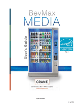
Coin Hopper
The hopper uses the ccTalk communication protocol. It can dispense coins or tokens ranging in size from
21.01mm to 30mm in diameter and 1.25mm to 3.30mm in thickness. An option is available to dispense
smaller coins. This machine’s coin capacity is approximately 45,000 25mm diameter coins.
Bill Validator
This model machine may have been sold without a bill validator. It is intended to work with a 24VDC bill
validator using the MDB protocol.
6-Pin (MDB) Connector Pinout:
Pin #1 - +24VDC Power
Pin #2 - DC Power return
Pin #3 - Not Used
Pin #4 - Master Receive
Pin #5 - Master Transmit
Pin #6 - Communications Common
Put coins into this opening
Coin Counting Optic
Motor
12-Pin female connector
(located in rear of hopper)
6-Pin (MDB)
4
1
6
3

9
Flex Programmer Board
This device is used to view and edit the machine’s settings. When in normal operation the Flex
Programmer Board displays payout information to the person using the machine.
Flex-2 Main Logic Board
Connection to
Flex-2 Main
Logic Board
Flex Programmer
Board
Bill
Validator
24VDC Power
Input
Select Switch for
accessing the
programming
menu
SD Card
On/Off
Switch
Bill Dispenser
Communication

10
Bill Dispenser
The bill dispenser can dispense bills ranging in size from 100mm to 162mm wide and 62mm to 78mm
high. This machine’s bill capacity is approximately 1000 per cassette.
LCDM1000
LCDM2000
Single Denomination Dispenser
Dual Denomination Dispenser
Located in the rear of the dispenser
Located in the rear of the dispenser
24VDC Power
Input
Bill Dispenser
Communication
24VDC Power
Input
Bill Dispenser
Communication

11
3.2 – Functional Description
1. Dispense
The machine dispenses bills and/or coins.
2. Payment
The machine accepts payment in the form of cash only.
3.3 – Out-of-Service Conditions & Error Codes
System
Failures
Below are conditions that will cause the machine to go into
an “Out-of-Service” mode. The message “Temporarily out
of Service” will be displayed on the external LCD display
when the machine is in an “Out-of-Service” mode.
Note: These error messages can only be viewed by using
the Flex Programmer Board.
Bill Validator
Bill Validator Error Conditions
Motor
Validator stacker/transport motor has failed
Sensor
Sensor failure
CheckSum
Indicates error with file stored on validator main board
Jammed
A bill or debris is jammed in the validator bill path
Cashbox
The cashbox is not installed on the bill validator
No Comm.
The Flex-2 main logic board is unable to communicate with
the bill validator.
Can’t
Enable
The Flex-2 main logic board has tried to enable the
validator several times without success.
Coin Hopper
Coin Hopper Error Conditions
Opto’s
Indicates the coin counting optic is blocked.
No Comm.
The Flex-2 main logic board is unable to communicate with
the coin hopper.
High
Current
The hopper motor exceeded its maximum current rating.

12
Low
The amount of coins in the coin hopper is below its
operational threshold.
Timed Out
The coin hopper did not complete a payout in its allotted
time frame.
Coin
Acceptor
Coin Acceptor Error Conditions
Credit Sns.
Credit sensor blockage or failure
Piezo Sns.
Piezo sensor blockage or failure
Exit Sns.
Exit sensor blockage or failure
Reject Sns.
Reject sensor blockage or failure
Return
Mech
Unit failure. Needs to be replaced.
Thermistor
Thermistor failure
No Comm
The Flex-2 main logic board is unable to communicate with
the coin acceptor.
Programmer
Flex Programmer Board Error Conditions
No Comm
The Flex-2 main logic board is unable to communicate with
the Flex Programmer Board.
Disabled
The use of a secondary display is not enabled.
Enabled
The use of a secondary display is enabled.
Bill
Dispenser
Bill Dispenser Error Conditions
Clear these errors by resetting counts
Rjct
Bin>100
The reject bin exceeded the 100 notes capacity
High Limit
The set max limit of the high cassette has reached capacity
Mid Limit
The set max limit of the middle cassette has reached
capacity

13
Clear these errors by printing the status information
Hgh Csst
Low
Low bill sensor of the high cassette has been triggered
Mid Csst
Low
Low bill sensor of the middle cassette has been triggered
Dspns
Issue!
The unit tried 10 times to dispense and failed
No Comm2
CDM
No communication with the ezCDM 1000.
Counter
Disagreement of the pick and eject counts
Eject
Sensor
Abnormal detection of note at eject sensor after
dispensing notes
Reject Rate
If more than eight notes are rejected
Eject Init
Eject sensor error
Pck/Ejct
Hgh
A note was picked from the high cassette and failed to
dispense
Pck/Ejct
Mid
A note was picked from the middle cassette and failed to
dispense
Pick Failure
Failed to pick bill
These errors must be serviced by checking the bill
dispenser
No Comm1
CDM
No communication from Bill dispenser, Check USB Port 2
for RS232 device!
Distance
Distance between notes in the path is out of range
Feed
Sensor
Check feed sensor
Delay Eject
Eject sensor error during dispensing notes
Wheel Cntr
BLDC motor exceed speed limit
Expansion
Tm
Delay at (Expansion module 1,2 -> DM)

14
MOTD
Initial
The initial value of the MOTD is out of range
Diverter
Diverter Solenoid Error
MOTD 2F
The initial value of the MOTD is out of range during
dispensing notes
Irreg cmnd
Irregular command
Purge Time
Purge timeout error
Currency
Set
There is no information of currency. Host did not provide
currency information
DM Fd Snsr
DM feed sensor error
DM
Timeout
Delay at delivery direction (DM->Eject or Reject Sensor)
Count
Ovrflw
A detection of the abnormal counts is more than a
allowable value of notes dispensed
at one transaction
Bad Comm
CDM
An excess of bad data is being transmitted between
controller board and ezCDM
Ejct Snsr 81
Eject sensor is blocked
Rjct Snsr
81
Reject sensor is blocked
Potentmtr
81
Abnormal operation with the potentiometer
Solenoid
OFF
Solenoid is OFF
High Snsr
81
Feed sensor in the high cassette is blocked
Mid Snsr
81
Feed sensor in the middle cassette is blocked

15
3.4 – Programming Menu
To enter the programming menu, begin by pressing the “Select Switch” on the Flex-2 main logic board.
Pressing the select switch will bring the display to show “Enter Access Code.”
Use the Flex Programmer Board to enter the access code. The default code from the factory is “1234”
To exit the programming menu or the “Enter Access Code” screens press the “Select Switch”
Use the Flex Programmer Board to navigate the menus. Press the “Cancel” button and enter a menu
number to be brought immediately to that menu or press the Back/Next button to step through the
menus.
All the menus work the same:
No/Yes: Selects status
Back/Next: Selects the item
Exit: Exits the setup menu
NOTE: ALL MENUS MAY NOT APPLY TO YOUR SPECIFIC MODEL MACHINE. UNUSED MENUS WILL BE
IDENTIFIED BY AN ASTERISK *.
Menu 01 – Print Help Menu
A list of the menus and their corresponding numbers is printed by the external printer.
Menu 02 – System Info
The payout information and configuration settings are printed by the external printer. Aside from those,
the following information is also included in the System Info printout:
Software Revision
Valid1 Status
Valid2 Status
Hopper #1 Status
Hopper #2 Status
Hopper #3 Status
Hopper #4 Status
Credit Status
Printer Status
Coin Acceptor
Bill Dispenser
Temperature Info
WebServer Info
Menu 03 – Button Price*
Define the amount charged for each selection (1-4).
Menu 04 – Button Payout*
Sets up payout count for the 4 selection buttons.

16
Menu 05 – Enable Bill
This system only uses MDB validators. Depending on what type of MDB validator is used, the display will
only toggle between the denominations accepted by the bill validator.
Menu 06 – Payout Table
Only bills enabled in Menu 05 will be available in this menu. Enter the # of items dispensed for each bill
denomination.
Menu 07 – Enable Hoppers
Enable or disable hoppers 1, 2, 3 and/or 4.
Menu 08 – Hopper Coin Value
Set the value of the coin being dispensed. Used only when providing tokens with change or when
selections are not in use.
Menu 09 – Enable Coin Acceptor
Select between a Pulse or ccTalk coin acceptor. Enable or disable the coin acceptor.
Pulse – Enable → High or Low
ccTalk – Enable → Coin Values
Menu 10 – System Disable
Disables the machine if any of the selected devices goes offline.
Hopper 1
Hopper 2
CassetteU
CassetteL
ccTalk coin acceptor
Menu 11 – Promo-Token Payout*
Enter the # of items paid for each promotional token.
Menu 12 – Dump Hoppers
Dumps the coins from all hoppers. A receipt is printed by the external printer.
Menu 13 – Audit Information
Prints a summary of all the sales. There are separate counters for tokens dispensed from each hopper.
Reset – Prints 2 copies of all the audit values and resets all the “Resettable Counters” to 0.
Every time Reset button is pushed the audit sequence number increases by one.
Print – Pushing the Print button prints all the audit values without resetting.
All the values are max 99,999 except for the Total Cash value which is $100,000.00.
Menu 14 – Vend Item Name*
Choose from Items, Tickets or Tokens.

17
Menu 15 – Date Setup
Enter the date in this format: 20YY-MM-DD.
Menu 16 – Time Setup
Enter the time in this format: HH:MM. 24 hour format.
Menu 17 – Machine Number
Assign a machine number that will appear in audit report print out.
Menu 18 – Marquee Timer*
Setup a time to turn On/OFF the marquee.
Menu 19 – Zip Code Enable*
Enable or disable zip code verification for credit card transactions.
Menu 20 – Access Code
Change the access code.
Menu 21 – Key Beep Enable*
Enable or disable beep when a button is pressed.
Menu 22 – Location Name
Enter location name to print on credit card receipts.
Menu 23 – Bills Loaded Cassette Upper
Enter number of bills loaded in the upper cassette. If this number is zero the machine will use the Bill
Dispenser’s low bill sensor instead.
Menu 24 – Bills Loaded Cassette Lower
Enter number of bills loaded in the lower cassette. If this number is zero the machine will use the Bill
Dispenser’s low bill sensor instead.
Menu 25 – Bill Value Cassette Upper
Enter the value of the bill being dispensed from the upper cassette.
Menu 26 – Bill Value Cassette Lower
Enter the value of the bill being dispensed from the lower cassette.
Menu 27 – Printer Options*
Menu 28 – Validator Enable
Enable or disable the bank note validator.
Menu 29 – Nayax Test Mode*
Menu 30 – Country*
Select between U.S and U.K. Selecting U.S. displays “$”. Selecting U.K. displays “£” and “p”.

18
Menu 31 – Webserver*
The Webserver IP configuration is displayed.
Menu 32 – Minimum Credit*
Enter a minimum value for credit card transactions.
Menu 33 – Anti Stringing
Setup a maximum cash amount, maximum time and shut-off time for anti- stringing purposes.
Menu 34 – Programmer
Enable or disable dual display mode. In dual display mode the Flex Programmer Board is able to be used
as a secondary display to access the programming menu.
/