Page is loading ...

Trouble Shooting
DWG No. 990 - 1 1 - 0 6 - 01
Date 97- 02
Europe Bill Acceptor
EBA - 10 - SD2
CHAPTER 6

.
Many troubles of the validator are caused by minor reasons. Before replacing any
part, be sure to check whether connectors are connected properly and there is no
line breakage in a cable harness.
If the validator rejects a bill frequently, the magnetic head and magnetic head
roller may have a layer of iron particles on them. Clean these areas.
. Observe the operating conditions of the validator carefully when you turn on the
power. This is important for the detection of a trouble cause and defective
location.
Whenever you disassemble and repair the validator head, be sure to adjust the
ensors.
Perform repairs in accordance with Chapter 7, "Adjustment Manual Performance
Test",Chapter4,"WiringDiagram",andChapter4,"DisassemblyProcedure". 2
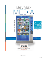
Introduction

Connect the 25-pin flat cable
to the acceptor.
Connect EBA and VM-450 in the following manner.
2 Connecting the EBA and VM-450
1- Outline of troubleshooting
EBA can find a trouble cause by performing the "bill identification operation test".
Theperformance test or sensor adjustment is performed according to the identified
troublecause and the necessary repairs and replacement of parts are performed. VM-450
Investigation of trouble cause
Investigation of trouble cause

3-1 To perform the bill identification operation test, first set the acceptor to the test mode
standby status. Set the DIP switches of EBA-1 0/41 0 and VM-450 as shown in the figure
below. Make sure to turn off VM-450 before changing the DIP switch
3 Bill Identification Operation Test Procedure
3-2 When you turn on the power of VM-450, the BSY LED lights and "_000__ 00" will
appear on the segment display.
At this time, the DIP switch next to the LED of EBA will light.
This is called the best mode standby status. You can perform operation test in this status.
VM -450 currency type signal indication
LED light
VEND 1
Currency type
VM - 450
BSY VEND1 VEND2 VEND3
Currency type 1
Currency type 2
Currency type 3
Currency type 4
Currency type 5
Currency type 6
VEND 2
VEND 3
EBA-10/410 DIP switch setting
OFF
OFF
3-3 Executing the identification operation tests
Set the DIP switch of the acceptor as shown in the figure below.
3-4 When you turn off DIP switch No. 1 of the acceptor, the acceptor can receive a
bill and you can confirm the bill receiving rate after the intial operation is
completed.
VM.450 indates that the bill is received and the type of currency is indicated by
means of the VEND1 to VEND3 LED combinations.
bill
completed
SD2 Acceptor with stacker
EBA-10/410 DIP switch setting
SD2 Acceptor without stacker
EBA-10/410 DIP switch setting

Do not use bills like the ones below to confirm the bill receiving operation. If you insert such a bill it will
not be identified properly.
(a) Bills that are dirty, worn, wet, torn, and badly wrinkled.
(b) Bills with folded and overlapped corners or edges.
(c) Bills that have considerably different cutting dimensions and printing displacement.
(d) Bills that are stained or have iron particles on them.
4 EBA Trouble Indication and Bill Rejection Trouble Indication
4-1 When the EBA cannot store the bills successfully, the LED on the CPU board will
flash as shown in the figure below. You can determine the trouble by confirming the
flashing condition and number of times the LED flashes.
(a) The bill is not accepted
(b) After the bill is received, it is rejected.
Acceptor identification unit error. The LED on the CPU board flashes rapidly. Check the
number of times the LED flashes and see 6 "Error Code (Rejecting a Bill) List".
EBA operation erroe. The LED on the CPU board flashes slowly. Check the number
of times the LED flashes and see 6 "Error Code (Malfunction) List".
Check now the LED flashes
(a) Malfunction - LED flashes slowly
(b) Rejection - LED flashes rapidly.

5 Trouble Classification
The trouble causes are mainly divided into the following 6 types. Check the
operating conditions.

(1) Test mode can not be started.
(2) Indication LED does not turn on.
(3) Normal signal can not be send from acceptor to controller.

(4) Bill is rejected and rate of receiving bills is poor.
Check whether the ROM being
used complies with the country
corresponding to the currency.
*1: See Chapter 7, "Adjusment Manual" for details about the sensor adjustment.
*2: Determine the defective position from 6 " Error Message" in the Adjusment Manual
and replace the parts as required.
(5) Bill is not fed smoothly. (Jammed in feed route.)
Repair or replace the
required parts, or adjust
the sensor.

(6) Bill is not accepted. The LED next to the DIP switch flashes repeatedly. ( Stop state due to
malfunction )
*1: See Chapter 7, " Adjustment Manual" for details about the sensor adjustment.
Performance test
Check 3-(1) (Acceptor forward rotation test)
Check 3-(2) (Acceptor forward rotation test)

6 Error Code (1) Error Code ( Malfunction ) List Slow flash
No. of times LED flashes Description of error
1 (1) Detected stacker full.
(2) Operation of the insertion slot unit is lagging.
2 (1) Insertion slot unit operation error.
(2) No signal is sent from the stacker home position sensor.
(3) No signal is sent from the stacker encoder.
3 (1) Bill stays in the stacker feed route.
(2) Feed operation of the stacker is disabled
4 (1) Bill stays in the acceptor.
5 Acceptor feed motor speed error.
6 (1) Acceptor motor was started but does not rotate.
(2) Acceptor motor was stopped but does not stop.
(3) No signal is sent from the acceptor encoder sensor.
7 Reserved.
8 Reserved.
9 (1) PB unit motor was started but does not rotate.
(2) PB unit motor was stopped but does not stop.
(3) No signal is sent from the home sensor the PB unit.
10 Reserved.
11 Stacker board extension port error
12 Sensor turned on at a timing impossible in normal operation.
(3) Error Code ( Rejecting a bill ) List Fast flash
No. of times LED flashes Description of error
1 Bill was inserted at crooked angle.
2 Magnetic sensor pattern error.
3 Bill stays in the acceptor feed route.
4 Photo sensor error 1.
5 Bill feed error.
6 Judgement error.
7 Photo sensor error 2.
8 Bill Photo sensor error 3.
9 Receiving inhibited bill was rejected.
10 Reject signal was input.
11 Lever sensor has detected an error.
12 Back sensor has detected an error.
13 Incorrect length bill.
14 Photo sensor error 4.
15 Photo sensor error 5.

Performance Test
/