Page is loading ...

565 manual September 2003
Part #74279
Printed in USA
1
TABLE OF CONTENTS
TABLE OF CONTENTS 1
Chapter 1 – YOUR NEW ORION
ORION –THE NEXT STEP IN TEN-TEC INNOVATION 4
UNPACKING YOUR NEW ORION 4
CONNECTING A POWER SUPPLY 4
A WORD ABOUT GROUNDING 5
HOW IS ORION DIFFERENT FROM OTHER HIGH-PERFORMANCE
HF TRANSCEIVERS? 5
Chapter 2 – ORION FRONT AND REAR PANEL CONTROLS AND THEIR FUNCTIONS
ANALOG METER 7
(1) POWER 7
(2 – 7) ANTENNA ASSIGNMENTS 7
(8 – 13) VFO ASSIGNMENTS 8
(14) MIC 9
(15) PHONES 10
(16) CW 11
(17) PWR 12
(18) MON 12
(19) SP 13
(20) SEND FUNCTIONS 13
(21) USER 1 AND USER 2 14
(22) RECALL 14
(23) NB 14
(24) NR 15
(25) NOTCH 15
(26) AN 15
(27) MODE 15
(28) PREAMP 16
(29) RF GAIN 16
(30) SPOT 16
(31) STEP 16
(32) SWEEP 16
(33) AGC 16
(34) ATTN 17
(35) MENUS 17
(36) AUDIO 17
(37) VOX 19
(38) S-TONE 19
(39) MIC 19
(40) TUNE 19
ALC 20
(41) PBT/BW ENCODER 21
(42) MULTI ENCODER 21
(43) HI CUT – LO CUT 21
(44) MAIN AF ENCODER 22
(45) SUB AF ENCODER 22
(46) RIT/XIT ENCODER 22
(47) MAIN TUNING KNOB “A” 22
(48) RIT 22
(49) VFO A>M 22
(50) and (51) LCK 23
(52) VFO B>M 23

565 manual September 2003
Part #74279
Printed in USA
2
(53) XIT 23
(54) MAIN TUNING KNOB “B” 23
(55) MAIN RX 23
(56) SUB RX 23
(57) FREQUENCY ENTRY AND BAND CHANGE BUTTONS 23
(58) VFO A ENTER 24
(59) VFO B ENTER 24
(60) A>B, B>A, A/B 24
(61) ANT 1 25
(62) ANT 2 25
(63) DC IN 25
(64) FUSE 25 A 25
(65) GND 25
(66) AMP KEY 1 26
(67) TX OUT 1 / TX EN 1 26
(68) AMP KEY 2 26
(69) TX OUT 2 / TX EN 2 26
(70) +13.8 VDC 27
(71) AUX RX 27
(72) XVRT KEY 27
(73) XVRT RF 27
(74) LINE OUT 27
(75) SPARE 27
(76) BAND DATA 1 27
(77) BAND DATA 2 27
(78) EXT SPKR 28
(79) KEY 28
(80) AUX I/O 28
(81) REMOTE 29
(82) SERIAL DATA 29
Chapter 3 – MENU SYSTEM
(TX) TX MENU 30
(CW) CW MENU 31
(VOX) VOX MENU 32
(RX) RX MENU 32
(OTHER) OTHER MENU 34
(SSB) SSB MENU 35
(FILTR) FILTER MENU 35
Chapter 4 – OPERATION AND ACCESSORY CONNECTION EXAMPLES
BASIC TRANSCEIVE OPERATION 37
OPERATING SPLIT FREQUENCY 37
OPERATING THE AUTOMATIC ANTENNA TUNER (IF INSTALLED) 38
CONNECTING AN EXTERNAL LINEAR AMPLIFIER 38
TUNING UP AN EXTERNAL LINEAR AMPLIFIER 39
FACTORS THAT AFFECT THE SOUND OF SSB TRANSMIT
AND THEIR ADJUSTMENT 39
SETTING UP ORION FOR AM TRANSMIT 42
FSK OPERATION 42
TRANSVERTER HOOKUPS 42
DIVERSITY RECEPTION 43
WEAK SIGNAL DX RECEPTION AND CONTEST OPERATION
AND THE ORION 44

565 manual September 2003
Part #74279
Printed in USA
3
EXTERNAL CW OUTPUT PLUS CW KEYER OPERATION
FROM PADDLES 47
DRAG ADJUSTMENT FOR MAIN TUNING KNOBS “A” AND “B” 47
MASTER RESET 47
UPGRADING ORION OVER THE INTERNET 48
TROUBLESHOOTING 48
Chapter 5 – SPECIFICATIONS AND TECHNICAL DESCRIPTION
SPECIFICATIONS 50
HARDWARE INFORMATION 54
SUBASSEMBLY LOCATION 54
SIGNAL PATH – MAIN RECEIVER 54
SIGNAL PATH – SUBRECEIVER 55
SIGNAL PATH – TRANSMITTER 55

565 manual September 2003
Part #74279
Printed in USA
4
Chapter 1 – YOUR NEW ORION
ORION –THE NEXT STEP IN TEN-TEC
INNOVATION
The Ten-Tec ORION represents the most
innovative HF transceiver ever created for
amateur radio use.
Our aim in designing and producing this
radio was to meet the demands of
increasingly intense competition in DX and
contesting, while adding many non-
performance related features that the active
ham can also appreciate. The features and
performance ORION brings to ham radio will
enhance HF radio contacts of all sorts, while
opening new possibilities for amateur radio
operation. ORION offers world-class
reception and transmission of CW, SSB,
digital modes, FM, and AM on all 10 HF
amateur bands, plus excellent general
coverage reception via the second (sub)
receiver from 100 kHz to 30 MHz.
UNPACKING YOUR NEW ORION
Examine ORION for signs of shipping
damage. Should any damage be apparent,
notify the delivering carrier immediately,
stating the full extent of the damage.
Retain all damaged cartons. Liability for
shipping damage rests with the carrier. We
recommend that you keep the carton and
fillers in the event that storage, moving, or
shipment becomes necessary.
The following hardware and accessories
come standard with your ORION. Make
sure that you have not overlooked anything.
Qty Part # Description
1#27074 Mini-ATC Blade
Fuse, 25 Amp.
1#35003 Phono Plug
1#35057 4-pin Microphone
Connector
1#35163 1/8 in. Stereo Plug
1#35165 2-pin Power
Connector Shell
2#41020 Female Power Pins
6 ft #46159 Wire, Red & Blk,
#12
1#35013 Phone Plug, 3-
circuit
1#35331 Shell, Band Data
Plug
15 #41068 Band Data Plug
Pins
1#38040 .050 Hex Wrench
1#38088 .062 Hex Wrench
138313 T10 Torx Wrench
1#46176 Accessory Cable.
5-pin DIN to Phono
F.
1#74020 Warranty Card
1#74279 User’s Manual
1#86095 DC Power Cord
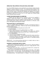
Figure 1-1 ORION Packing Kit
CONNECTING A POWER SUPPLY
The ORION transceiver requires a source of
well-filtered and regulated DC voltage. The
supply voltage can range from +12.8 to
+15.0 Vdc but +13.8 Vdc is the optimum
value. The voltage source must be capable
of supplying 22 amperes continuous duty.
We recommend using the included DC
power cable (P/N 86095). We have also
included spare connector pins (P/N 41020)
and a spare 2 pin power connector shell
(P/N 35165) for building your own cable.
The power supply plug will attach in only
one direction to the polarized two-pin DC
connector on ORION’s rear panel. Use no
less than #14 gauge (#12 recommended)
stranded wires for three-foot long
connections to accommodate the required
current demand during transmit. Use
heavier gauge wire for longer power supply
leads.

565 manual September 2003
Part #74279
Printed in USA
5
NOTE: always enable the power source first
and then the transceiver. If a generator or
alternator supports the dc source, always
turn off the transceiver before starting or
shutting off the dc source equipment. These
recharging devices often generate large
voltage spikes that can damage the
transceiver.
A WORD ABOUT GROUNDING
A good ground system is essential for
optimum operation of any HF transmitter.
The best solution is to connect all the station
equipment chassis together using a heavy
gauge of flat ground braid. Use a short
length of braid to connect to a ground rod. If
you are not using a linear amplifier, a less
ideal ground may suffice. A ground
connection to a copper cold water pipe was
often suitable, but that is now a violation of
the National Electrical Code. Be aware that
many modern water connections use plastic
pipe, and are not suitable ground
connections.
Antenna type and its proximity to the station
are also factors in choosing ground
methods. With good resonant antennas
located away from the station, the AC
ground in your house wiring might be
adequate.
HOW IS ORION DIFFERENT FROM
OTHER HIGH-PERFORMANCE HF
TRANSCEIVERS?
ORION is different from HF transceivers that
have come before it. The use of mode-
appropriate selectable crystal roofing filters
at the first I-F stage plus DSP bandwidth
filtering at the third I-F stage has never been
utilized in an amateur HF transceiver
previously.
The mode-appropriate roofing filters used in
ORION’s main receiver are the centerpiece
of the radio’s performance. It is common for
radio designers to be able to produce a
receiver that exhibits in excess of 100 dB of
available dynamic range. What is not
common is the ability to protect superior
receiver design from being compromised by
real-life on-band factors (i.e. loud closeby
signals).
Mode-appropriate roofing filters keep
closeby loud signals from having a negative
impact on receiver performance. A typical
high performance HF transceiver is
equipped with a 15 to 20 kHz wide roofing
filter at the first I-F stage. Any signal that
appears under the 15 to 20 kHz roofing filter,
even if you do not hear it in your receiver
passband, has the potential to compromise
receiver performance. Loss of dynamic
range, third-order intercept or the receiver
breaking into non-linearity (distortion) are
possible results.
When dynamic range and third-order
intercept are compromised, the ability to
copy weak signals is also compromised.
The typical 100 dB dynamic range high
performance HF radio, in the presence of
loud signals a few kHz above or a few kHz
below the targeted receiver frequency, could
lose a significant amount of the available
100 dB of range! Why? Because those
loud signals under the 15 to 20 kHz wide
roofing filter have had a negative impact on
the overall performance of the receiver.
If a mode-appropriate roofing filter is
substituted for the 15 or 20 kHz wide roofing
filter at the first I-F, the result is that closeby
loud signals do not compromise dynamic
range or third-order intercept point. A 2.4
kHz crystal filter will not allow loud signals
that are 3 or 5 kHz away from the target
frequency compromise the overall
performance of the receiver. This is where
every other HF transceiver that has come
before ORION is deficient. Imagine how
much worse the receiver performance of a
competitor’s radio can be in the presence of
many loud signals across the band (like in a
major contest).
ORION is equipped with a total of seven
available crystal roofing filter slots. Four of
the seven crystal roofing filters are standard;
three are optional. The standard roofing
filters included are 20 kHz, 6 kHz, 2.4 kHz,
and 1 kHz. Optional filters are available at
1.8 kHz (model 218), 500 Hz (model 217)
and 250 Hz (model 219).
Note that the 20 kHz and 6 kHz roofing
filters are of limited utility for maintaining the
overall receiver performance level of a high
end HF transceiver like ORION. They were

565 manual September 2003
Part #74279
Printed in USA
6
included only because AM and FM operation
would require them, and because some
operators with an interest in “hi-fidelity” SSB
audio will require receiver bandwidths higher
than the typical 2.4 kHz communications
grade roofing bandwidth would allow.
Certainly the use of either a 20 kHz or 6 kHz
wide roofing filter has the potential to allow
overall receiver performance (dynamic
range and third-order intercept point) to be
seriously compromised by loud closeby
signals. For serious receiver use, like weak
signal DXing and contesting, a much smaller
roofing bandwidth than 20 or 6 kHz is
necessary. In ORION for SSB use, it can be
as little as 1.8 kHz for roofing. For CW, it
can be as little as 250 Hz, depending on the
installation of optional filters.
For some recommended real-world
examples of how roofing filters affect overall
receiver performance, please look at recent
ARRL Product Reviews from QST magazine
where dynamic range and third-order
intercept are measured at 20 kHz and 5 kHz
signal spacings. For our competitors’
transceivers, the 5 kHz spacing numbers are
always significantly worse than the 20 kHz
spacing numbers – this is because of the
presence of test signals under a 15 to 20
kHz wide roofing filter vs. outside the filter.

565 manual September 2003
Part #74279
Printed in USA
7
Chapter 2 – ORION FRONT AND REAR
PANEL CONTROLS AND THEIR
FUNCTIONS
Chapter 2 of the ORION manual covers the
various controls and connectors on the front
and rear panels, with an explanation of the
each control and how it is used for operation
of the radio.
ANALOG METER
An analog meter is provided at the upper left
hand side of the front of the transceiver. In
receive, the meter shows S-units of signal
strength for the main receiver. In transmit,
the meter shows approximate output power
(+/- 5%). A separate bar graph S-meter for
the subreceiver is present on the radio
screen.
(1) POWER
This button turns the transceiver on and off.
(2 – 7) ANTENNA ASSIGNMENTS
The two columns of antenna selection keys
(numbered 2 through 7 in the figure above)
allow the assignment of up to three

565 manual September 2003
Part #74279
Printed in USA
8
connected antennas to each of the two
receivers.
The most common arrangement would be to
have a single antenna connected to ANT 1
used by either the main receiver only, or by
the main receiver and the subreceiver both.
Buttons 2, 4 and 6, as shown above, allow
ANT 1, ANT 2 or RX ANT to be connected
to the main receiver.
To connect an antenna attached to the
transceiver via the ANT 1 rear panel jack to
the main receiver, press button 2 shown
above. The amber LED embedded in the
button will light, indicating the main receiver
is now connected to ANT 1.
Pressing button 4 as shown above will
connect the main receiver to ANT 2.
When either of the ANT 1 or ANT 2 buttons
in the MAIN RX/TX column is lit, a receive
only antenna can be substituted for the
receive side of ANT 1 or ANT 2 by pushing
button 6 as shown in Figure 2-1.
Example: With button 2 or button 4 lit, press
button 6. The operator will note that there
are now two lighted buttons in this column,
either of 2 or 4, plus 6. The radio will
automatically use either ANT 1 or ANT 2 for
transmit and RX ANT for receive in this
configuration.
Buttons 3, 5, and 7 control the assignment
of the subreceiver to each of the antennas
connected to the radio. The subreceiver can
either share the same antenna in use for the
main receiver, or it can be split off to used
with a separate antenna.
An antenna attached to ANT 1, ANT 2, or
RX ANT can be used simultaneously with
both receivers or they can be split off to
separate receivers. One receiver cannot be
used with two antennas at the same time.
One antenna + one receiver, two antennas +
two receivers, One antenna + two receivers
are the available selections.
Additionally, button 2 is used for performing
a master reset of the transceiver. See the
MASTER RESET description in Chapter 4.
(8 – 13) VFO ASSIGNMENTS
While dual receive transceivers are common
today, ORION allows an unprecedented
level of flexibility to the operator for main
and subreceiver control with the VFO
assignment buttons. Receivers can be
assigned to separate VFO’s (the most
common arrangement) or both receivers can
be assigned to a single VFO.
Important note: VFO’s are not receivers!
The operator is permitted to assign each
VFO to either receiver and the transmitter.
VFO’s can be adjusted even if NO receiver
is selected for them.
The two large tuning knobs are for each
VFO. The large knob on the left closest to
the display screen is always VFO A, the
large knob to the right is always VFO B.
Buttons 8 and 9 determine which VFO the
transmitter is assigned to. The TX
frequency also determines the output of the
BAND DATA connectors on the ORION rear
panel (see description of 76 BAND DATA 1
and 77 BAND DATA 2 elsewhere in this
manual).
Buttons 10 and 11 determine which VFO the
main receiver is assigned to.
Buttons 12 and 13 determine which VFO the
sub receiver is assigned to.
The assignments of the VFO’s are not only
shown by the amber LED’s inside the
buttons, and are announced on the display
screen. Shown in Figure 2-2 below is the
default screen when powering up ORION
after a master reset.

565 manual September 2003
Part #74279
Printed in USA
9
Figure 2-2 ORION Screen Display
Refer to Figure 2-2. Next to the 14.250.000
frequency display for VFO A are the letters
TR. ‘T’ is for transmitter, ‘R’ is for main
receiver, and ‘S’ is for sub receiver. As the
operator assigns the transmitter and
receivers using buttons 8 through 13, the T
R and S indicators will move back and forth
on the screen. If a transmitter or receiver
has no assignment, the annunciator will not
be shown.
The main receiver and the transmitter are
amateur bands-only coverage. An attempt
to assign them to a frequency outside the
ham bands will result in one of three
messages appearing on the screen:
VFO-A OUTSIDE RX RANGE, VFO-B
OUTSIDE RX RANGE or FREQUENCY
NOT SUPPORTED depending on how the
user was attempting to put the main receiver
on a non-amateur frequency.
Buttons 8 and 9 can be used to turn the
transmitter off by deselecting both buttons.
Push 8 and 9 so neither light is lit. The T
indicator will not be present on the screen.
Buttons 12 and 13 can be used in a similar
fashion to deselect the subreceiver, but
there will still be audio present through the
subreceiver audio chain on the last used
subreceiver frequency when doing so – it
will not mute the subreceiver. Subreceiver
audio can be muted by turning the SUB AF
encoder all the way counterclockwise or by
pressing it to mute. After no VFO is
assigned to the subreceiver, the last
subreceiver frequency will still be audible.
The main receiver cannot be disabled; it will
always be assigned to either VFO A or VFO
B via buttons 10 and 11.
Receivers can be assigned to one VFO or
the other simultaneously. There are
advantages to doing so – see section the
section of Chapter 4 called DIVERSITY
RECEPTION for information on diversity
receive capabilities using the two receivers,
the VFO’s and multiple antennas.
(14) MIC
For connection of microphone. Any Ten-Tec
microphone equipped with our 4 pin
connector may be used without modification.
Most dynamic, ceramic, crystal, or electret
microphones also work. When adapting
another microphone, please refer to the
connector-wiring diagram. We include a
spare 4-pin microphone connector (P/N
35057) with the packing kit to allow rewiring
of your current mic for use with ORION.
The pinout for the 4 pin mic connector on
the front of the ORION is shown in Figure
2-3. Wiring of the mic is shown below in
Figure 2-4.
Front View of 565
PTT (3)
+9VDC (4)
MIC (1)
GND (2)
Figure 2-3 Front view, mic connector

565 manual September 2003
Part #74279
Printed in USA
10
Figure 2-4 Microphone wiring for ORION
It is also important that the microphone body
have a common ground with the ORION.
We recommend wiring microphone cables
as shown in Figure 2-5. Please note that
mic cables for the Ten-Tec 705 and 706
microphones and the R9625 cable provided
for the Heil/Ten-Tec Studio One are already
wired in this configuration. Many connection
cables, like those used for other Heil
microphones, are not and have the potential
to introduce stray RF or distortion into SSB
audio.
Figure 2-5 Proper mic cable wiring.
(15) PHONES
DO NOT PLUG A MONO PHONE PLUG,
(two-circuit) INTO ORION’s FRONT
PANEL PHONES JACK UNLESS
PROPERLY WIRED AS DESCRIBED !
The jack is optimally for stereo headphones.
ORION uses left and right stereo outputs
from two audio amps. A mono plug will
short-circuit one of the two audio channels,
causing damage to the radio. Use a stereo
(3-circuit) plug such as one that comes
packed with your radio. Using stereo
headphones lets you take full advantage of
ORION’s advanced features.
Audio from the front panel phones jack to a
stereo connector is left = tip, right = ring,
ground = sleeve.
Mono headphones can be used with
ORION, provided they are wired correctly
with a stereo plug and the headphone audio
settings in the AUDIO menu are set to the
appropriate values. You can use left side
audio output to mono headphones by wiring
the headphones as shown in Figure 2-6.

565 manual September 2003
Part #74279
Printed in USA
11
See (36) AUDIO later in the manual for
adjusting the headphone output for mono
headphones as wired below.
Figure 2-6 Wiring Mono Headphones
(16) CW
ORION has two jacks for keying the
transceiver in CW mode. The front panel
provides a ¼” stereo jack for connection of
an external key, keyer, or paddles. See
Figure 2-7 for proper wiring. The rear panel
has a 1/8” stereo jack connected in parallel
(see desciption of (79) KEY later in the
manual). ORION powers up with its internal
keyer disabled. To use the internal keyer in
a CW mode, press the SP button (‘Speed’)
and then rotate the MULTI knob for an
appropriate CW speed (Note: In SSB
modes, SP is used for speech processing
and displays a different value).
common
Key or dit
dah
Figure 2-7 Paddle Wiring for Using Internal
Keyer
The PTT pin (3) in the AUX I/O rear jack
allows you to connect an independent keyer
or computer to share CW keying. This
would be useful if using the output of a
computer program (like contest logging
software) while also desiring a paddle to be
connected to the radio for using the internal
keyer. Connect the CW keying output of the
computer logging program to PTT pin (3) on
the AUX I/O jack, and then connect your
paddle to either of the two panel mounted
CW jacks, front or rear. See also
EXTERNAL CW OUTPUT PLUS CW
KEYER OPERATION FROM PADDLES in
Chapter 4.

565 manual September 2003
Part #74279
Printed in USA
12
(17) PWR
This button is used for setting RF power
output on ORION. Press the PWR button
then turn the MULTI knob to adjust value
from 1 to 100. The value set from 1 to 100
will roughly correspond to power output in
watts but this will vary a few watts
depending on band and load impedance.
The PWR button also interacts with the
TUNE button (40) for key down power
output for tuning an antenna tuner or linear
amplifier. See the description of TUNE
(button 40) later in this section.
If the low level drive transverter output has
been activated in the menu system, a low
level output RF output level of approximately
+15 dBm will be sent through the XVRT RF
jack. This output power value is adjustable
from +5 to +15 dBm by using the PWR and
MULTI control when the transverter output is
activated in the menus.
(18) MON
ORION is equipped with a transmit audio
monitor to allow the operator to hear actual
transmitted audio. TX EQ, speech
processing, TX bandwidth, LF rolloff all have
an effect on the sound of the transmitted
SSB signal, and to properly adjust these
controls for no distortion and desired sound,
use the monitor.
Press the MON button. The volume of
monitor level is expressed as a value from 1
to 100% of available. Monitor is available
through either headphones or via the
speaker.
The MON function is also usable in FSK
mode for monitoring of transmitted tones.

565 manual September 2003
Part #74279
Printed in USA
13
(19) SP
SP has two different functions depending on
which mode the operator has selected. In
SSB modes, the SP control is used for
speech processing. In LSB or USB mode,
press the SP button to turn the speech
processor on and off. When on, use the
MULTI knob to adjust from a value of 1 to 9.
Higher values represent more processing.
Please note on the highest settings of 8 and
9 that it is relatively easy to send the radio
into SSB transmit distortion depending on
where the mic gain and other TX controls
are set! Use the monitor function to listen to
your transmitted audio.
The SP button is used for keyer speed
control in CW modes. Press the SP button
when in LCW or UCW mode to activate the
CW keyer. Speed control is 10 to 60 WPM.
(20) SEND FUNCTIONS
ORION is equipped with three CW
memories and three voice memories.
ORION will retain three on each mode, for a
total of six. An asterisk (*) appears on the
ORION screen just to the right of each
button when a SEND memory has been
recorded.
To record a message in a voice mode in
SEND 1 or SEND 2: Press and hold the
appropriate button for two seconds. A
submenu titled DIGITAL VOICE
RECORDER CONTROL will appear at the
bottom of the screen.
There are five options: EXIT, RECORD,
PLAY, DELETE and SAVE. The five
buttons below these options (numbers 22
through 26) are used for these functions.
To RECORD a message, press RECORD
(button 23) and begin speaking into the
microphone. There are 4.54 seconds of
available recording time for each of the
SEND 1 and SEND 2 voice memories.
When finished, you can check the recording
off the air by pressing PLAY (button 24).
To delete the recording, press DELETE
(button 25).
To retain the memory after the transceiver is
powered off, press SAVE (button 26). A
message titled SAVING RECORDING will
appear on the ORION screen for several
seconds during the save process.
To exit the voice recorder control menu,
press EXIT (button 22).
To play your message while on the air,
momentarily push the appropriate SEND
button and your recording will be
transmitted.
To record a message in a voice mode in
SEND 3: Follow the same instructions as
for SEND 1 or SEND 2. SEND 3’s message
can be up to 28.1 seconds in length but
cannot be retained in memory by using the
SAVE button after recording. This memory
will erase after the transceiver is powered
off.
To record a message in CW mode in SEND
1, SEND 2, or SEND 3: Press and hold the
appropriate button for two seconds. A
submenu titled CW MEMORY KEYER
CONTROL will appear at the bottom of the
screen.
There are four options: EXIT, RECORD,
PLAY, and DELETE. The four buttons
below these options (numbers 22 through
25) are used for these functions. Unlike
voice memories, all 3 CW memories are
automatically saved to memory when
recorded and will retain after powering off
the transceiver.
To record a message in CW mode, press
RECORD (button 23) and begin sending
CW. The words EXIT, RECORD, PLAY,
and DELETE will momentarily disappear
and the word STOP will appear above
button 23. When you have completed your
recording press button 23 to end (STOP).
To check your CW memory off the air
without transmitting, press PLAY (button
24). To delete the CW memory, press
DELETE (button 25). To exit the CW
memory keyer control menu, press EXIT
(button 22).

565 manual September 2003
Part #74279
Printed in USA
14
(21) USER 1 AND USER 2
ORION is equipped with a total of five user
profiles. User profiles are like a “super
memory” – everything on the radio, all
settings, all menu selections, everything will
be saved to a user profile memory. Unlike
traditional memories that save frequency,
mode, bandwidth and maybe one or two
other parameters.
The USER 1 and USER 2 buttons allow
saving and recalling of user profile #1 and
user profile #2. User profiles #3, #4 and
default (#5) are accessible by pressing the
RECALL button (22).
To save a user profile in either USER 1 or
USER 2: Press and hold the desired button
for two seconds. Two messages will appear
on the screen: STORING PARAMETER
SET and then STORE COMPLETE.
To recall user profile #1 or #2, momentarily
press and release the USER 1 or USER 2
buttons. A series of messages will appear
on the screen while ORION recalls stored
information: RECALLING PARAMETER
SET, RESTORING USER MENU SET,
RESTORING RADIO STATE, and RECALL
COMPLETE.
(22) RECALL
The RECALL button has two different
functions. One is to allow recall of saved
memories that have been entered using the
200 available “traditional” memories. The
other function is to allow the operator to
quickly recall the factory defaults for ORION
or to select one of the four programmable
user profiles.
To use RECALL to bring up either the
factory default settings or a stored user
profile, press and hold the RECALL button
for two seconds. A submenu will appear,
titled FACTORY DEFAULTS and two
options EXIT (using button 22) and RECALL
(using button 24) will appear at the bottom of
the screen. The operator can scroll among
the factory defaults and the four user profiles
by turning the MULTI knob located to the
upper right of the screen. When turned, the
submenu display will change to read
PARAMETER BACKUP #1, #2…..etc. The
options of EXIT, STORE, and RECALL are
given.
Factory defaults will return the radio to the
state as after doing a master reset.
Note that PARAMETER BACKUP #1 and
PARAMETER BACKUP #2 are duplicates of
the user profiles that can be saved and
recalled by using the USER 1 and USER 2
buttons. #3 and #4 and factory defaults are
only accessible via this RECALL submenu.
RECALL is also used for recalling the
traditional memories saved using the VFO
A>M and VFO B>M buttons. To access the
recall of memories, momentarily press and
release the RECALL button. A submenu
titled MEMORY RECALL will appear.
Stored memories can be examined using
the MULTI knob. Turn the MULTI knob to
see all stored memories with frequency and
mode information.
Four options are shown under the memory
locations: EXIT, M>VFO A, M>VFO B, and
DELETE. Each of these functions uses
buttons 22 through 25, directly under the
options shown on the screen.
To recall a stored memory to VFO A, press
M>VFO A (button 23). To recall a stored
memory to VFO B, press M>VFO B (button
24). To delete a stored memory, press
DELETE (button 25). To exit the memory
recall submenu, press EXIT (button 22).
(23) NB
The ORION is equipped with a DSP noise
blanker that is independently adjustable for
each receiver.
To adjust the DSP noise blanker, press NB
(button 23). A value of 1 through 9 will
appear on the screen just above the NB
button. Use the MULTI knob to adjust the
noise blanker value from 1 to 9. A higher
value indicates more aggressive noise
blanker action – please note that high noise
blanker settings on loud SSB signals can
lead to intermodulation distortion of received
signals.

565 manual September 2003
Part #74279
Printed in USA
15
The DSP noise blanker is adjustable
independently for each receiver, depending
on which is selected for control by the MAIN
RX and SUB RX buttons located between
the two large main tuning knobs. See
description later in this chapter of (55) SUB
RX and (56) MAIN RX for information on
these buttons and their functions.
Separate from the DSP NB, the main
receiver only has a hardware noise blanker
available. See the description of the
hardware noise blanker in chapter 3 under
(RX) RX MENU. This main receiver
hardware noise blanker can be used
together with or separate from the DSP NB.
The hardware NB can be turned on and off
from the front panel by pressing and holding
the NB button for two seconds. It also can
be turned on or off through the menu
system. When the hardware noise blanker
is activated on the main receiver, an
annunicator marked :H will appear next to
the software noise blanker value on the
screen.
(24) NR
ORION is equipped with DSP noise
reduction that is independently adjustable
for each receiver.
There are nine different settings, and each
of the nine are used to determine how
aggressively (quickly) the NR adapts and
identifies what is signal and what is noise.
Once the noise reduction value has been set
for a given signal, no further adjustment of
the noise reduction control is needed.
Turning the NR to a higher value adjusts
only how fast it adapts to a given signal vs.
noise situation.
The DSP noise reduction is adjustable
independently for each receiver, depending
on which is selected for control by the MAIN
RX and SUB RX buttons located between
the two large main tuning knobs. See (55)
MAIN RX and (56) SUB RX for information
on these buttons and their function.
Refer to the section of chapter 4 titled
“Optimal Uses of ORION Receiver for
Weak-Signal DXing and Contesting”.for
more information on using DSP NR in weak
signal environments.
(25) NOTCH
ORION is equipped with a manual notch
filter at the IF level. Press the NOTCH
button to activate.
Both the center frequency of the notch and
the width of the notch filter are user-
adjustable.
When pressing the notch button, the center
frequency value with the C: annunciator will
appear. Example C: 500Hz would be a 500
Hz center frequency. The center frequency
is variable from 20 to 4080 Hz in 10, 50, or
100 Hz steps (adjustable in the menu using
the PBT/BW step size control).
While the C: value is shown, press the
NOTCH button again to change the display
to notch filter width. An annunciator marked
W: with the notch width value will be shown.
Example: W: 250Hz is a notch filter width of
250 Hz. Turn the MULTI knob to adjust the
width value.
Pressing the NOTCH button when the W:
value is shown will turn off the notch filter.
(26) AN
ORION is equipped with an automatic notch
filter for notching out carriers in voice
modes. Multiple carriers will be notched by
the automatic filter.
To activate, press the AN button. Higher
values indicate more aggressive action by
the autonotch for suppressing undesired
carriers.
(27) MODE
Pushing the MODE button allows selection
of the various operating modes for the
transceiver. Press the MODE button to
bring up the mode selection menu.
Along the right side of the screen in
descending order will be the available mode
selections. Each mode selection will
correspond to one of the buttons numbered

565 manual September 2003
Part #74279
Printed in USA
16
28 through 34 in Figure 2-1 at the beginning
of Chapter 2. Example: to select USB,
press MODE then press button 34 (labeled
ATTN) to select USB.
Available modes are USB, LSB, UCW,
LCW, AM, FM, and FSK. UCW and LCW
are conventional CW modes, except the
operator chooses whether the BFO is above
or below the target frequency to minimize
QRM (UCW is CW on the upper sideband,
LCW is CW on the lower sideband).
(28) PREAMP
The ORION main receiver is equipped with
a 12 dB gain preamp. Push the PREAMP
button to activate. This button has no effect
on the subreceiver; a built in always-on
preamp is used for it.
(29) RF GAIN
The RF gain control is selectable
independently for each receiver. Press
RFGAIN and adjust the MULTI knob for a
value between 0 and 100%. RF gain is
used to limit receiver sensitivity to minimize
extraneous noise under large-signal
conditions.
(30) SPOT
ORION is equipped with adjustable CW
sidetone and autotracking CW offset. This
value can be adjusted in the menu system
or via the front panel.
Pressing and holding the SPOT button will
produce a tone at the value set by the
operator (default is 700 Hz). This tone can
be matched to the received tone of an on-air
CW signal to achieve zero beat. Press and
hold the SPOT button while tuning in a CW
signal. When the tones match, you are on
the proper frequency.
The SPOT value can be adjusted by
pressing and holding the SPOT button while
turning the MULTI knob. It is adjustable
from 300 to 1200 Hz. This value is also
adjustable via the menu system. See the
description for (CW) CW MENU in
Chapter 3.
(31) STEP
The tuning step size for each receiver is
adjustable in seven different steps, 1, 10,
100 Hz and 1, 5, 10, and 100 kHz.
Press STEP. A submenu with the seven
values will appear, use buttons 28 through
34 to select a particular value. STEP size is
adjusted per receiver depending on which of
the MAIN RX or SUB RX buttons located
between the two main tuning knob is lit.
There is also a quick step size jump feature
accessible by pressing a lit MAIN RX or
SUB RX button (see (55) MAIN RX and (56)
SUB RX).
(32) SWEEP
The main receiver on the ORION is
equipped with a real-time band sweep
display. A separate adjustment in the
menus allows for the sweep range to be
adjusted in five different increments; the
default is 72 kHz. See the description in
Chapter 3 under RX MENU.
Press the SWEEP button. A display of
activity will appear at the bottom of the
screen, updating several times per second.
The center of the sweep scope has “0”
above it to indicate kHz offset from center
where a signal appears. The other numbers
appearing at the top of the sweep scope to
the left and right of the “0” are the distance
in kHz from the dial frequency.
To tune to a signal seen on the spectrum
scope, turn the main tuning knob on the
main receiver towards the signal seen on
the scope. If the signal is to the left on the
screen, turn the knob counterclockwise
(downward in frequency). If the signal is
shown to the right, turn the knob clockwise
(upward in frequency).
(33) AGC
ORION has five selectable AGC settings
that can be selected independently for each
receiver. The available options are OFF,
SLOW, MED, FAST, and PROG.

565 manual September 2003
Part #74279
Printed in USA
17
To select AGC setting, press the AGC
button to cycle through the available
choices.
AGC settings of SLOW, MEDIUM, FAST,
and PROGRAMMABLE have a number of
parameters that are user adjustable to place
AGC action exactly where the operator
desires. See the description in chapter 3
under RX MENU for detail.
(34) ATTN
ORION is equipped with a receive
attenuator that can be selected
independently for each receiver. There are
four selectable steps of (off) or 6 dB, 12 dB
and 18 dB of attenuation. To activate, press
the ATTN button. Pressing the ATTN button
will cycle through the four available settings
(OFF, 6 dB, 12 dB, 18 dB) and an
annunicator on the screen next to the ATTN
button will indicate the value selected.
(35) MENUS
ORION has a number of user adjustable
settings that allow the operator to customize
preferences for your particular style of
operating. Several menus are present in
ORION to facilitate this. To access them,
press and release the MENUS button.
Figure 2-9 Menu Screen
Figure 2-6 shows the menu screen. There
are seven selectable menus. To the right
side of the screen, there are seven choices.
They are: TX, CW, VOX, RX, Other, SSB,
Filtr. Each of these menus can be accessed
by pressing the corresponding button (28
through 34) next to the right edge of the
screen. In Figure 2-9, button 34 was
pressed to access the TX menu. The TX
annunciator on the screen is highlighted and
the menu options for TX are shown on the
screen. All seven of the menus are
explained in detail in Chapter 3 of this
manual.
To exit the menus and go back to normal
transceiver operation, press the MENUS
button again.
The MENUS button can also be used to
display the currently installed firmware
version in the transceiver. Push and hold
the MENUS button for two seconds. The
words TEN-TEC ORION, the Ten-Tec logo,
and the firmware version number will
momentarily appear on the screen.
(36) AUDIO
ORION has two audio sources (main
receiver and sub receiver) and each has
four potential destinations (SPEAKER, LEFT
PHONE, RIGHT PHONE, or BOTH phones)
that the operator selects. The separate
volume controls (knobs MAIN AF and SUB
AF) let the operator adjust the audio mix.
To access the audio menu, press the
AUDIO button.
Figure 2-10 AUDIO Routing Submenu.
See Figure 2-10. Each selectable item uses
buttons 28 through 34 for selection.

565 manual September 2003
Part #74279
Printed in USA
18
“Left:” – is for routing audio to the left side of
stereo headphones. The available choices
are Main (main receiver audio), Sub (sub
receiver audio), and Both (main and sub
receiver audio). Press button 28 to select as
desired. “Right:” is for the right side of
stereo headphone audio. “Spkr:“ is for
internal and external speaker audio.
If using mono headphones wired with a
stereo connector as described in the
description for the phones jack (see button
15 description earlier in the manual) – use
the “Left:” headphone setting to determine
what audio is heard in your headphones.
We recommend stereo headphones for
using ORION to its fullest effect.
“BinRX:” is the unique binaural Panoramic
Stereo™ receive feature incorporated in
ORION. High-pass and low-pass filtering,
combined with time delays, produce a three-
dimensional spatial sound from a monaural
audio source.
Panoramic Stereo™ can be used for the CW
operator to automatically zero beat received
CW signals by listening in stereo. If the
signal is too high or too low for the CW
offset that the operator has selected, the
signal will be heard to the left or to the right
with stereo headphones. Tuning in the
signal for equal audio in both ears tells the
operator that the signal is zero beat and on
the correct frequency.
The CW offset you have selected using the
SPOT function (see explanation for button
30 above) controls at what frequency the
received CW signal is centered in your
stereo headphones.
Additionally, on CW, spatial dispersion
makes it easier to pick out one signal among
many. During a CW pileup, the operator can
more easily and quickly pick out single
callsigns from a number of callers than with
mono receive audio.
Panoramic Stereo receive also is usable in
SSB modes with the same effect. Signals
below or above in frequency will be heard in
one side or the other of stereo headphones
and when centered assure the operator they
are on frequency.
When selecting “BinRX:” on the menu, you
will notice that the headphone settings for
“Left:” and “Right:” will also change to
whichever receiver you have selected
Panoramic Stereo receive for. When
“BinRX:” is set to off, “Left:” and “Right:”
will revert to earlier values set by the
operator.
ORION provides audio equalization for both
receivers and for the transmitter. They
enable tailoring audio frequency response
for greater effectiveness and to
accommodate your preferences.
The TX EQ (transmit equalizer) establishes
a specific audio profile for your transmitted
audio from either the MIC or AUX audio
input sources. The TX EQ is selectable in 1-
dB steps from high pitched at –20 to
essentially flat response at to 0 dB to very
bassy at +20 dB. Press button 30 and turn
the MULTI knob to adjust values upward or
downward. TX EQ can also be adjusted
upwards in 1 dB increments by pushing
button 30. The MULTI knob can adjust the
values up or down.
RX EQ (main receiver equalization) works
the same way. More treble or bass
response from main receiver audio can be
had by adjusting this selection with button
29 and the MULTI knob.
SUBEQ (subreceiver equalization) is
identical in operation to RX EQ, except it is
used for sub receiver audio. Press button
28 and use the MULTI knob to adjust.
The graphs in Figures 2-11, 2-12 and 2-13
show the response curves in the center and
at the extremes of the equalization controls.
Lower numbers of decibels indicate a
gentler slope.
The same curves apply to both receiver
equalizers and to the transmitter equalizer.
The displayed setting of the equalizers
refers to the amplitude in dB (at about 100
Hz) relative to the highest frequency in the
passband. For example, the –20 dB setting
produces –20 dB at 100 Hz relative to 0 dB
at 6 kHz.

565 manual September 2003
Part #74279
Printed in USA
19
Figure 2-11 Minus 20 dB Equalization
Audio Frequency
Figure 2-12 Flat Equalization (0 dB)
Audio Frequency
Figure 2-13 Plus 20 dB Equalization
Please note that there are several factors
that interact for ORION SSB transmit audio.
Type of microphone, sound of the operators
voice, distance from the microphone, the TX
EQ settings and the TX filter BW and LF
rolloff settings as selected in the SSB menu.
See the section of Chapter 4 titled
FACTORS THAT AFFECT THE SOUND
OF SSB TRANSMIT AUDIO AND THEIR
ADJUSTMENT for a description in more
detail how to most optimally adjust ORION
SSB transmit audio. This section of Chapter
4 also includes a chart with some suggested
settings to get you started.
(37) VOX
Used for turning VOX operation on and off
for transmit on voice modes. VOX trip, anti-
VOX, and VOX hang settings are adjusted
through the menu system. When the VOX
button is pressed, the annunciator “on” will
appear on the screen just below the button.
If no “on” annunciator is shown, VOX
operation is disabled.
(38) S-TONE
Sidetone volume for CW operation. Press
the S-TONE button. Directly under the
screen a value of 0 (off) to 100 will appear.
Use the MULTI knob to change the value.
Both the transmitted CW sidetone volume
and the volume from using the SPOT
function are affected by this setting.
(39) MIC
The MIC control is used for setting
microphone gain in SSB modes. Press the
MIC button, and then use the MULTI knob to
set the desired value. Some microphones,
like the Ten-Tec Studio One, will require
more gain as they have a lower than Ten-
Tec’s standard model 706 communications
desk microphone.
To set the proper level, adjust mic gain
upward until the red ALC LED (located just
to the left of the S-meter) is flashing. You
may also employ the use of the monitor
function (see (18) MON) to properly adjust
the sound of transmitted audio.
(40) TUNE
The TUNE button, when pressed, will
transmit a CW carrier at approximately 20
watts output power to allow either the
internal automatic antenna tuner to tune (if
installed) or for user adjustment of an
external antenna tuner or linear amplifier.
It may be desirable to have keydown CW
carrier output at the power output level set
by using the PWR control (button 17). To do

565 manual September 2003
Part #74279
Printed in USA
20
so, press the PWR button immediately after
pushing the TUNE button. Power output will
move from the low power setting to
whatever level the PWR control has been
set at with the MULTI knob. Repeat
operation will require pushing TUNE then
PWR again for the higher output value.
ALC
The ALC light just to the left of the S-meter
is used to indicate when automatic level
control action for the set output of the radio
has been reached. It will flash on and off
with all CW characters transmitted. On
SSB, the ALC light should light on voice
peaks to indicate proper adjustment of
microphone gain.
At very low power outputs, the ALC light will
be lit continuously when transmitting in SSB
modes. This is normal.
/