
TEN-TEC
Programmer’s
Reference
Guide
www.rfsquared.com www.tentec.com
ORION
Model 565
Revision 1.2

Contents
Introduction............................................................................................... 4
Conventions used in this manual ............................................................. 4
Interface Settings ...................................................................................... 5
Restart and Notify..................................................................................... 6
The ORION Command Set ...................................................................... 6
Receiver Modes......................................................................................... 7
Audio Level Controls................................................................................ 8
Binaural Receive Control......................................................................... 9
Speaker & Headphone Settings............................................................. 10
Receive Filter .......................................................................................... 11
Antenna Selections.................................................................................. 12
Frequency Tuning ................................................................................... 13
4-Byte Binary Format ............................................................................ 14
Passband Tuning (PBT) .......................................................................... 15
VFO Lock/Unlock................................................................................... 16
AGC Mode Control ................................................................................ 17
RF Gain Control ..................................................................................... 18
RF Attenuator ......................................................................................... 19
VFO Assignments.................................................................................... 20
Squelch (all mode)................................................................................... 21
Memory Store ......................................................................................... 22
Memory Recall........................................................................................ 22
Noise Blanker, Automatic Notch and Noise Reduction ....................... 23
CW & Keyer Settings ............................................................................. 24
Keying Command ................................................................................... 25
Microphone Gain.................................................................................... 25
Transmit Audio Monitor ........................................................................ 26
Transmit Power....................................................................................... 26
SSB Transmit Bandwidth ....................................................................... 27
Speech Processor .................................................................................... 27

Tuner Controls ........................................................................................ 28
VOX Controls.......................................................................................... 28
Transverter Control................................................................................ 29
Keying Loops and Key-Out Delay ........................................................ 29
Signal Strength Query............................................................................ 30
Preamp Control ...................................................................................... 30
Receiver Tuning Step.............................................................................. 31
Query Response Prefix Character Option ........................................... 31
RIT/XIT Setting....................................................................................... 32
302 Remote Keypad/Encoder Control.................................................. 33
CW Character Send................................................................................ 34
Transmitter Control Group ................................................................... 35
Main Receiver Control Group............................................................... 36
Sub Receiver Control Group ................................................................. 37
Main Receiver Query Group................................................................. 38
Sub Receiver Query Group.................................................................... 39
VFO Control Group ............................................................................... 40
Audio Control Group ............................................................................. 40
Antenna Control Group ......................................................................... 41
Memory Access Functions ..................................................................... 41
REVISION NOTES ................................................................................ 42

Orion Programmer’s Reference Guide
4Rev 1.2
Feedback? Comments? [email protected].
Introduction
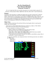
Ten-Tec has produced this document as a starting point for software developers undertaking the development of a
PC based Orion (Model 565) Interface program. The Ten-Tec Orion DSP HF transceiver is a product that is defined
more by firmware than hardware. As such, it is subject to change based on customer needs. The information presented
here is based on version x.xx of the Orion firmware. It is advisable to check for a more recent update at the Ten-Tec
firmware update site, www.rfsquared.com.
Conventions used in this manual
Numeric Types:
0x0A, 0Ah Hexadecimal Numbers.
10 Decimal Number.
‘A’ ASCII character code.
example: ASCII ‘A’ is 0x41.
BCD Binary Coded Decimal format
example: decimal 25 is 0x25 in BCD format
Information contained in this document applies to firmware version 1.367 and later.

Orion Programmer’s Reference Guide 5
Rev 1.2 Orion Firmware Updates at www.rfsquared.com
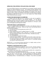
Interface Settings
The RS-232 serial interface on the Orion is controlled by a Uart Peripheral of the DragonBall processor located
on the Logic/DSP board. The interface parameters are fixed at 57,600 baud, No Parity, 8 Data bits, 1 Stop bit. The
UART uses hardware handshaking to control the data flow between the PC and the radio. The host PC should be set to
use RTS/CTS signalling.
ORION
COMPUTER
The diagram below shows the wiring and associated signals for a 9 pin to 9 pin
serial cable required to connect the Orion transceiver to a standard PC. If you pur-
chase a premade serial cable it should be a straight through cable.
Computer Pin Orion
CD. 1 N.C.
RXD 2 Serial Data Out
TXD 3 Serial Data In
DTR. 4 N.C.
GND 5 GND
DSR. 6 N.C.
RTS (out) 7 RTS (in)
CTS (in) 8 CTS (out)
RI. 9 N.C.

Orion Programmer’s Reference Guide
6Rev 1.2
Feedback? Comments? [email protected].
The ORION Command Set
The Orion command set is similar to the command sets for the RX-320 & RX-350 receivers and Pegasus/Jupiter
transceivers.
The command set is extensive and every effort has been made to keep the individual commands as simple as possible.
Although the ORION interface operates at 57,600 baud short commands are used to keep the processing overhead
to a minimum.
In general an ORION instruction is a two or three character command which may be followed by data and then
terminated by a carriage return <cr>. The ORION operates with plain-text data unless otherwise noted. This
eliminates the need to provide special pre-formatting to the data before sending it to the radio.
The ORION interface requires that data be in a format compatible with each command. Programmers should ensure
that the supplied data is correct. Where a command is unrecognized or data is invalid the radio will send back a
response consisting of the letters ‘Z!’ followed by the first 2 characters of the command string that caused the error
and finally, a carriage return <cr>. Command characters are case sensitive! In general, the query are identical to the
set command except the command is prefixed with a ‘?’ character.
Because the ORION was built to be reprogrammed in-system the command set presented here is subject to change
or enhancement. We will make every effort to make the system backward compatible with existing documented
commands whenever possible. However, the ORION is an HF TRASNCEIVER PLATFORM that could host a
variety of radio services. Persons or companies developing control software for the ORION should not assume that
the radio is operating original factory firmware but rather should always query the radio’s firmware revision to ensure
compatibility.
format: ‘X’ ‘X’ <cr>
where: ‘X’= is the ASCII ‘X’ character (0x58)
<cr> = ASCII carriage return (0x0D)
response: “ ORION START”
Restart and Notify
This command will cause the radio to do a software restart. Upon start-up the radio will issue the start message
“ORION START” indicating that it is initialized and ready to accept commands. Sending this command to the ORION
will cause the DSP firmware to reinitalize and generate the “ORION START” message. This command can be used to
determine that a Ten-Tec Flash Based radio is attached.

Orion Programmer’s Reference Guide 7
Rev 1.2 Orion Firmware Updates at www.rfsquared.com
Receiver Modes
The ORION supports AM,FM,LSB,USB,UCW,LCW & FSK modes.
Setting: *RMM<mode_code><cr> for main receiver.
*RSM<mode_code><cr> for sub receiver.
<mode_code> = Main receiver Mode
ASCII ‘0’ (0x30) for USB mode
ASCII ‘1’ (0x31) for LSB mode
ASCII ‘2’ (0x32) for UCW mode
ASCII ‘3’ (0x33) for LCW mode
ASCII ‘4’ (0x34) for AM mode
ASCII ‘5’ (0x33) for FM mode
ASCII ‘6’ (0x34) for FSK mode
<cr> = ASCII carriage return (0x0D) character.
examples:
*RMM1<cr> Sets Main Receiver to LSB mode.
*RMM2<cr> Sets Main Receiver to UCW mode.
*RSM4<cr> Sets Sub Receiver to AM mode.
*RSM5<cr> Sets Sub Receiver to FM mode.
Query: ?RMM<cr> for main receiver.
?RSM<cr> for sub receiver.
Radio will respond with @RMM<mode code><cr> for main receiver.
and @RSM<mode code><cr> for sub receiver.
sample responses:
@RMM2<cr> Indicates main receiver is in UCW mode.
@RSM0<cr> Indicates sub receiver in USB mode.

Orion Programmer’s Reference Guide
8Rev 1.2
Feedback? Comments? [email protected].
Audio Level Controls
Setting the audio volume of the receivers.
Setting: *UM<value><cr> for main receiver.
*US<value><cr> for sub receiver.
*UB<value><cr> for both receivers.
<value>= volume setting. range 0 (off) to 255 (maximum volume setting).
<cr>=ASCII carriage return (0x0D)
examples:
*UM125<cr> sets main receiver volume to 125.
*US90<cr> sets sub receiver volume to 90.
*UB200<cr> sets both the main receiver volume and sub receiver volume set to 200.
Query: ?UM<cr> for main receiver
?US<cr> for sub receiver
sample responses:
@UM50<cr> Indicates main volume at 50.
@US0<cr> Indicates sub audio at 0.
@UM163S255<cr>
Response from Both Query inicates both
volume settings.
The ‘U’ command is used to set the volume of each receiver and select how the audio is routed the speaker and head-
phones. As with other commands, the data fields are unformatted text strings.

Orion Programmer’s Reference Guide 9
Rev 1.2 Orion Firmware Updates at www.rfsquared.com
A variation of the ‘U’ command provides for control of Binaural Receive Mode.
Setting: *UR<s><cr>
<s>= Left headphone output selection.
‘M’ for Main Receiver.
‘S’ for Sub Receiver
‘O’ for Off.
<cr>=ASCII carriage return (0x0D)
examples:
*URM<cr> Sets Binaural Receive mode for the main receiver.
*URS<cr> Sets Binaural Receive mode for the sub receiver.
*URO<cr> Turns OFF Binaural Receive mode.
Query: ?UR<cr>
sample responses:
@URO<cr> Indicates Binaural Receive Mode is OFF
@URM<cr> Indicates Binaural Receive Mode enabled for the main receiver.
Binaural Receive Control

Orion Programmer’s Reference Guide
10 Rev 1.2
Feedback? Comments? [email protected].
Routing Speaker and Headphone Outputs
A variation of the ‘U’ command provides for control of receiver audio routing. This form differs from the volume setting
.
Setting: *UC<lv><rv<sv><cr>
<lv>= Left headphone output selection.
‘M’ for Main Receiver.
‘S’ for Sub Receiver
‘B’ for Both Receivers.
<rv>= Right headphone output selection.
‘M’ for Main Receiver.
‘S’ for Sub Receiver
‘B’ for Both Receivers.
<sv>= Speaker output selection.
‘M’ for Main Receiver.
‘S’ for Sub Receiver
‘B’ for Both Receivers.
<cr>=ASCII carriage return (0x0D)
examples:
*UCBBB<cr> Sets audio of both receivers to the the Left, Right & Speaker outputs.
*UCMSB<cr> Routes Main Receiver to the Left headphone and the speaker and
routes Sub Receiver to the Right Headphone and the speaker.
Query: ?UC<cr>
sample responses:
@UCBBB<cr> Indicates Left, Right and Speaker will contain audio
from BOTH receivers.
@UCMSB<cr> Indicates
Left headphone=main receiver audio.
Right headphone=sub receiver audio.
Speaker = Audio from both receivers.
Speaker & Headphone Settings

Orion Programmer’s Reference Guide 11
Rev 1.2 Orion Firmware Updates at www.rfsquared.com
Receive Filter
The ORION does not contain a predefined DSP filter set. When a filter is selected the DSP creates the requested filter
on-the-fly. Filters can be programmed between 100 and 6000 Hz to a resolution of 1 Hz.
Setting: *RMF<bw> <cr> for main receiver
*RSF<bw> <cr> for sub receiver
<bm>=receiver bandwidth 100hz to 6000 hz.
<cr>= carriage return.
examples:
*RMF1200<cr>
Sets main receiver fillter bandwidth to 1200 Hz.
*RSF6000<cr>
Sets sub receiver fillter bandwidth to 6 kHz.
Query: ?RMF<cr> for main receiver.
?RSF<cr> for sub receiver.
sample responses:
@RMF2400<cr>
indicates the main receiver filter is 2400 Hz wide.
@RSF400<cr>
indicates the sub receiver filter is 400 Hz wide.

Orion Programmer’s Reference Guide
12 Rev 1.2
Feedback? Comments? [email protected].
Antenna Selections
The Orion contains two transceiver antenna ports and an auxillary receiver port.
Setting: *KA[ant1][ant2][rxant] <cr>
[ant1] = Antenna 1 Selection
‘S’ for rx/tx.
‘M’ for main receiver.
‘B’ for both.
‘N’ for not assigned
[ant2] = Antenna 2 Selection
‘S’ for rx/tx.
‘M’ for main receiver.
‘B’ for both.
‘N’ for not assigned
[rxant] = Auxillary Receive Antenna Selection
‘S’ for rx/tx.
‘M’ for main receiver.
‘B’ for both.
‘N‘ for not assigned.
<cr> = ASCII carriage return (0x0D)
NOTE: Main rx/tx must be assigned to either ANT1 or ANT2.
examples: * KAMMM<cr>
Sets Antenna 1 to the Tx, Sub Rx and sets aux rx for the main receiver.
* KAMSN<cr>
Sets Antenna 1 to the Main Rx and Tx, Sub Rx on Antenna 2. Aux antenna not
selected.
* KABNN<cr>
Sets Antenna 1 to the Main Rx and Tx and Sub Rx. Antenna 2 and Aux
antenna not selected.
Query: ?KA<cr>
sample responses:
@KAMMM<cr>
Indicates Antenna 1 to the Tx, Sub Rx and sets aux rx for the main receiver.
@KAMSN<cr>
Indicates Ant 1 to the Main Rx and Tx, Sub Rx on Ant 2. Aux antenna not selected.

Orion Programmer’s Reference Guide 13
Rev 1.2 Orion Firmware Updates at www.rfsquared.com
Frequency Tuning
Extensive tuning cababilities are built into the Orion command set. Besides independent of the A and B VFOs, the radio
may be tuned in ABSOLUTE, OFFSET or INCREMENTAL modes using plain-text character strings. In addition,
compatibility with other Ten-Tec transceivers is maintained through a 4-byte binary frequency tuning mode.
ABSOLUTE:
The abosolute tuning mode provides a means to tune the vfo directly to the desired frequency. The command prefix is
*AF for VFOA or *BF for VFOB. The target frequency may be specified in Hz or MHz.
example1: *AF14.250<cr> tunes VFOA to 14.250
example2: *BF10.113<cr> tuned VFOB to 10.113
example3: *AF10.113<cr> tuned VFOA to 10.113
OFFSET:
The offset tuning mode allows a VFO to be adjusted by a given amount. The command prefix is *A+ or *A- for VFOA
and *B+ or *B- for VFOB. The offset amount is specified in Hz.
example1: if VFOA is 10.150 MHz then *A-1000<cr> would change VFOA to 10.149 MHz
example2: if VFOB is 3.980000 MHz then *A+500<cr> would change VFOB to 3.980500 MHz
example3: if VFOB is 7.100000 MHz then *A+1<cr> would change VFOB to 7.100001 MHz
NOTE!! Changes smaller than current step size will be ignored.
INCREMENTAL:
The incremental tuning mode allows a vfo to be stepped up or down in increments of the selected tuning step. The
comamnd prefix is *AS+ or *AS- for VFOA and *BS+ or *BS- for VFOB. The increment is specified in steps and
has a range of +/- 32767 steps.
example1: *AS+10 causes VFOA to move up in frequency by 10 tuning steps
example2: *BS+10 causes VFOB to move up in frequency by 10 tuning steps
example3: *AS-22 causes VFOA to move down in frequency by 22 tuning steps

Orion Programmer’s Reference Guide
14 Rev 1.2
Feedback? Comments? [email protected].
format: ‘*’ [‘A’ or ‘B’] b3 b2 b1 b0 <cr>
where: ‘*’ = the ASCII ‘*’ symbol (0x2a).
A = the ASCII ‘A’ character (0x41).
B = the ASCII ‘B’ character (0x42).
b3-b0 =
Frequency in Hz as a 4 byte binary number. The most sugnificant byte is b3.
The least significant byte is b0.
example1: *A <0x00> <0xe4> <0xe1> <0xc0> <0x0d> would set the A vfo to
15,000,000 Hz or 15 MHz.
example2: *B <0x00> <0x5b> <0x2b> <0xd8> <0x0d> would set the B vfo to
5,975,000 Hz or 5.975 MHz.
default: none
4-Byte Binary Format
A 4-byte binary format may also be used to set the VFO frequency. This is provided to be backward compatible with
other Ten-Tec radios.
QUERY: ?AF<cr> for ASCII frequency of VFOA.
?BF<cr> for ASCII frequency of VFOB.
?A<cr> for VFOA contents in 4-byte format.
?B<cr> for VFOB contents in 4-byte format.
response examples:
@AF14200000<cr>
Indicates VFOA set to 14.2 MHz.
@A<0x00><0x6A><0xCF><0xC0> <cr>
Indictes VFOA set to 7 MHz in 4-byte format.

Orion Programmer’s Reference Guide 15
Rev 1.2 Orion Firmware Updates at www.rfsquared.com
Passband Tuning (PBT)
The passband tuning range of the ORION is +/- 8000 Hz. Setting the PBT to 0 will turn the passband tuning control
OFF. The data format is an ASCII number which represents the PBT value in Hz.
Setting: *RMP<pbt_val> <cr> for main receiver
*RSP<pbt_val><cr> for sub receiver.
<pbt_val>=Passband offset in Hz. Range +/- 8000 Hz.
<cr> = ASCII carriage return (0x0D) character.
examples:
*RMP150<cr>
would set the Main Receiver’s PBT to +150 Hz.
*RMP-200<cr>
would set the Main Receiver’s PBT to -200 Hz.
*RSP+200<cr>
would set the Sub Receiver’s PBT to +200 Hz.
Query: ?RMP<cr> for main receiver.
?RSP<cr> for sub receiver.
sample responses:
@RMP-200<cr>
Indicates main receiver PBT value is set to -200 Hz.
@RSP0<cr>
Indicates sub receiver PBT is set to 0.

Orion Programmer’s Reference Guide
16 Rev 1.2
Feedback? Comments? [email protected].
VFO Lock/Unlock
Locking a VFO prevents unintended frequency tuning. Each VFO can Locked/Unlocked independently.
Setting: *AL<cr> to Lock VFOA.
*AU<cr> to Unlock VFOA.
*BL<cr> to Lock VFOB.
*BU<cr> to Unlock VFOB.
<cr>=ASCII carriage return (0x0D)
examples: *AL<cr> Locks VFO-A.
*BL<cr> Locks VFO-B.
*AU<cr> Unlocks VFO-A.
Query: ?AU or ?AL for VFOA.
?BU or ?BL for VFOB.
samples response:
@AL<cr> indicates VFOA is locked.
@AU<cr> indicates VFOA is unlocked.

Orion Programmer’s Reference Guide 17
Rev 1.2 Orion Firmware Updates at www.rfsquared.com
Setting: *RMA<agc_mode> <cr> for main receiver.
*RSA<agc_mode> <cr> for sub receiver.
<agc_mode> = Receiver AGC mode
O = off
F = fast
M = medium
S = slow
P = program
examples: *RMAF<cr>
sets main receiver AGC operation to FAST.
*RSAS<cr>
sets sub receiver AGC operation to SLOW.
*RMAO<cr>
sets main receiver agc to OFF.
Query: ?RMA for main receiver.
?RSA for sub receiver.
sample responses:
@RMAO<cr>
Indicates main receiver AGC is OFF.
@RSAF<cr>
Indicates sub receiver is set to FAST AGC.
AGC Mode Control

Orion Programmer’s Reference Guide
18 Rev 1.2
Feedback? Comments? [email protected].
RF Gain Control
The relative RF gain can be controlled over a range of 0-100. A setting of 0 represents full RF gain whereas a setting of
100 represents the maximum RF gain level. Because this control directly affects the RF hardware this will directly affect
S-Unit responses and Squelch settings.
Setting: *RMG<gain_value> <cr> for main receiver
*RSG<gain value><cr> for sub receiver.
<gain_value> = Receiver RF gain. Range 1-100.
<cr> = carriage return.
examples: *RMG100<cr>
Sets main receiver rf gain to 100.
*RSG50<cr>
Sets sub Receiver RF Gain to 50.
*RSG1<cr>
Sets Sub Receiver RF Gain to 1.
Query: ?RMG for main receiver.
?RSG for sub receiver.
sample responses:
@RMG100<cr>
indicates main receiver RF Gain setting at 100%.
@RSG50<cr>
indicates sub receiver RF Gain setting at 50%.

Orion Programmer’s Reference Guide 19
Rev 1.2 Orion Firmware Updates at www.rfsquared.com
RF Attenuator
Setting: *RMT[val] <cr> for main receiver.
*RST[val] <cr> for sub receiver.
[val]= For Attenuator
‘0’ (0x30) = OFF
‘1’ (0x31) = 6dB
‘2’ (0x32) = 12 dB
‘3’ (0x33) = 18dB
<cr> = ASCII carriage return (0x0D)
examples: *RMT0<cr>
sets the Main Receiver Attenuator OFF.
* RST2<cr>
sets the Sub Receiver Attenuator to 12 dB.
* RST0<cr>
sets the Sub Receiver Attenuator to OFF.
* RMT1<cr>
sets the Main Receiver Attenuator to 6 dB.
Query: ?RMT for main receiver.
?RST for sub reciever.
sample responses:
@RMT1<cr>
indicates main receiver attenuator set to 6 dB.
@RST0<cr>
indicates sub receiver attenuator set to OFF.

Orion Programmer’s Reference Guide
20 Rev 1.2
Feedback? Comments? [email protected].
VFO Assignments
The Orion contains two independent VFOs coupled to a ham-bands-only transceiver and general-coverage sub-
receiver. Before the main receiver, transmitter or sub-receiver can be tuned it must be associated with one of the two
available vfos. The VFO assignment command allows for arranging the receiver/transmitter/VFO combinations. In
general this is a simple process but the contents of a particular VFO may prevent the assignment. When a VFO contains
a frequency that is out-of-range for the intended receiver/transmitter ALL the assigments are rejected and the Orion will
respond with an error string indicating the particular VFO that is out-of-range.
format: *KV[mrx][srx][mtx] <cr>
[mrx] = VFO associated with the main receiver.
‘A’ for VFOA.
‘B’ for VFOB.
[srx] = VFO associated with the sub receiver.
‘A’ for VFOA.
‘B’ for VFOB.
‘N ‘ for no assignment.
[mtx] = VFO associated with the transmitter.
‘A’ for VFOA.
‘B’ for VFOB.
‘N‘ for no assignment.
<cr> = ASCII carriage return (0x0D)
response: If not possible to make the assignements the radio will respond with
Z!A<cr> indicating VFOA out-of-range
or
Z!B<cr> indicating VFOB out-of-range
or
Z!AB<cr> indicating BOTH out-of-range
examples: * KVAAA<cr>
Set Main Rx, Sub Rx and Tx to VFOA.
* KVABA<cr>
Sets Main Rx and TX to VFOA and Sub Rx to VFOB.
* KVA <cr> Set Main Rx to VFOA and removes association with Sub receiver
and Transmitter.
Query: ?KV<cr>
sample response:
@KVABA<cr>
indicates main receiver on VFOA, sub receiver on VFOB and main transmitter on
VFOA.
Page is loading ...
Page is loading ...
Page is loading ...
Page is loading ...
Page is loading ...
Page is loading ...
Page is loading ...
Page is loading ...
Page is loading ...
Page is loading ...
Page is loading ...
Page is loading ...
Page is loading ...
Page is loading ...
Page is loading ...
Page is loading ...
Page is loading ...
Page is loading ...
Page is loading ...
Page is loading ...
Page is loading ...
Page is loading ...
-
 1
1
-
 2
2
-
 3
3
-
 4
4
-
 5
5
-
 6
6
-
 7
7
-
 8
8
-
 9
9
-
 10
10
-
 11
11
-
 12
12
-
 13
13
-
 14
14
-
 15
15
-
 16
16
-
 17
17
-
 18
18
-
 19
19
-
 20
20
-
 21
21
-
 22
22
-
 23
23
-
 24
24
-
 25
25
-
 26
26
-
 27
27
-
 28
28
-
 29
29
-
 30
30
-
 31
31
-
 32
32
-
 33
33
-
 34
34
-
 35
35
-
 36
36
-
 37
37
-
 38
38
-
 39
39
-
 40
40
-
 41
41
-
 42
42


Ask a question and I''ll find the answer in the document
Finding information in a document is now easier with AI
Related papers
-
 Ten-Tec 566 Orion II User manual
-
 Ten-Tec 516 Argonaut V Reference guide
-
 Ten-Tec 565 Orion User manual
-
 Ten-Tec 538 Jupiter Operating instructions
-
 Ten-Tec 588AT OMNI-VII Tx User manual
-
 Ten-Tec 565 Orion User manual
-
 Ten-Tec 564 User manual
-
 Ten-Tec 253 User manual
-
 Ten-Tec 420 User manual
-
 Ten-Tec 538 Jupiter User manual


Other documents
-
YAESU FT-897 Operating instructions
-
YAESU FT-817 - Operating instructions
-
Alinco DX-77 User manual
-
YAESU FT-2000 - MENU MODE LIST Operating instructions
-
-
Yaesu Musen FT-817 - User manual
-
ICOM IC-736 738 Owner's manual
-
-
YAESU FT-857 series Operating instructions
-
 Xiegu X5105 User manual
