Page is loading ...

Wiring for Robotiq Adaptive Gripper S model with M12/M8
The following procedure is for Robotiq Adaptive Gripper S model with M12 power connector and M8
communication connectors. This document replaces section 3.4 and 3.4.1 of the Adaptive Gripper S Model
Insctruction Manual. All other sections of the Insctruction Manual for Firmware 3 still apply.
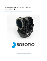
3.4 Wiring
Two connections are needed for the Adaptive Gripper S Model, one for power and one for
communication. On the Gripper, both are located on the Connection Panel shown in Figure 3.4.1.
Figure 3.4.1 - Power and communication receptacles
Warning
Use proper cabling management. Be sure to have enough forgiveness in the cabling to allow
movement of the Gripper along all axes without pulling out the connectors.
3.4.1 Power connection
Here is the way the Gripper should be connected to a power source (Figure 3.4.1.1).
Communication
Receptacle Power
Receptacle

24 V
DC
Robotiq
Adaptative
Gripper S model
Fuse 4A
+
-
Figure 3.4.1.1 - Power connection diagram of the Adaptive Gripper S
Caution
The 4A fuse is external to the Gripper. It is not provided by Robotiq and the user is responsible for proper
installation.
The pin-out of the power connectors is detailed in Figure 3.4.1.2.
M8 3 POLE MALE AND FEMALE
GND
SUPPLY +
SUPPLY -
GREEN/YELLOW
RED
BLACK
M12 3 Pole Female Connector
1
3
2
21
1.
2.
3.
3
M12 3 Pole Male Connector
MALE FEMALE
BROWN
BLUE
BLACK
Figure 3.4.1.2 - Gripper Power Inlet and Power Connector.
The Adaptive Gripper S Model should be supplied with cables that have the following specications:
Approximate length of 5 meters #22 AWG TEW cable, 300V or 600V.
3 conductors, 2 for the supply and one for the protective ground.
Shielding, depending on the application. Shield must be grounded in robot controller.

3.4.2 Communication connection
The same communication cable and connectors are used for all the protocols but each protocol has its own pin-out.
Warning
Be sure to use the appropriate cables and pin-outs for your communication protocol as any other setup may damage the
gripper.
DeviceNet communication protocol
Figure 3.5 shows the pin-out for the DeviceNet communication protocol.
The following table summarizes the communication protocols available for the Gripper.
Note that only one protocol option is available in a given Gripper unit. The Gripper that you have was congured
before shipment with only one of the following protocols.
Warning
Be sure to use the appropriate cables and pin-outs for your communication protocol as any other
setup may damage the Gripper.
Family Protocol
Real-Time-Ethernet
EtherNet/IP
Modbus TCP/IP
EtherCAT
Fieldbus DeviceNet
Serial Modbus RTU
Figure 3.5 – DeviceNet communication pin-out.
Caution
There is no terminating resistor mounted in the Gripper.
The shielding of the cable must be grounded in the robot controller.
M8 5 POLE MALE AND FEMALE
CAN_H
DN -
SHIELD
WHITE
BLACK
GRAY
1.
2.
3.
4.
5.
1
2
3
4
5
1
5
24
3
M8 5 Pole Male Receptacle M8 5 Pole Female Connector
DN +
CAN_L
RED
BLUE

The DeviceNet communication and the Adaptive Gripper use 24 V supply. Robotiq suggests to separate power
supplies as shown in Figure 3.6.
Figure 3.6 – Power connection diagram of the Adaptive Gripper using DeviceNet Fieldbus.
Factory settings for DeviceNet protocol:
Robotiq
Adaptative
Gripper
Fuse 4A
+
-
DeviceNet
Fieldbus
24V
DC
Fuse 4A
24V
DC
+
-
DeviceNet
Cable
Info Decimal value (base 10) Hexadecimal value (base 16)
Vendor ID : 283 0x0000011B
Product Code : 35 0x00000023
Serial Number : 00x00000000
Product Type : 12 0x0000000C
Major Revision : 1
Minor Revision : 1
Product Name : AG-DNS
IDENTIFICATION SETTINGS
BUS SETTING
MAC ID : 11
Baud Rate : 250 kBaud
DATA SETTINGS
Prod. Data Length : 12
Cons. Data Length : 12

Real-time Ethernet communication protocol
Real-time Ethernet communication includes Ethernet/IP, EtherCAT and Modbus TCP/IP protocols.
See the Real-Time Ethernet pin-out diagram below (Figure 3.7).
Figure 3.7 – Real-Time Ethernet communication pin-out.
Caution
The crossover on the RX/TX signals is made inside the Gripper.
M8 5 POLE MALE AND FEMALE
TXP
RXN
-
WHITE
BLACK
GRAY
1.
2.
3.
4.
5.
1
2
3
4
5
1
5
24
3
M8 5 Pole Male Receptacle M8 5 Pole Female Connector
RXP
TXN
RED
BLUE
Factory settings for Ethernet protocols:
EtherCat EtherNet/IP Modbus TCP/IP
IDENTIFICATION SETTINGS
Vendor ID : 0xE0000044 Vendor ID : 0x0000011B N / A
Product Code : 0x0000000B Product Code : 0x0000010D
Serial Number : 0x00000000 Product Type : 0x0000000C
Revision Number : 0x00000000 Major Revision : 1
Minor Revision : 1
Device Name : AG-EIS

EtherCat EtherNet/IP Modbus TCP/IP
BUS SETTING
N / A (see info note) IP Address : 192.168.1.11 IP Address : 192.168.1.11
Netmask : 255.255.255.0 Netmask : 255.255.255.0
Gateway : Disabled Gateway : Disabled
BootP : Disabled BootP : Disabled
DHCP : Disabled DHCP : Disabled
100Mbit : Enabled 100Mbit always on
Full Duplex: Enabled Full Duplex always on
Auto-neg : Enabled Auto-neg always on
Assembly Instance (input) : 101
Assembly Instance (output) : 100
Conguraton Instance : 1
Connection Type : Run/Idle Header
EtherCat EtherNet/IP Modbus TCP/IP
DATA SETTINGS
Input Data Bytes : 12 Prod. Data Length : 16 N / A
Output Data Bytes : 12 Cons. Data Length : 16 N / A
Info
Ethercat protocol uses inherent dynamic addressing thus bus settings cannot be customized.
Serial communication protocol
Figure 3.8 shows the pin-out of the communication connectors when used in serial mode.

Figure 3.8 – Serial communication pin-out.
M8 5 POLE MALE AND FEMALE
GND
TX
-
WHITE
BLACK
GRAY
1.
2.
3.
4.
5.
1
2
3
4
5
1
5
24
3
M8 5 Pole Male Receptacle M8 5 Pole Female Connector
RX
-
RED
BLUE
Factory settings for Modbus RTU protocols:
INDENTIFICATION SETTINGS
Device: 9
BUS SETTINGS
See section 4.9.1 of the Adaptive Gripper S Model
Instruction Manual
DATA SETTINGS
Number of Register: 5000
/