Page is loading ...

—
ABB MEASUREMENT & ANALYTICS | OPERATING INSTRUCTION
EBS852 / EBS862
Electronic unit for rack mount installation (Contrac)
—
ABB Limited
Measurement & Analytics
Howard Road, St. Neots
Cambridgeshire, PE19 8EU
UK
Tel: +44 (0)870 600 6122
Fax: +44 (0)1480 213 339
Email: [email protected]m
ABB Automation Products GmbH
Measurement & Analytics
Schillerstr. 72
32425 Minden
Germany
Tel: +49 571 830-0
Fax: +49 571 830-1806
abb.com/actuators
ABB Inc.
Measurement & Analytics
125 E. County Line Road
Warminster, PA 18974
USA
Tel: +1 215 674 6000
Fax: +1 215 674 7183
For the control of Contrac control
actuators in potentially explosive
atmospheres
OI/EBS852/EBS862/EX-EN Rev. B 10.2018
—
EBS852
EBS862
Introduction
The electronic unit builds the interface between
the actuator and the control system.
During continuous positioning, the electronic unit
varies the motor torque continuously until the
actuator force and the control valve force are
balanced.
High response sensitivity and high positioning
accuracy with short positioning time ensure an
excellent control quality and a long actuator life.
Additional Information
Additional documentation on EBS852 / EBS862 is
available for download free of charge at
www.abb.com/actuators.
Alternatively simply scan this code:
—
We reserve the right to make technical changes or modify the contents of this document
without prior notice. With regard to purchase orders, the agreed particulars shall prevail.
ABB does not accept any responsibility whatsoever for potential errors or possible lack of
information in this document.
We reserve all rights in this document and in the subject matter and illustrations contained
therein. Any reproduction, disclosure to third parties or utilization of its contents – in whole
or in parts – is forbidden without prior written consent of ABB.
Copyright© 2018 ABB
All rights reserved 3KXE181010R4201

2 EBS852 / EBS862 ELECTRONIC UNIT | OI/EBS852/EBS862/EX-EN REV. B
Table of contents
Change from one to tw o columns
1 Safety .......................................................................... 3
General information and instructions .................................. 3
Warnings .................................................................................... 3
Intended use ............................................................................. 4
Improper use ............................................................................. 4
Notes on data safety ............................................................... 4
Warranty provisions ................................................................. 4
Manufacturer’s address .......................................................... 4
2 Use in potentially explosive atmospheres ............. 5
Thermal motor monitoring .................................................... 5
Cable harness for the connection of the actuator to the
electronic unit ........................................................................... 5
Specification ........................................................................ 6
Overview .................................................................................... 8
3 Design and function .................................................. 9
Design ........................................................................................ 9
EBS852 ................................................................................... 9
EBS862 .................................................................................. 9
Principle of operation ............................................................ 10
Device designs ........................................................................ 11
4 Product identification ............................................ 12
Scope of delivery .................................................................... 12
Delivery status ........................................................................ 13
5 Transport and storage ............................................ 13
Inspection ................................................................................ 13
Transporting the device ........................................................ 13
Safety instructions ............................................................ 13
Returning devices ................................................................... 13
Storing the device .................................................................. 13
6 Installation ............................................................... 14
Mounting ................................................................................. 14
EBS852 ................................................................................. 14
EBS862 ................................................................................ 15
Assembly and cable routing in the mounting rack...... 15
Dimensions .............................................................................. 16
Electronic unit EBS852 (Contrac) ................................... 16
Electronic unit EBS862 (Contrac) ................................... 17
7 Electrical connections ............................................. 19
Safety instructions ................................................................. 19
General ..................................................................................... 19
Conductor cross-section on control actuator .................. 19
Conductor cross-section on electronic unit ...................... 20
Cable glands ....................................................................... 20
Selection of suited connection cables........................... 20
Potential equalization ........................................................... 21
Actuator assignment and maximum cable lengths ......... 22
Connection examples ............................................................ 24
Electrical data for inputs and outputs ............................... 26
Connection on the device ................................................ 28
8 Commissioning and operation .............................. 30
General information .............................................................. 30
Engineering Software ECOM688 and ECOM700 ......... 30
Checks prior to commissioning .......................................... 30
Before powering up the power supply .......................... 30
After powering up the power supply ............................ 30
Commissioning and service field ......................................... 31
Meaning of the LED indicators ....................................... 32
Hardware settings ................................................................. 33
Basic Setup ............................................................................. 33
Manual (MAN)- and Automatic Operation (AUT) ............. 34
9 Diagnosis / error messages ................................... 35
Definition – Alarms and Errors ............................................ 35
Alarm Diagram ....................................................................... 35
Error Diagram ......................................................................... 36
Hardware Errors ..................................................................... 37
10 Maintenance ............................................................ 38
Electronic unit ........................................................................ 38
Control actuator .................................................................... 38
11 Repair ....................................................................... 38
Returning devices .................................................................. 38
Fuses ........................................................................................ 39
12 Recycling and disposal ........................................... 40
Notice on RoHS II-Directive 2011/65/EU ........................... 40
13 Approvals and certifications ................................. 40
14 Additional documents ............................................ 40
15 Appendix ................................................................... 41
Return form ............................................................................. 41

EBS852 / EBS862 ELECTRONIC UNIT | OI/EBS852/EBS862/EX-EN REV. B 3
Change from one to tw o columns
1 Safety
General information and instructions
These instructions are an important part of the product and
must be retained for future reference.
Installation, commissioning, and maintenance of the product
may only be performed by trained specialist personnel who have
been authorized by the plant operator accordingly. The specialist
personnel must have read and understood the manual and must
comply with its instructions.
For additional information or if specific problems occur that are
not discussed in these instructions, contact the manufacturer.
The content of these instructions is neither part of nor an
amendment to any previous or existing agreement, promise or
legal relationship.
Modifications and repairs to the product may only be performed
if expressly permitted by these instructions.
Information and symbols on the product must be observed.
These may not be removed and must be fully legible at all times.
The operating company must strictly observe the applicable
national regulations relating to the installation, function testing,
repair and maintenance of electrical products.
Warnings
The warnings in these instructions are structured as follows:
DANGER
The signal word ‘DANGER’ indicates an imminent danger.
Failure to observe this information will result in death or
severe injury.
WARNING
The signal word ‘WARNING’ indicates an imminent danger.
Failure to observe this information may result in death or
severe injury.
CAUTION
The signal word ‘CAUTION’ indicates an imminent danger.
Failure to observe this information may result in minor or
moderate injury.
NOTICE
The signal word
‘
NOTIC
E
’
indicates possible material damage.
Note
‘Note’ indicates useful or important information about the
product.

4 EBS852 / EBS862 ELECTRONIC UNIT | OI/EBS852/EBS862/EX-EN REV. B
… 1 Safety
Intended use
The electronic units of type EBS852 / EBS862 interconnected as
illustrated in this operating instruction are used exclusively to
control the RHDE... or RSDE... series control actuators.
The electronic unit must only be installed or commissioned
outside of potentially explosive atmospheres.
Using these actuators for any other purpose will introduce a risk
of personal injury and can also damage or impair the device's
operational reliability.
Improper use
The following are considered to be instances of improper use of
the device:
• For use as a climbing aid, for example for mounting
purposes.
• For use as a bracket for external loads, for example as a
support for piping, etc.
• Material application, for example by painting over the
housing, name plate or welding/soldering on parts.
• Material removal, for example by spot drilling the
housing.
Notes on data safety
This product is designed to be connected to and to
communicate information and data via a network interface.
It is operator’s sole responsibility to provide and continuously
ensure a secure connection between the product and your
network or any other network (as the case may be).
Operator shall establish and maintain any appropriate measures
(such as but not limited to the installation of firewalls,
application of authentication measures, encryption of data,
installation of anti-virus programs, etc.) to protect the product,
the network, its system and the interface against any kind of
security breaches, unauthorized access, interference, intrusion,
leakage and / or theft of data or information.
ABB Automation Products GmbH and its affiliates are not liable
for damages and / or losses related to such security breaches,
any unauthorized access, interference, intrusion, leakage and /
or theft of data or information.
Warranty provisions
Using the device in a manner that does not fall within the scope
of its intended use, disregarding this manual, using
underqualified personnel, or making unauthorized alterations
releases the manufacturer from liability for any resulting
damage. This renders the manufacturer's warranty null and void.
Manufacturer’s address
ABB Automation Products GmbH
Measurement & Analytics
Schillerstr. 72
32425 Minden
Germany
Tel: +49 571 830-0
Fax: +49 571 830-1806
Customer service center
Tel: +49 180 5 222 580
Email: [email protected]

EBS852 / EBS862 ELECTRONIC UNIT | OI/EBS852/EBS862/EX-EN REV. B 5
2 Use in potentially explosive atmospheres
DANGER
Explosion hazard due to improper installation!
An explosion hazard is present when installing the electronic
unit in potentially explosive atmospheres.
The electronic unit must only be installed and operated
outside of potentially explosive atmospheres.
Before the commissioning of the electronic unit, observe the
following points:
• The electronic unit must not be installed or commissioned in
an Ex area.
• Check whether the actuator is connected to the right
electronic unit, see section Electrical data for inputs and
outputs on page 26.
• Check whether the associated electronic unit has been
configured using the correct actuator parameters. To do this,
check the relevant information on the name plate of the
actuator and the electronic unit with respect to actuator
type, ambient temperature range of actuator, and NL
number, if applicable.
• On delivery, the positioning time-out function of the
electronic unit associated with the actuator is activated.
Deactivating this setting is not permitted.
• Rapid traverse mode is not allowed to be used on Ex
actuators. Therefore, it is not possible to select it via the user
interface.
• Activating the breakaway function is not permitted.
• Activating the ‘Position dependent switch-off’ function with
2 × torque/force is not permitted.
• The Contrac electronic unit must be upstream of the motor
temperature monitoring unit SD241-B or a similar, certified
tripping unit.
Thermal motor monitoring
In Contrac control actuators for use in potentially explosive
atmospheres, additional independent monitoring of motor
temperature is required.
Monitoring can be performed using the ABB SD241-B monitoring
unit or a comparable certified tripping unit for thermistor
temperature sensors.
The motor temperature monitoring unit interrupts the power
supply as soon as the motor temperature up-scales the
permissible limit value.
Cable harness for the connection of the
actuator to the electronic unit
Installation information on the cable harness for actuators in
Ex design
The electrical connection between the Contrac electronic unit
and the Contrac actuator can be established using the cable set
(order code 695). The cable harness is not part of the Ex
prototype test certificate and must therefore be tested for
safety-relevant functionality within the complete installation by
the installer or operator.
If the specified cable harness does not meet all safety-relevant
requirements, the proper installation material must be used.
For the specified motor connection cable, the shielding must be
connected at both ends and connected with protective ground.
Change from two to one column

6 EBS852 / EBS862 ELECTRONIC UNIT | OI/EBS852/EBS862/EX-EN REV. B
… 2 Use in potentially explosive atmospheres
… Cable harness for the connection of the actuator to the electronic unit
Specification
Motor connection Motor temperature monitoring Signal terminal (option)
Wire conductor 8 × 1.5 2 × 1.5 8 × 0.5
Mat.-No. 9280271 9280272 9280183
Manufacturer Huber + Suhner Huber + Suhner Bröckskes (Helu-Kabel)
Type RX125 S2 B 8g1.5 mm2 BK RX125 S2 2×1.5 mm2 BK So-LTG-PUR-8 × 0.5
(HK-So-Li12YC11Y-OB-8 × 0.5)
Sheathing diameter 14.3 ±0.4 mm
(0.56 ±0.02 in)
8.0 ±0.4 mm
(0.31 ±0.02 in)
8.5 ±0.4 mm
(0.33 ±0.02 in)
Nominal voltage Uo / U
(Uo also applies to wire / shielding)
600 / 1000 V 600 / 1000 V 300 / 500 V
Wire / wire test voltage 3.5 kV 3.5 kV 1.2 kV
Temperature range Motor connection Motor temperature monitoring Signal terminal (option)
Moving −25 to 125 °C (−13 to 257 °F) −25 to 125 °C (−13 to 257 °F) −40 to 90 °C −40 to 194 °F)
Not moving −40 to 125 °C (−40 to 257 °F) −40 to 125 °C (−40 to 257 °F) −50 to 90 °C (−58 to 194 °F)
Protective earth GNYE
Environment UV-resistant and weather-proof UV-resistant and weather-proof UV-resistant and weather-proof
Motor connection Motor temperature monitoring Signal terminal (option)
Cable gland 13.5 to 18 / M25 × 1.5 Exe 4 to 8.5 / M20 × 1.5 Exe
Mat.-No. 9287589 9287588
Manufacturer Rabe-System-Technik Rabe-System-Technik
Type CMDEL-T ADE 1F
Article no. 00222574 00816674
Cable diameter 13.5 to 18 mm
(0.53 to 0.71 in)
4 to 8.5 mm
(0.16 to 0.33 in)
Material Brass, nickel-plated Brass, nickel-plated
Standard seal insert Neoprene Neoprene
O-ring Perbunan Neoprene
Temperature range −40 to 100 °C (−40 to 212 °F) −40 to 100 °C (−40 to 212 °F)
IP rating IP 68 - 10 bar (140.04 psi) IP 68 - 5 bar (72.52 psi)
Certificate LCIE 97 ATEX 6005 X / 01 LCIE 97 ATEX 6008 X / 03
Marking
II 2 G D
Ex e II / Ex tD
Ex II 2 G D, Exe II

EBS852 / EBS862 ELECTRONIC UNIT | OI/EBS852/EBS862/EX-EN REV. B 7
Option
Motor connection Motor temperature monitoring Signal terminal (option)
Manufacturer Pflitsch Pflitsch
Type blue globe ATEX blue globe ATEX
Diameter M25 × 1.5 KAD20-16/16-11 M20 × 1.5 KAD14-9/9-5
Article no. bg225 msex bg220 msex
Temperature range −40 to 115 °C (−40 to 239 °F) −40 to 115 °C (−40 to 239 °F)
IP rating IP 68 IP 68
Certificate PTB 06 ATEX 1036 X PTB 06 ATEX 1036 X
Marking II 2 G Ex e II II 2 D Ex tD A21 IP68
Note
If the specified cable harness does not meet all safety-relevant requirements, the proper installation material must be used.

8 EBS852 / EBS862 ELECTRONIC UNIT | OI/EBS852/EBS862/EX-EN REV. B
… 2 Use in potentially explosive atmospheres
Overview
Figure 1: Allocation of the Contrac components when using in potentially explosive atmospheres (example)
Change from one to tw o columns
Change from one to tw o columns

EBS852 / EBS862 ELECTRONIC UNIT | OI/EBS852/EBS862/EX-EN REV. B 9
3 Design and function
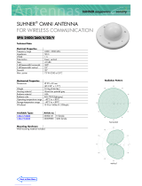
Design
EBS852
M10450
3
4
6
7
9
5
8
1
2
1 Commissioning and service field
2 Transformer
3 Strain relief
4 Ground terminal
5 Mains fuse
6 Terminals (power supply)
7 Terminals (motor cable)
8 Binary output fuses
9 Terminals (signals)
Figure 2: Presentation without cover for terminal compartment
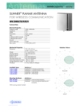
EBS862
1 Electronic unit cover
2 Lifting eye
3 Commissioning and service field
4 Cover screws
5 Cover hinges
6 Tap holes for cable entries
7 Ground terminal
8 Terminals (power supply)
9 Terminals (motor cable)
0 Binary output fuses
k Terminals (signals)
l Lower part of electronic unit
Figure 3: Presentation without cover for terminal compartment
The EBS862 electronic unit is made up of two housing halves
(electronic cover / electronic unit lower part) which can be
separated for easier assembly.

10 EBS852 / EBS862 ELECTRONIC UNIT | OI/EBS852/EBS862/EX-EN REV. B
… 3 Design and function
Principle of operation
The electronic unit builds the interface between the actuator and
the control system.
During continuous positioning, the electronic unit varies the
motor torque continuously until the actuator force and the
control valve force are balanced. High response sensitivity and
high positioning accuracy with short positioning time ensure an
excellent control quality and a long actuator life.
Electronic units are available for assembly in the field near the
actuator, remotely in a mounting rack or for integrated assembly
(smallest actuator type). In addition to the terminals, the
electronic unit contains the microprocessor, frequency converter
for motor control, analog and binary inputs and outputs,
PROFIBUS® or HART® communication interfaces, the
commissioning and service field and a plug connection to
connect a PC.
No matter what the motor power of the respective actuator is,
all electronic units are supplied single-phase by 230 V or 115 V
mains supply (50 Hz or 60 Hz).
The commissioning and service field enables the end positions
and direction of rotation to be set on the actuator. Moreover,
status information is displayed using LEDs. Push buttons can be
used to operate the actuator and set the operating mode
(Automatic, Out of Service).
Change from two to one column

EBS852 / EBS862 ELECTRONIC UNIT | OI/EBS852/EBS862/EX-EN REV. B 11
Device designs
EBS852
IP rating IP 20
Humidity ≤ 75 % annual average; condensation not permitted
Rack air inlet temperature 0 to 45 °C (32 to 113 °F)
Transport and storage temperature −25 to 70 °C (−13 to 158 °F)
Long-term storage temperature −25 to 40 °C (−13 to 104 °F)
Mounting position vertical; lateral connections, right
Vibration stress 2 to 9 Hz: maximum deflection: 3 mm (0.12 in)
9 to 200 Hz: acceleration: 1 g
Paint 2-layer component epoxy (RAL 9005, black)
Electrical connection Mains supply via screw terminals; all other connections made via screw-type plug connectors
Maximum cable length electronic unit – actuator: *
270 m at 1.5 mm
2
(885 ft at 16 AWG)
460 m at 2.5 mm
2
(1510 ft at 14 AWG)
Weight 11 kg (24 lbs)
* The maximum cable length depends on the actuator type and cable cross-section, see Rotary actuators on page 22.
EBS862
IP rating IP 20
Humidity ≤ 75 % annual average; condensation not permitted
Rack air inlet temperature 0 to 45 °C (32 to 113 °F)
Transport and storage temperature −25 to 70 °C (−13 to 158 °F)
Long-term storage temperature −25 to 40 °C (−13 to 104 °F)
Mounting position vertical, cable glands down
Vibration stress 2 to 9 Hz: maximum deflection: 3 mm (0.12 in)
9 to 200 Hz: acceleration: 1 g
Paint 2-layer component epoxy (RAL 9005, black)
Electrical connection Mains supply via screw terminals; all other connections made via screw-type plug connectors
Maximum cable length electronic unit – actuator: *
470 m at 10 mm
2
(1542 ft at 8 AWG)
Weight 40 kg (88 lbs)
* The maximum cable length depends on the actuator type and cable cross-section, see Rotary actuators on page 22.
Change from one to tw o columns

12 EBS852 / EBS862 ELECTRONIC UNIT | OI/EBS852/EBS862/EX-EN REV. B
4 Product identification
M10441
Elektronik / Electronics Type: ...
Made in Germany
B-Nr./No. ...... NL
U = 23 0 V .. . Jahr/Year
f = 5 0/60 Hz ± 5 % P= max.... .. W
t = . ... .......... ... .°C IP 20
CE
Ext. Sicherung / Fuse ... ....
D-32425 Mind
en
ABB Automation Products GmbH
Schillerstrasse 72
1
2
3
4
5
6
7
l
k
j
9
8
1 Full type designation
2 Manufacturing number
3 Power supply
4 Permissible mains frequency
5 Ambient temperature range
6 Specifications for external fuse
protection
7 Manufacturer address
8 CE mark
9 IP rating
0 Maximum power consumption
k Year of manufacture
l NL no. (for no-list design)
Figure 4: Hardware name plate (example)
M10361
Für / For
Antrieb /Actuator
Nennwerte /Rated Values
M=
F-Nr. / No.
Software Version
NL.
°/s=
1
2
3
4
5
6
1 Associated Contrac control
actuator
2 Nominal torque or rated
actuator strength / set speed
3 Manufacturing number
4 NL no. (for no-list design)
5 Installed software version
6 Free for customer-specific
information
Figure 5: Software name plate (example)
Note
In electronic units which can be separated for assembly, the
name plate for the hardware is located on the lower part of the
electronic unit (Figure 1). The name plate for the software
(Figure 2) and an additional name plate for the hardware
(Figure 3) are located on the electronic unit cover.
The lower part of the electronic unit and the electronic cover are
independent assemblies, therefore the respective
manufacturing numbers can differ.
M10443M10443
Elektronik / Electronics Type: ...
Made in Germany
B-Nr./No. ...... NL
Jahr/Year
t = . ... .......... ... .°C IP 20
CE
D-32425 Mind
en
ABB Automation Products GmbH
Schillerstrasse 72
1
2
3
4
8
7
6
5
1 Full type designation
2 Manufacturing number
3 Ambient temperature range
4 Manufacturer address
5 CE mark
6 IP rating
7 Year of manufacture
8 NL no. (for no-list design)
Figure 6: Additional name plate for hardware (example)
Scope of delivery
EBS852
• Cable clamps for strain relief of the connection cable
EBS862
• Metric tap holes for cable entries with IP 66 sealing plugs

EBS852 / EBS862 ELECTRONIC UNIT | OI/EBS852/EBS862/EX-EN REV. B 13
Delivery status
The individual actuator configuration may vary from the
standard setup above. This information can be displayed via the
user interface.
Unless otherwise specified by the user, the electronic units are
delivered with the following standard configuration:
Conventional communication
Parameter Setting
Function selection Positioner, parameter: set point
Set point function Analog set point
Set point range 4 to 20 mA
Set point characteristic Linear; set point = position value
Actual value range 4 to 20 mA
Nominal torque / rated force in
±direction
100 %
Automatic speed in ±direction: 100 %
Action in 0 % / 100 % end
position
Keep leak-tight with nominal torque / rated
force
Digital inputs Digital input 1 Manual / Automatic
switching,
Digital input 2 / 3 Travel command ±
Digital outputs Digital output 1 ready for operation / error
message,
Digital output 2 / 3 end position signaling 0
% / 100 %
Brake Away Function Deactivated
Shut-off function Deactivated
Positioning loop monitoring Deactivated
Set point monitoring Deactivated
Alarm Type Deactivated
Action after restoration of
power
Switch to Automatic
Working range of actuator Not set
5 Transport and storage
Inspection
Check the devices immediately after unpacking for possible
damage that may have occurred from improper transport.
Details of any damage that has occurred in transit must be
recorded on the transport documents.
All claims for damages must be submitted to the shipper
without delay and before installation.
Transporting the device
Safety instructions
DANGER
Danger to life due to falling or toppling loads.
Risk of death or serious injury due to the device falling down
or toppling over!
• Standing under suspended loads is prohibited.
• Do not detach the hoisting equipment until installation is
complete.
• Only use the dedicated load pick-up devices (eyebolts) for
suspending the components.
Consider the following items during transport:
• Pay attention to the device weight details.
• Do not expose the device to humidity during transport.
Pack the device accordingly.
• Pay attention to the permissible transportation
temperatures for the device.
Returning devices
For the return of devices, follow the instructions in Repair on
page 38.
Storing the device
The electronic units EBS852 / EBS862 comply with IP rating IP 20.
The electronic units should be stored in accordance with this IP
rating. Condensation is not permitted.
The permissible storage temperatures as well as the ambient
conditions (humidity) should be complied with (see Device
designs on page 11).
For longer storage periods, we recommend packing the units in
foil with a dessicant added.
The dessicant must be checked for regularly for effectivity.

14 EBS852 / EBS862 ELECTRONIC UNIT | OI/EBS852/EBS862/EX-EN REV. B
6 Installation
Mounting
NOTICE
Damage to components!
Damage to components caused by ingress of foreign bodies
or humidity.
• Keep all housing covers and terminal compartments
closed during installation to prevent the ingress of foreign
bodies such as drilling shavings, liquids or dust.
The electronic unit is installed in the vicinity of the drive outside
the hazardous area. Screw-type terminals are used to connect
the two modules on the actuator side and on the electronics
side.
The cables are connected to the actuator through two terminal
compartments:
• Motor connection compartment (Ex d)
• Sensor terminal compartment (through Ex e terminals)
The SD241-B motor temperature monitoring unit or a similar,
certified tripping unit must be connected to the power supply of
the electronic unit.
The motor temperature monitoring unit must be installed
outside of the potentially explosive atmosphere.
When installing the electronic unit, observe the following points:
• You must be able to activate the power supply of the
electronic unit on-site.
• All signal cables and the motor cable between the
actuator and electronic unit must be shielded.
• The cable shield must be placed on both housings when
connecting the electronic unit and the actuator.
• The maximum vibration load must be observed during
installation, see Device designs on page 11.
• When mounting the electronic unit in work and traffic
areas that may be accessed by unauthorized persons, the
operator is required to take suited protective measures.
EBS852
1. Fasten the electronic unit to the vertical mounting rail of the
mounting rack using grade 8.8 screws. Tensile strength 800
N/mm
2
(116032 pounds/square in.), yield strength 640
N/mm
2
(92826 pounds/square in.).
2. Provide adequate room for installation and ensure easy
access.
3. The cable entries must be directed to the right.

EBS852 / EBS862 ELECTRONIC UNIT | OI/EBS852/EBS862/EX-EN REV. B 15
EBS862
Note
The total weight of the electronic unit is 40 kg (88 lbs). For this
reason, the electronic unit is equipped with a load-bearing
eyelet.
If, for technical reasons, the load-bearing eyelet cannot be used,
the two halves of the housing can be installed separately.
Separating the housing halves
1. Place the electronic unit on a horizontal surface.
2. Unscrew the cover screws(Figure 3).
3. Flip open the electronic unit cover.
4. Disconnect the internal plug connection between the housing
halves.
5. Close the electronic unit cover.
6. Unscrew the hinge screw (Figure 3).
7. Flip the electronic unit cover forward while lifting it up and
off the hinge pin. Precisely guide the cover of the electronic
unit cover in the process.
Mounting
1. Fasten the electronic unit or the lower part of the electronic
unit to the vertical mounting rail of the mounting rack using
grade 8.8 screws. Tensile strength 800 N/mm
2
(116032 pounds/square in.), yield strength 640 N/mm
2
(92826 pounds/square in.).
2. Provide adequate room for installation and ensure easy
access.
3. The cable entries must be directed down.
Mounting the housing halves
1. Set the electronic unit cover down on the hinge pin and screw
in the hinge screw. Precisely guide the cover of the electronic
unit cover in the process.
2. Reconnect the internal plug connection.
3. Close the electronic unit cover and screw in the cover screws
(Figure 3).
Assembly and cable routing in the mounting rack
When installing the electronic units in a mounting rack (on site),
we recommend laying the cables in accordance with the
following illustrations.
Front view Side view
M10446
1 1
2
3
4
4
3
Top view
1 Electronic units
2 Thermally conductive plates
3 Mains distribution
4 Cable guiding
Figure 7: Installing the electronic unit and guiding the cable in the mounting rack
(example)
Change from two to one column

16 EBS852 / EBS862 ELECTRONIC UNIT | OI/EBS852/EBS862/EX-EN REV. B
… 6 Installation
Dimensions
Electronic unit EBS852 (Contrac)
M10218
285 (11.22)
28,5 (1.12)
15,5 (0.61)
91 (3.58)
312 (12.28)
58 (2.28)
17 (0.67)
25 (0.98)
22 (0.87)
40
(1.57)
5 (0.2)
87 (3.43)
10 (0.39)
41 (1.61)
190 (7.48)
290 (11.42)
99 (3.9)
9 (0.35)
255 (10.03)
9 (0.35)
79 (3.11)
20 (0.79)
20 (0.79)
40 (1.57)
62 (2.44)
28 (1.10)
40 (1.57)
20 (0.79)
15 (0.59)
135 (5.31)
153 (6.02)
30
(1.18)
130 (5.12)
34
(1.34)
40
(1.57)
Figure 8: Dimensions in mm (in)

EBS852 / EBS862 ELECTRONIC UNIT | OI/EBS852/EBS862/EX-EN REV. B 17
Electronic unit EBS862 (Contrac)
M10187
100 (3.94)
35 (1.38)
75 (2.95)
97,5 (3.84)
386 (15.20)
444 17.48)
370 (14.57)
399 (15.71)
30 (1.18)
30 (1.18)
339 (13.35)
262 (10.31)
36 (1.42)
20 (0.79)
29 (1.14)
470 (18.50)
35 (1.38)
600 (23.62)
9 (0.35)
c
b
a
1 Front section open, rotated 90°
2 Rotational radius
3 Tap holes
Figure 9: Dimensions in mm (in)

18 EBS852 / EBS862 ELECTRONIC UNIT | OI/EBS852/EBS862/EX-EN REV. B
… 6 Installation
… Dimensions
Fuses
Thermal circuit breaker Safety fuse
(1.77)
(0.49)
(1.71)
(1.57)
(3.09)
(1.73)
(3.48)
(1.89)
(3.15)
(1.65)
(0.35)
(3.50)
(0.79)
45
20
12,5
43,5
40
78,5
44
88,5
48
80
42
9
89
M10220
Figure 10: Dimensions in mm (in)
Change from one to tw o columns

EBS852 / EBS862 ELECTRONIC UNIT | OI/EBS852/EBS862/EX-EN REV. B 19
7 Electrical connections
Safety instructions
WARNING
Risk of injury due to live parts!
When the housing is open, contact protection is not provided
and EMC protection is limited.
• Before opening the housing, switch off the power supply.
WARNING
Danger due to electric current!
Danger of electric shock by residual voltage at the terminals
after switching off the power supply.
• Before opening the terminal compartment, switch off the
power supply and wait for > 2 minutes.
NOTICE
Damage to the device due to improper handling!
• When replacing the defective safety fuses, only fuses with
types and characteristics should be used (see Fuses on
page 39).
The electrical connection may only be established by authorized
specialist personnel.
Notices on electrical connection in this instruction must be
observed; otherwise, electric safety and the IP-rating may be
adversely affected.
Safe isolation of electric circuits which are dangerous if touched
is only guaranteed when the connected devices fulfill the
requirements of EN 61140 (basic requirements for secure
separation).
To ensure safe isolation, install supply lines so that they are
separate from electrical circuits which are dangerous if touched,
or implement additional isolation measures for them.
General
Each actuator requires a suited Contrac electronic unit with
installed actuator-specific software. Observe the information in
the operating instruction. The specifications on the name plates
of the electronic unit and actuator must match to guarantee
correct hardware and software allocation.
Please observe the following information when installing the
cable set:
• The specific regulations governing the installation of
electric systems in potentially explosive atmospheres
must be observed during electric installation work. The
provisions in accordance with EN 60079-14 must be
observed, particularly in respect of installing the shield
bonding and potential equalization between the actuator,
electronic unit, and motor protection equipment, see
Connection of cable shielding on page 29.
• The motor and position sensor may only be connected
using IP 66 Ex cable glands in accordance with EN 60079
ff with EU type examination certificate in accordance
with Directive 2014/34/EU.
• Use a cable lug or a solid wire, bended to a ‘U’, to connect
the motor cable
• Make sure that sufficient strain relief measures are in
place for all cable connections.
• Protect all cables in the connection chambers sufficiently
against contact with metal components. Guarantee a gap
of at least 6 mm (0.24 in) between all conductive
components.
• Remove the desiccant in the connection chamber of the
motor and position sensor.
• Do not change the factory-set installation position of the
motor junction box.
• Close off any cable entries that are not required using
ATEX-certified IP 66 sealing plugs.
Conductor cross-section on control
actuator
Screw terminals
Motor/brake max. 2.5 mm
2
(14 AWG)
Signals max. 2.5 mm
2
(14 AWG)

20 EBS852 / EBS862 ELECTRONIC UNIT | OI/EBS852/EBS862/EX-EN REV. B
… 7 Electrical connections
Conductor cross-section on electronic unit
Note
Detailed information on separate electronic units can be found
in the corresponding data sheets.
EBS852 – Clamping connection
Suited for cable Ø
Terminals for conductor
cross-section
Mains cable 13 mm (0.51 in) max. 4 mm
2
(12 AWG)
Signal cable (DCS) 8 mm (0.31 in) max. 1.5 mm
2
(16 AWG)
Transmitter (option) 8 mm (0.31 in) max. 1.5 mm
2
(16 AWG)
Motor cable 13 mm (0.51 in) max. 4 mm
2
(12 AWG)
Sensor cable 8 mm (0.31 in) max. 1.5 mm
2
(16 AWG)
EBS862 – Clamping connection
Terminals for conductor cross-section
Mains cable max. 6 mm
2
(10 AWG)
Signal cable (DCS) max. 4 mm
2
(12 AWG)
Transmitter (option) max. 4 mm
2
(12 AWG)
Motor cable max. 6 mm
2
(10 AWG)
Sensor cable max. 4 mm
2
(12 AWG)
Cable glands
DANGER
Risk of explosion!
Risk of explosion due to the use of unsuitable cable glands.
• The cable glands used must be approved for type of
protection ‘Ex e – increased safety’.
• The cable glands used must guarantee correct contact of
the cable shielding.
The actuators and electronic units are supplied without cable
glands. Suited cable glands must be installed on site.
Tap holes for cable glands
metric
Power supply M20 × 1.5 (1 ×)
Signal cable M20 × 1.5 (3 ×)
Motor cable M25 × 1.5 (1 ×)
Selection of suited connection cables
Please observe the following information when selecting cables:
• Use suited cables only for the electric connection
between the Contrac control actuator in potentially
explosive atmospheres and the components outside of
the potentially explosive atmospheres.
• Use shielded cables for the motor / brake cable, the
sensor cable, and the signal cable to the control system /
controller.
• Connect the shielding of the motor / brake cable and the
sensor cable on both sides (to the actuator and to the
Contrac electronic unit).
• For the connection between the motor and motor
temperature monitoring unit and for the power supply,
shielded cables are not required.
Installation information on the cable harness for actuators in
Ex design
The electrical connection between the Contrac electronic unit
and the Contrac actuator can be established using the cable set
(order code 695). The cable harness is not part of the Ex
prototype test certificate and must therefore be tested for
safety-relevant functionality within the complete installation by
the installer or operator.
If the specified cable harness does not meet all safety-relevant
requirements, the proper installation material must be used.
For the specified motor connection cable, the shielding must be
connected at both ends and connected with protective ground.
/