Page is loading ...

Operating Instructions
42/68-166-EN
Electrical Part Turn Actuato
r
RHD8000 ... 16000
Pos: 1 /Titelblätter / Copyright/BA-I A/Aktorik/Antriebe/C ontrac/RHD8000-16000 ( Contrac) @ 14\mod_119 4246762265_3101.doc @ 135117
Rated torque
8000 ... 16000 Nm (6000 ... 12000 lbf-ft)
P R
O
F I
B
U S
PROCESS FIELD BUS
®

Blinder Text
2 RHD8000 ... 16000 42/68-166-EN
Pos: 2 /Titelblätter / Copyright/Copyr ight-Seite @ 0\mod_113878 1938968_3101.doc @ 3122
Electrical Part Turn Actuator
RHD8000 ... 16000
Operating Instructions
42/68-166-EN
02.2008
Rev. D
Manufacturer:
ABB Automation Products GmbH
Schillerstraße 72
32425 Minden
Germany
Tel.: +49 551 905-534
Fax: +49 551 905-555
[email protected]b.com
© Copyright 2008 by ABB Automation Products GmbH
Subject to change without notice
This document is protected by copyright. It assists the user with the safe and efficient operation of the
device. The contents may not be copied or reproduced in whole or in excerpts without prior approval of
the copyright holder.
Pos: 3 /Inhaltsverzeic hnis/Inhalts verzeichnis für alle Doku mente @ 0\mod_113871031089 0_3101.doc @ 3129
Contents

Contents
42/68-166-EN RHD8000 ... 16000 3
1
Safety....................................................................................................................................................................5
1.1 General Safety Information ............................................................................................................................5
1.2 Technical limits...............................................................................................................................................5
1.3 Warranty provision .........................................................................................................................................6
1.4 Labels and symbols........................................................................................................................................6
1.4.1 Symbols and warnings............................................................................................................................6
1.4.2 Name plate..............................................................................................................................................7
1.5 Operator liability .............................................................................................................................................7
1.6 Personnel qualification ...................................................................................................................................7
1.7 Returning devices...........................................................................................................................................8
1.8 Disposal..........................................................................................................................................................8
1.8.1 Information on WEEE directive 2002/96/EC (Waste Electrical and Electronic Equipment) ...................8
1.9 Transport safety information ..........................................................................................................................8
1.10 Storage conditions..........................................................................................................................................9
1.11 Installation safety information.........................................................................................................................9
1.12 Electrical installation safety information .........................................................................................................9
1.13 Operating safety information ........................................................................................................................10
1.14 Maintenance safety information ...................................................................................................................10
2 Design and function..........................................................................................................................................11
3 Installation..........................................................................................................................................................12
3.1 Actuator check..............................................................................................................................................12
3.2 Mounting position .........................................................................................................................................12
3.3 Installation instructions.................................................................................................................................13
3.4 Assembly with the valve...............................................................................................................................13
3.4.1 Preparation............................................................................................................................................13
3.4.2 Adjusting the stops in dependence of the travel ...................................................................................14
3.4.3 Adjusting the stops in dependence of the torque..................................................................................14
3.5 Mounting examples ......................................................................................................................................15
3.5.1 Fastening elements...............................................................................................................................15
3.5.2 Mounting with lever ...............................................................................................................................16
3.6 Dimensioned drawings.................................................................................................................................17
3.6.1 Lever for RHD8000 ...............................................................................................................................17
3.6.2 Lever for RHD16000 .............................................................................................................................19
4 Electrical connection ........................................................................................................................................21
4.1 Cable shield..................................................................................................................................................21
4.1.1 Signal part .............................................................................................................................................21
4.2 Terminal connection diagrams .....................................................................................................................22
4.2.1 Power Electronic Unit EBS853 (Contrac) / EBS861 (Contrac).............................................................22
4.2.2 Analog / digital.......................................................................................................................................22

Contents
4 RHD8000 ... 16000 42/68-166-EN
4.2.3 PROFIBUS DP......................................................................................................................................23
4.2.4 Power Electronic Unit EBS852 (Contrac) / EBS862 (Contrac).............................................................24
4.2.5 Analog / digital.......................................................................................................................................24
5 Operation............................................................................................................................................................25
5.1 Automatic / manual mode.............................................................................................................................25
5.2 Manual operation..........................................................................................................................................25
6 Maintenance.......................................................................................................................................................26
6.1 Inspection and overhaul ...............................................................................................................................26
6.2 Brake adjustment .........................................................................................................................................27
6.3 Oil change ....................................................................................................................................................27
6.4 Filling capacity..............................................................................................................................................28
7 Trouble shooting ...............................................................................................................................................29
7.1 Electrical test values.....................................................................................................................................29
8 Technical data....................................................................................................................................................30
8.1 General information......................................................................................................................................30
8.2 Technical data RHD8000 .............................................................................................................................30
8.3 Technical data RHD16000 ...........................................................................................................................31
9 Appendix ............................................................................................................................................................32
9.1 Permits and certifications .............................................................................................................................32
10 Index ...................................................................................................................................................................34

Safety
42/68-166-EN RHD8000 ... 16000 5
Pos: 4.1 /Überschri ften/1/S - U/Sic herheit @ 0\mod_1129703894050_3 101.doc @ 3168
1 Safety
Pos: 4.2 /Sicher heit/Allgemein/Allge meines zur Sicherhei t @ 0\mod_1129703939516_310 1.doc @ 3260
1.1 General Safety Information
The “Safety” chapter provides an overview of the safety aspects to be observed for the
operation of the device.
The device is built based on state-of-the-art technology and is operationally safe. It was tested
and left the factory in a proper state. The requirements in the manual as well as the
documentation and certificates must be observed and followed in order to maintain this state for
the period of operation.
The general safety requirements must be complied with completely during operation of the
device. In addition to the general information, the individual chapters of the manual contain
descriptions about processes or procedural instructions with specific safety information.
Only the observance of all safety information enables the optimal protection of personnel as well
as the environment from hazards and the safe and trouble-free operation of the device.
Pos: 4.3 /Sicher heit/Aktorik/Elektr . Schwenkantriebe/A llgemein/Bestim mungsgemäße Verwendung RHD @ 16\ mod_1197272116328_310 1.doc @ 144907
The actuators are used for operating final control elements (valves, vanes, etc.). They may only
be operated using the appropriate Contrac electronic unit. Do not use these actuators for any
other purpose. Otherwise, a hazard of personal injury or of damage to or impairment of the
operational reliability of the device may arise. In addition to these operating instructions, the
relevant documentation for the electronic unit and software tools must be observed.
Pos: 4.4 /Sicher heit/Allgemein/Hinweis zur bestimmungswidr igren Verwendung (War tung/Reparatur) @ 0\ mod_1129707002440_3101.d oc @ 3240
Repairs, alterations and enhancements or the installation of replacement parts is only
permissible as far as described in the manual. Further actions must be verified with ABB
Automation Products GmbH. Excluded from this are repairs performed by ABB-authorized
specialist shops.
Pos: 4.5 /Sicher heit/Temperatur/Allge mein/Technische Gren zwerte (Temperatur) BA @ 0\mod_1140156564953_310 1.doc @ 3252
1.2 Technical limits
The device is designed for use exclusively within the stated values on the name plate and in the
technical specifications (see "Technical Specifications” chapter and data sheet). These must be
complied with accordingly, e.g.:
• The maximum operating temperature may not be exceeded.
• The permitted operating temperature may not be exceeded.
• The housing protection system must be observed.
Pos: 4.6 /====== = Seitenumbruch ======== @ 0\mod_11265 32365768_3101.doc @ 3830

Safety
6 RHD8000 ... 16000 42/68-166-EN
Pos: 4.7 /Sicher heit/Allgemein/Gewähr leistungsbestimmun gen @ 0\mod_1129706207246 _3101.doc @ 3261
1.3 Warranty provision
A use contrary to the device’s stipulated use, disregarding of this manual, the use of under-
qualified personnel as well as unauthorized alterations excludes the manufacturer of liability
from any resulting damages. The manufacturer’s warranty expires.
Pos: 4.8 /Überschri ften/1.1/1-spalti g/S - U/Schilder und Symbo le @ 0\mod_1129721947139 _3101.doc @ 3204
1.4 Labels and symbols
Pos: 4.9 /Sicher heit/Allgemein/Symbol e und Signalwörter @ 0\mod_1 129716750196_3101. doc @ 3244
1.4.1 Symbols and warnings
Danger – <Serious damage to health / risk to life>
One of these symbols in conjunction with the “Danger“ warning indicates an imminent danger.
If it is not avoided, death or serious injury will result.
Warning – <Bodily injury>
The symbol in conjunction with the “Warning“ message indicates a possibly dangerous
situation. If it is not avoided, death or serious injury could result.
Caution – <Slight injuries>
The symbol in conjunction with the “Caution“ message indicates a possibly dangerous
situation. If it is not avoided, slight or minor injury can result. May also be used for property
damage warnings.
Notice – <Property damage>!
The symbol indicates a possibly damaging situation. If it is not avoided, the product or
something in its area can be damaged.
Important
The symbol indicates operator tips or especially useful information. This is not a message for a
dangerous or damaging situation.
Pos: 4.10 /====== = Seitenumbruch ======= = @ 0\mod_1126532365768_3101.doc @ 3830

Safety
42/68-166-EN RHD8000 ... 16000 7
Pos: 4.11 /Überschri ften/1.1.1/1-spal tig/Typenschild @ 0\mod_1140617210906_3 101.doc @ 3227
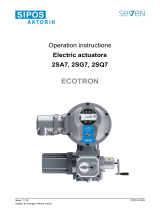
1.4.2 Name plate
Pos: 4.12 /Sicher heit/Aktorik/Allge mein/Typenschild @ 14\ mod_1194257536484_3101. doc @ 135582
M00365
Antrieb / Actu ator: CONTRAC ....
F-Nr./No NL
M = Jahr/Year
CE
t= IP66
min......max. ....... max. .........
Öl
Elektronik/Electronics
/ Oil:
ABB Automation
D-32425 Minden
Made in Germany
1
2
3
4
5
6
7
8
9
10
Fig. 1
1 Complete model name
2 Fabrication no./ NL no. (no. of non-
standard version)
3 Output torque / Year of manufacture
4 Permissible ambient temperature and
protection class / CE mark
5 min./max. crank angle and max.
actuating speed
6 Filled oil types
7 Associated Contrac electronic unit
8 Free
9 Free
10 Free for customer-specific entry
Pos: 4.13 /Sicher heit/Aktorik/Allge mein/Pflichten des Be treibers @ 10\mod_118172 3170562_3101.doc @ 105157
1.5 Operator liability
The operators must strictly observe the applicable national regulations in their countries with
regards to installation, function tests, repairs, and maintenance of electrical devices.
Pos: 4.14 /Sicher heit/Allgemein/Organis atorische Maßnah men/Qualifikation des Per sonals @ 0\mod_1129728 800194_3101.doc @ 3247
1.6 Personnel qualification
The installation, commissioning and maintenance of the device may only be carried out through
trained specialist personell authorized by the plant operator. The specialist personnel must have
read and understood the manual and comply with its instructions.
Pos: 4.15 /====== = Seitenumbruch ======= = @ 0\mod_1126532365768_3101.doc @ 3830

Safety
8 RHD8000 ... 16000 42/68-166-EN
Pos: 4.16 /Sicher heit/Allgemein/Organis atorische Maßnah men/Rücksendung von Gerä ten @ 0\mod_1129730744499 _3101.doc @ 3248
1.7 Returning devices
Use the original packaging or a suitably secure packaging for returning the device for repair or
for recalibration. Include the properly filled out return form (see attachment) with the device.
According to EC guidelines for hazardous materials, the owner of hazardous waste is
responsible for its disposal or must observe the following regulations for its shipping:
All delivered devices to ABB Automation Products GmbH must be free from any hazardous
materials (acids, alkali, solvents, etc.).
Pos: 4.17 /Sicher heit/Allgemein/Organis atorische Maßnah men/Entsorgung @ 10\mod_11764 47410937_3101.doc @ 81544
1.8 Disposal
ABB Automation Products GmbH actively promotes environmental consciousness and has an
operational management system in accordance with DIN EN ISO 9001:2000, EN ISO
14001:2004 and OHSAS 18001. Our products and solutions should have minimum impact on
the environment and persons during manufacture, storage, transport, use and disposal.
This includes the environmentally friendly use of natural resources. Through its publications
ABB conducts an open dialog with the public.
This product/solution is manufactured from materials that can be reused by specialized
recycling companies.
1.8.1 Information on WEEE directive 2002/96/EC (Waste Electrical and Electronic Equipment)
This product/solution is not subject to the WEEE directive 2002/96/EC and relevant national
laws (e.g., ElektroG in Germany).
Dispose of the product/solution directly in a specialized recycling facility and do not use the
municipal garbage. Only privately used products may be disposed of in the municipal garbage
according to the WEEE directive 2002/96/EC. Proper disposal prevents negative effects on
people and the environment, and supports the reuse of valuable raw materials.
If it is not possible to dispose of old equipment properly, ABB Service can accept and dispose of
returns for a fee.
Pos: 4.18 /Überschri ften/1.1/1-spa ltig/S - U/Sicherheitshi nweise zum Transpor t @ 0\mod_1140166475703_3 101.doc @ 3206
1.9 Transport safety information
Pos: 4.19 /Transport/ Allgemein/Prüf ung @ 0\mod_1129815371197_3 101.doc @ 3317
Check the devices for possible damage that may have occurred from improper transport.
Damages in transit must be recorded on the transport documents. All claims for damages must
be claimed without delay against the shipper and before the installation.
Pos: 4.20 /====== = Seitenumbruch ======= = @ 0\mod_1126532365768_3101.doc @ 3830

Safety
42/68-166-EN RHD8000 ... 16000 9
Pos: 4.21 /Überschri ften/1.1/1-spa ltig/J - L/Lagerbedingunge n @ 8\mod_11769070169 21_3101.doc @ 84229
1.10 Storage conditions
Pos: 4.22 /Sicher heit/Aktorik/Elektr . Schwenkantriebe/A llgemein/Lagerbedin gungen @ 9\mod_1181415663 015_3101.doc @ 102780
The actuators may be stored under moist and aggressive condition for a short time. The
equipment is protected against external corrosive influences. However, direct exposure to rain,
snow, etc., must be avoided.
Actuators, equipped with an anti condensation heater, are additionally protected by desiccant,
which is placed in the following locations:.
Position sensor: in connection chamber
electronic unit (separately supplied): electrical connection area
The desiccant guarantees sufficient protection for approximately 150 days. It can be
regenerated at a temperature of 90 °C (114 °F) within 4 h.
Important
Remove the desiccant prior to commissioning the actuator or the electronic unit.
If you intend to store or transport the device for a longer time, we recommend that you wrap it in
plastic foil and add desiccant. Regularly check whether the desiccant is still active.
Pos: 4.23 /Überschri ften/1.1/1-spa ltig/S - U/Sicherheitshi nweise zur Montage @ 0\mod _1140166528109_3101.doc @ 3208
1.11 Installation safety information
Pos: 4.24 /Sicher heit/Aktorik/Elektr . Schwenkantriebe/A llgemein/Sicherhei tshinweise zur Montage @ 10\ mod_1181563348656_3 101.doc @ 102853
• The actuators perform movements for positioning vanes and valves, etc.
• Only qualified specialists who have been trained for these tasks are authorized to mount and
adjust the control actuator, and to make the electrical connection.
• When working on the actuator itself or the electronics always observe the locally valid
accident prevention regulations and the regulations concerning the construction of technical
installations.
• The eyebolt at the top of the actuator may only be used to lift or lower the actuator vertically.
• Do not use the handwheel to lift or to lower the actuator..
• Do not use it if the actuator is mounted at the valve! Make sure that the final control element
is not exposed to process forces.
Pos: 4.25 /Überschri ften/1.1/1-spa ltig/S - U/Sicherheitshi nweise zur elektrisc hen Installation @ 0\mo d_1140166567843_310 1.doc @ 3207
1.12 Electrical installation safety information
Pos: 4.26 /Sicher heit/Temperatur/Al lgemein/Sicherheits hinweise zur elektri schen Installation ( Temperatur) @ 13\mod_119 1930430247_3101. doc @ 128893
The electrical connection may only be performed by authorized specialist personnel according
to the electrical plans.
Comply with electrical connection information in the manual. Otherwise, the electrical protection
class can be affected.
The secure separation of contact-dangerous electrical circuits is only guaranteed when the
connected devices fulfill the requirements of the DIN EN 61140 (VDE 0140 Part 1) (basic
requirements for secure separation).
For secure separation, run the supply lines separated from contact-dangerous electrical circuits
or additionally insulate them.
Pos: 4.27 /====== = Seitenumbruch ======= = @ 0\mod_1126532365768_3101.doc @ 3830

Safety
10 RHD8000 ... 16000 42/68-166-EN
Pos: 4.28 /Überschri ften/1.1/1-spa ltig/S - U/Sicherheitshi nweise zum Betrieb @ 0\mod_11 40166424437_3101. doc @ 3205
1.13 Operating safety information
Pos: 4.29 /Sicher heit/Aktorik/Elektr . Schwenkantriebe/ Allgemein/Sicherhei tshinweise zum Betri eb RHD @ 16\mod_11972722727 96_3101.doc @ 144931
Warning - risk of injury!
Note that the actuator position may be changed accidentally by the repelling power of the
valve when the brake is released!
Before switching on, ensure that the specified environmental conditions in the “Technical
Specifications” chapter or data sheet are complied with and that the power supply voltage
corresponds with the power electronic unit.
When there is a chance that safe operation is no longer possible, put the device out of operation
and secure against unintended operation.
When mounting the actuator in areas which may be accessed by unauthorized persons, take
the required protective measures.
Switch off the power supply to the motor prior for manual operation.
Pos: 4.30 /Überschri ften/1.1/1-spa ltig/S - U/Sicherheitshi nweise zur War tung @ 10\mod_1181811822343_310 1.doc @ 106052
1.14 Maintenance safety information
Pos: 4.31 /Sicher heit/Aktorik/Elektr . Schwenkantriebe/A llgemein/Sicherhei tshinweise zur War tung @ 10\mod_1181812046750_ 3101.doc @ 106075
• When changing the oil of the actuator, thoroughly remove any oil that may have run down on
the floor during the procedure to avoid accidents.
• Dispose of the waste oil in compliance with the respective local regulations. Make sure that
no oil reaches the water cycle.
• Switch off the supply voltage for the power electronic unit and separate anti-condensation
heater (option) when working on the actuator or related subassemblies and take precautions
to prevent unintentional switch-on.
• Make sure that any oil leaking from the device cannot come into contact with hot parts
Pos: 5 /======= Seitenumbr uch ======== @ 0\mod_1126 532365768_3101.doc @ 3830

Design and function
42/68-166-EN RHD8000 ... 16000 11
Pos: 6.1 /Überschri ften/1/A - C/Auf bau und Funktion @ 0\mod_112979762073 3_3101.doc @ 3140
2 Design and function
Pos: 6.2 /Aufbau und Funkti on/Aktorik/Elektr . Schwenkantriebe/ RHD8000...16000/A ufbau RHD8000...16000 @ 14\mod_1194 606461296_3101.doc @ 137975
M00306
4
1
2
9
10
8
3
6
5
7
Fig. 2: RHD8000...RHD16000 (illustrations may differ from actual installation)
1 Ball-and-socket joint
2 Damper lever
3 Hand wheel crank
4 Hand wheel
5 Hand wheel release
6 Servo motor
7 Intermediate gears
8 Gear case
9 Adjustable stops
10 Output shaft
Pos: 6.3 /Aufbau und Funkti on/Aktorik/Elektr . Schwenkantriebe/ Allgemein/Konzep t @ 15\mod_1195050522390_31 01.doc @ 140463
Functionality
Compact actuator for the operation of final control elements with preferably 90° rotary
movement such as flaps, cocks, etc.
The torque is transferred via a lever / linkage bar assembly or the actuator is directly coupled to
the cock flange.
A special power electronic unit controls the actuator. The electronic unit serves as the interface
between actuator and control system.
During continuous positioning the power electronic unit varies the motor torque steplessly until
the actuator force and the restoring process forces are balanced. High response sensitivity and
high positioning accuracy with short positioning time ensure an excellent control quality and a
long actuator life.
Pos: 7 /======= Seitenumbr uch ======== @ 0\mod_1126 532365768_3101.doc @ 3830

Installation
12 RHD8000 ... 16000 42/68-166-EN
Pos: 8.1 /Überschri ften/1/M - O/Montage @ 0\mod_11 40519732218_3101. doc @ 3159
3 Installation
Pos: 8.2 /Überschri ften/1.1/1-spalti g/A - C/Antriebskontr olle @ 10\mod_11816325 27031_3101.doc @ 103415
3.1 Actuator check
Pos: 8.3 /Montage/Aktor ik/Elektr. Sc hwenkantriebe/Allge mein/Antriebskontr olle RHD @ 16\mod_11972728 53218_3101.doc @ 144955
Before you start to install the actuator make sure that the delivery status corresponds to the
ordered status and to the intended use.
• Check the oil level when installing the device in positions other than IMB 3.
• Did you fasten the separately delivered venting plug in the uppermost bore (depending on
the mounting orientation)?
• Make sure that the motor and the connection chambers are free of dirt, moisture and
corrosion.
Pos: 8.4 /Überschri ften/1.1/1-spalti g/D - F/Einbaulage @ 3\mod_ 1158651041937_3101.doc @ 41702
3.2 Mounting position
Pos: 8.5 /Montage/Aktor ik/Elektr. Sc hwenkantriebe/RHD8000. ..16000/Einbaul age Zeichnung @ 14\mod_119 4599335453_3101.doc @ 137089
The spur gears of the actuator RHD8000 ... 16000 are oil lubricated. They contain the max. oil
quantity when leaving the manufacturer. Once the actuator is installed replace the uppermost
check plug by the separately supplied venting plug.
IMB 3 IMB 6
IMB 7
IMB 8
IMV 6
IMV 5
1
2
M00367
Fig. 3
1 Inspection plug 2 Venting plug
Pos: 8.6 /Montage/Aktor ik/Elektr. Sc hwenkantriebe/RHD8000. ..16000/Einbaul age @ 14\mod_119459947373 4_3101.doc @ 137137
All mounting orientations shown in fig. Fig. 3 are permissible. To facilitate mounting and
maintenance, however, it is recommended to use orientation IMB 3.
Important
For the RHD16000, only position IMB3 is allowable.
For each mounting position, check the oil level prior to commissioning.
In order to ensure sufficient ventilation and space for the motor de-/installation allow for the
following min. space to the motor hood:
Actuator Space
RHD8000 80 mm (3.15 inch)
RHD16000 80 mm (3.15 inch)
Pos: 8.7 /====== = Seitenumbruch ======== @ 0\mod_11265 32365768_3101.doc @ 3830

Installation
42/68-166-EN RHD8000 ... 16000 13
Pos: 8.8 /Überschri ften/1.1/1-spalti g/M - O/Montagehinweise @ 10\ mod_1181632708234_3 101.doc @ 103461
3.3 Installation instructions
Pos: 8.9 /Montage/Aktor ik/Elektr. Sc hwenkantriebe/RHD8000. ..16000/Montagehi nweise @ 14\mod_119459938 2062_3101.doc @ 137113
• Make sure that the actuator is accessible from all sides to ensure convenient handwheel
operation, electrical connection, and replacement of assemblies.
• Avoid direct exposure to rain, snow and other environmental influences.
• RHD8000 and RHD16000 actuators must be mounted on a level, vibration-free or vibration-
dampening and torsionally rigid support.
• Spring couplings or vibration absorbers in the coupling rod may cause additional load. The
drive elements (lever, coupling rod) may not cause additional vibration loadings, which
exceed the rated torque more than twice.
• The maximum rated torque of the actuator may not be permanently exceeded. A short-term
overload (up to twice the rated torque) is possible.
• When mounting the actuator close to heat sources use an insulating layer or shielding.
• The ambient temperature may not exceed 60 °C (140 °F) or 40 °C (104 °F) . If necessary,
use an appropriate roof to avoid heat radiation.
• The maximum tilt angle of 140° may not be exceeded.
Pos: 8.10 /Überschri ften/1.1/1-spa ltig/V - Z/Zusammenbau mit dem S tellglied @ 10\mod_118163 4985953_3101.doc @ 103507
3.4 Assembly with the valve
Pos: 8.11 /Überschri ften/1.1.1/1-spal tig/Vorbereitung @ 10\ mod_1181635035296_31 01.doc @ 103530
3.4.1 Preparation
Pos: 8.12 /Montage/A ktorik/Elektr. S chwenkantriebe/Allge mein/Vorbereitung @ 10\ mod_1181569909062_31 01.doc @ 103083
Warning – Electrical voltage risk!
When working on the actuator or the related subassembly, switch off the supply voltage for the
power electronic unit and separate anti-condensation heater (option), and take precautions to
prevent unintentional switch-on.
1. Make sure that the shaft and lever bore surface are clean and free of grease.
2. Determine the length of the coupling tube (not included in the scope of delivery).
3. Move the valve to the "CLOSED" position.
4. Use the handwheel to move the actuator into the proper end position. Observe the
permissible angle.
5. Refer to the dimensioned drawings for the required length of the connection pipe.
6. Drill a cone bore into the valve lever for mounting the second ball-and-socket joint, as shown
in the dimensioned drawings section.
7. Insert the ball-and-socket joint, and secure with crown nut and split-pin.
8. Remove the welding bushings and weld them to the coupling tube.
9. Insert the link rod between the two ball-and-socket joints and screw it in.
10. If required adjust “L” by turning the link rod.
11. When all adjustment steps are finished, fasten the counter nuts.
Pos: 8.13 /====== = Seitenumbruch ======= = @ 0\mod_1126532365768_3101.doc @ 3830

Installation
14 RHD8000 ... 16000 42/68-166-EN
Pos: 8.14 /Überschri ften/1.1.1/1-spal tig/Wegabhängige Ansc hlageinstellun g @ 10\mod_1181635134578_ 3101.doc @ 103603
3.4.2 Adjusting the stops in dependence of the travel
Pos: 8.15 /Montage/A ktorik/Elektr. S chwenkantriebe/Allge mein/Wegabhängige Ansc hlageinstellung @ 10\mod_1181570388312_ 3101.doc @ 103106
1. Move the output lever / valve to the position requiring fine adjustment.
2. Put the stop onto the toothing as close to the output lever as possible and fasten it with
screws.
3. The mechanical limit stops may not be fixed within the adjusted operating range.
4. Move the output lever towards the stop using the handwheel; turn the coupling rod for fine
adjustment.
5. Fasten the counter nuts.
6. Fasten the stop in the other mounting position close to the end position, depending on the
toothing.
Pos: 8.16 /Überschri ften/1.1.1/1-spal tig/Kraftabhängig e Anschlageinstel lung @ 10\mod_11816351747 50_3101.doc @ 103626
3.4.3 Adjusting the stops in dependence of the torque
Pos: 8.17 /Montage/A ktorik/Elektr. S chwenkantriebe/Allge mein/Kraftabhängi ge Anschlageinstel lung @ 10\mod_11815707797 03_3101.doc @ 103152
1. First proceed as described above for travel-dependent adjustment.
2. Prior to re-fastening the counter-nut provide pretension in the valve’s "CLOSED" position.
3. Lock the hand wheel.
4. Turn the coupling tube or slightly shift the limit stops to get a small gap between lever and
limit stop.
5. The procedure and gap size depend on the stiffness of the linkage arrangement.
6. Tighten the counter-nuts and limit stop screws.
Pos: 8.18 /====== = Seitenumbruch ======= = @ 0\mod_1126532365768_3101.doc @ 3830

Installation
42/68-166-EN RHD8000 ... 16000 15
Pos: 8.19 /Überschri ften/1.1/1-spa ltig/M - O/Montagebeispi el @ 10\mod_11816372563 90_3101.doc @ 103672
3.5 Mounting examples
Pos: 8.20 /Montage/A ktorik/Elektr. S chwenkantriebe/Allge mein/Befestigungse lemente @ 11\mod_1185795 161718_3101.doc @ 112194
3.5.1 Fastening elements
RHD8000 ... 16000
clamping screws for mech. limit stop
tightening torque: 670 Nm (494.17 Lbf-ft)
lever clamping screw
tightening torque: 1400 Nm (1032.59 Lbf-ft)
Mounting screw (property class 8.8)
tensile strength: 39 mm (1.54 inch)
tensile strength:
≥ 800 N/mm
2
(≥ 116032 pounds/square inch)
Yield strength:
≥ 640 N/mm
2
(≥ 93550 pounds/square inch)
Pos: 8.21 /====== = Seitenumbruch ======= = @ 0\mod_1126532365768_3101.doc @ 3830

Installation
16 RHD8000 ... 16000 42/68-166-EN
Pos: 8.22 /Montage/A ktorik/Elektr. S chwenkantriebe/Allge mein/Montage mit Hebe ltrieb @ 11\mod_118579516 5656_3101.doc @ 112217
3.5.2 Mounting with lever
3
10
°
°
b
a
M00315
1
2
3
5
4
6
7
Fig. 4
1 Output lever
2 mech. limit stop with clamping screws
3 lever clamping screw
4 Mounting screws
α ≥ 20°
5 Flap lever
6 rigid, level support
7 coupling tube
β based on requirements of the valve
manufacturer
Pos: 8.23 /====== = Seitenumbruch ======= = @ 0\mod_1126532365768_3101.doc @ 3830

Installation
42/68-166-EN RHD8000 ... 16000 17
Pos: 8.24 /Überschri ften/1.1/1-spa ltig/M - O/Maßzeichnungen @ 11\mod_1157707121639 _3101.doc @ 40791
3.6 Dimensioned drawings
Pos: 8.25 /Überschri ften/1.1.1/1-spal tig/Hebeltrieb RHD 8000 @ 14\mod_11945995924 84_3101.doc @ 137191
3.6.1 Lever for RHD8000
Pos: 8.26 /Technische Dat en / Datenblatt/Akt orik/Antriebe/Sc hwenkantriebe/El. S chwenkantrieb RHD 8000 (Contr ac)/Maßbild Hebel trieb @ 5\mod_115443807 3468_3101.doc @ 36609
M00118
Ø38
30,5
37
141
42,5
50
50
135 ... 165
135 ... 165
I = L - 300
L
180
205
120
570
152,5
38
42,5
Ø76
Ø68
-0,1
18
10
30°
3
2
1
116,4
+0,2
110
+0,090
+0,036
400
28
-0,022
-0,074
4
Fig. 5 Dimensions in mm
1 Cone 1 : 10
2 welding bushings are part of shipment
3 Connection pipe 3” DIN 2440 resp. 3” schedule 80 pipe size “L”
acc. to requirements. The pipe is not included in shipment.
4 Angular deflection of ball and socket joint:
Pointing towards the actuator: max. 3°
Pointing away from the actuator: max. 10°

Installation
18 RHD8000 ... 16000 42/68-166-EN
M00118
Ø1.50
1.20
1.46
5.55
1.67
1.97
1.97
5.31 ... 6.50
5.31 ... 6.50
I = L - 11.81
L
7.09
8.07
4.72
22.44
6.00
1.50
1.67
Ø2.99
Ø2.68
-0.004
0.71
0.39
30°
3
2
1
4.58
+0.008
4.33
+0.004
+0.001
15.75
1.10
-0.0001
-0.002
4
Fig. 6 Dimensions in Inch
1 Cone 1 : 10
2 welding bushings are part of shipment
3 Connection pipe 3” DIN 2440 resp. 3” schedule 80 pipe size “L”
acc. to requirements. The pipe is not included in shipment.
4 Angular deflection of ball and socket joint:
Pointing towards the actuator: max. 3°
Pointing away from the actuator: max. 10°
Pos: 8.27 /====== = Seitenumbruch ======= = @ 0\mod_1126532365768_3101.doc @ 3830

Installation
42/68-166-EN RHD8000 ... 16000 19
Pos: 8.28 /Überschri ften/1.1.1/1-spal tig/Hebeltrieb RHD 16000 @ 14\mod_1194599640 875_3101.doc @ 137214
3.6.2 Lever for RHD16000
Pos: 8.29 /Technische Dat en / Datenblatt/Akt orik/Antriebe/Sc hwenkantriebe/El. S chwenkantrieb RHD 16000 (Con trac)/Maßbild Hebel trieb @ 5\mod_11545 26348734_3101.doc @ 36893
30°
M00120
Ø45
60
50
18
145 ... 185
I = L - 330
L
205
200
500
125
685
218,5
54,5
50
174,5
Ø76
Ø68
-0,1
- 0,026
- 0,088
+ 0,036
+ 0,090
10
3
2
1
127,4
+0,2
120
32
145 ... 185
4
Fig. 7 Dimensions in mm
1 Cone 1 : 10
2 welding bushings are part of shipment
3 Connection pipe 3” DIN 2440 resp. 3” schedule 80 pipe size “L”
acc. to requirements. The pipe is not included in shipment.
4 Angular deflection of ball and socket joint:
Pointing towards the actuator: max. 3°
Pointing away from the actuator: max. 10°

Installation
20 RHD8000 ... 16000 42/68-166-EN
30°
M00120
Ø1.77
2.35
1.97
0.71
5.71 ... 7.28
I = L - 12.99
L
8.07
7.87
19.69
4.92
26.97
8.60
2.15
1.97
6.87
Ø2.99
Ø2.68
-0.004
0.39
3
2
1
4
5.02
+0.008
4.72
1.26
5.71 ... 7.28
- 0.0010
- 0,0035
- 0.0014
- 0,0035
Fig. 8 Dimensions in Inch
1 Cone 1 : 10
2 welding bushings are part of shipment
3 Connection pipe 3” DIN 2440 resp. 3” schedule 80 pipe size “L”
acc. to requirements. The pipe is not included in shipment.
4 Angular deflection of ball and socket joint:
Pointing towards the actuator: max. 3°
Pointing away from the actuator: max. 10°
Pos: 9 /======= Seitenumbr uch ======== @ 0\mod_1126 532365768_3101.doc @ 3830
/