Page is loading ...

Motorized change-over and transfer
switches OTM_C
Installation and operating instructions
34OTM_C rev. E / 1SCC303002M0205
Motorized change-over and transfer switches OTM_C
Installation and operating instruction
34OTM_C rev. F / 1SCC303002M0206

1SCC303002M0206 l ABB Installation and operating instructions, 34OTM_C rev. F l 3
Contents
Contents
1. Introduction ....................................................................................................................... 4
1.1 Use of symbols ............................................................................................................................4
1.2 Explanations of abbreviations and terms ...................................................................................4
2. Product overview .............................................................................................................. 5
3. Quick start ......................................................................................................................... 6
3.1 Operating the motorized change-over switch electrically; remote control ...............................6
3.1.1 Locking electrical operation ........................................................................................................6
3.2 Operating the motorized change-over switch manually; local operation .................................7
4. Installation ......................................................................................................................... 8
4.1 Mounting the motorized change-over switch ............................................................................8
4.2 Dimensional drawings ...............................................................................................................10
4.3 Connections ...............................................................................................................................17
4.4 Mounting positions ....................................................................................................................18
4.5 Labelling .....................................................................................................................................18
5. Connecting ...................................................................................................................... 19
5.1 Control circuit.............................................................................................................................19
6. Operating ......................................................................................................................... 20
6.1 Electrical operation ....................................................................................................................20
6.1.1 Impulse control ..........................................................................................................................21
6.1.2 Continuous control ....................................................................................................................22
6.2 Manual operation by using the handle ..................................................................................... 23
6.3 Locking .......................................................................................................................................24
6.3.1 Locking the electrical operation................................................................................................24
6.3.2 Locking the manual operation ..................................................................................................23
7. Technical data ................................................................................................................. 26
8. Accessories ..................................................................................................................... 28
8.1 Terminal clamp sets ...................................................................................................................28
8.2 Bridging bars..............................................................................................................................29
8.3 Terminal shrouds ........................................................................................................................33
8.4 Auxiliary contacts ......................................................................................................................36
8.5 Dual power source .....................................................................................................................36
8.6 Voltage sensing connectors ......................................................................................................38
8.7 Handle and spare fuse storage .................................................................................................39
9. UL standard switches ..................................................................................................... 40
9.1 Phase barriers ............................................................................................................................41
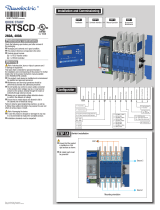
OTM_C
Operation
0I 0 0II
Switch I
Close
Open
Close
Open
Switch II
Switch I
Switch II
Operation
IIII
Close
Open
Close
Open
ON
OFF
ON
ON
ON
ON
A06102
ON
ON
OFF
OTM_CF
Switch I
Switch II
Close
Open
Close
Open
0I 0 0II
Operation
OTM_CL

4 l 1SCC303002M0206 l ABB Installation and operating instructions, 34OTM_C rev. F
1. Introduction
1. Introduction
This manual describes the installation and the basic operation of the motorized change-over
and transfer switches, types OTM_C. The instructive part is followed by a section on available
accessories.
1.1 Use of symbols
Hazardous voltage: warns about a situation where a hazardous voltage may cause
physical injury to a person or damage to equipment.
General warning: warns about a situation where something other than electrical
equipment may cause physical injury to a person or damage to equipment.
Caution: provides important information or warns about a situation that may
have a detrimental effect on equipment.
Information: provides important information about the equipment.
1.2 Explanations of abbreviations and terms
OTM_C: Motorized change-over switch, the type name
OME_: Motor operator, the type name
OT_C: Change-over switch, the type name
OZXB_ and OZXA_: Terminal clamp sets, the type name, accessories
OTZC_: Bridging bars, the type name, accessories
OTS_: Terminal shrouds, the type name, accessories
OA_: Auxiliary contacts, the type name, accessories
ODPS_: Dual power source, the type name, accessories

1SCC303002M0206 l ABB Installation and operating instructions, 34OTM_C rev. F l 5
2. Product overview
2. Product overview
Motorized change-over switches (type OTM_C) are suitable for remote control. You can operate the
motorized change-over switches either electrically by using the motor operator or manually by using
the handle. The operation, either electrical or manual, can be chosen by the selector switch “Motor/
Manual” on the motor operator. Motorized change-over switches consist of the change-over switch
and the motor operator.
Figure 2.1 Motorized change-over switch (type OTM_C)
1 Change-over switch
2 Motor operator
3 Switch panel, the operating mechanism
4 Handle for manual operation, double grip handle in sizes OTM1000-3200_C
5 Motor/Manual selection
6 Terminals for motor operator voltage supply
7 Terminals for push-buttons
8 Fuse (F1) of motor operator
9 Locking latch for releasing the handle and locking electrical operation
10 Locking clip for locking manual operation
11 Terminals for locking state information
12 Place for auxiliary contacts
II
M
M
Man.
Man.
M
M
Man.
Man.
A04120
8
6
4
9
7
10
5
3
1
12
11
I
4
10
2

6 l 1SCC303002M0206 l ABB Installation and operating instructions, 34OTM_C rev. F
A04136
II
I
M
M
M
an.
M
an.
M
M
Man.
Man.
2
1
3. Quick start
3. Quick start
This is a quick guide only meant for those who need a reminder of how to operate the unit. For more
detailed instructions, see chapter 6.
3.1 Operating the motorized change-over switch electrically;
remote control
To operate the motorized change-over switch electrically:
1. Remove the handle from the switch panel. You can remove the handle in all
positions (I, 0, II).
2. Turn the Motor/Manual selector to the Motor (M) position to enable electrical operation.
Figure 3.1 Operating the motorized change-over switch electrically; remote control
3.1.1 Locking electrical operation
To disable electrical operation, lock the locking latch with a padlock. After the locking latch has been
locked, the motorized change-over switch cannot be operated electrically. You can lock electrical
operation in all positions (I, 0, II).
Figure 3.2 Locking electrical operation
II
I
M
M
M
an.
M
an.
M
M
Man.
M
an.
A04122
M
M
Man.
Man.

1SCC303002M0206 l ABB Installation and operating instructions, 34OTM_C rev. F l 7
II
I
M
M
Man.
Man.
A04123
M
M
Man.
Man.
CLICK !
1
2
3. Quick start
3.2 Operating the motorized change-over switch manually;
local operation
To operate the motorized change-over switch manually:
1. Turn the Motor/Manual selector to the Manual (Man.) position to enable manual operation and to
prevent electrical operation.
2. Attach the handle to the switch panel. You can attach the handle in all positions
(I, 0, II).
Figure 3.3 Operating the motorized change-over switch manually
To disable the manual (and at the same time also electrical) operation, lift up the locking clip to
position 0 and attach the padlock to the handle.
Figure 3.4 Locking the manual operation
II
I
M
M
Man.
Man.
M
M
Man.
Man.
A04137

8 l 1SCC303002M0206 l ABB Installation and operating instructions, 34OTM_C rev. F
M
M
Man.
Man.
M
M
M
an.
M
an.
OMD
A04126
I
OMD
D
4. Installation
4.1 Mounting the motorized change-over switch
Figure 4.1 An example of using protection against direct contact
Use protection against direct contact.
4. Installation

1SCC303002M0206 l ABB Installation and operating instructions, 34OTM_C rev. F l 9
Figure 4.2 Motorized change-over switches, drilling hole distances / screw-mounting, [mm/in]
4. Installation
II
M
M
M
an.
M
an.
M
M
Man.
Man.
A2
A1
A04127
A1
455
180180
390
A2
390/15.35
180/7.09
455/17.91
180/7.09
U3 U4
OTM600_C_M
E4E3
OTM630-800_C_M
A1
349
142142
305
A2
335/13.19
142/5.59
389/15.31
142/5.59
U3 U4
OTM400_C_M
E4E3
OTM315-400_C_M
A1
293
116116
258
A2
282
116
325
116
E3 E4
OTM160-250_WC_M
E4E3
OTM160-250_C_M
282/11.10
116/4.57
325/12.80
116/4.57
U3 U4
OTM200_C_M
I
A1
740,5
230230
614,5
A2
E4E3
OTM2000-2500_C_M
A1
556,5
230230
476,5
A2
476,5
230
556,5
230
E3 E4
OTM1600_WC_M
E4E3
OTM1000-1250_C_M
476,5/18.77
230/9.06
556,5/21.92
230/9.06
U3 U4
OTM800-1200_C_M
OTM600-800E_C_OTM160-250_C_
OTM315_400_C_
M6M5
OTM800-1200U_C_
OTM1000-2500_C_
M10
3,5...4Nm 31...35.4 lb.in
A1
801,5
250250
661,5
A2
E4E3
OTM3200-4000_C_M
OTM3200_C_

10 l 1SCC303002M0206 l ABB Installation and operating instructions, 34OTM_C rev. F
4.2 Dimensional drawings
Figure 4.3 OTM160-250E_C_M
Figure 4.4 OTM160-250E_WC_M
4. Installation
mm
mm
M00111 / OTM160-250E_C_M D
9,0
134,5
127
A2
20
65
A1
130
162 A
B
25
122
130
150
87,5
3
23
160
48,5
72
25
37
20
83
65
OTM160-250_C_M
E3 E4
A
A1
A2
B
14
100
E2
35
116
223
238
35
116
258
273
35
116
293
308
66
9,0
134,5
127
65
A2
20
A1
130
A
B
25
170
122
150
130
87,5
3
23
160
25
83
65
OTM160-250_WC_M
E3 E4
A
A1
A2
B
14
M00115 / OTM160-250E_WC_M D
37
20
48,5 72
100
170
E2
43
116
239
254
43
116
282
297
43
116
325
340
66

1SCC303002M0206 l ABB Installation and operating instructions, 34OTM_C rev. F l 11
Figure 4.5 OTM200U_C_M
Figure 4.6 OTM315-400E_C_M
4. Installation
mm
in
mm
M00113 / OTM315-400E_C_M E
146
95
A2
25
A1
156
A
B
OTM315-400_C_M
E3
E4
A
A1
A2
B
11
160
150
31,25
185,25
456
25
87
192
43
32,5
20,5
126
95
17
120
185
E2
44
142
261
280
44
142
305
323
44
142
349
367
137,25
81
9,0
0.35
134,5
5.30
127
5.00
65
2.56
A2
20
0.79
A1
130
5.12
A
B
25
0.98
170
6.69
122
4.80
150
5.91
130
5.12
87,5
3.44
23
0.91
3
0.12
160
6.30
25
0.98
83/35,5
3.27/1.40
65
2.56
OTM200_C_M
U3
U
4
A
A1
A2
B
14
0.55
M00112 / OTM200U_C_M D
37
1.46
20
0.79
48,5
19.09
72
2.83
100
3.94
170
6.69
U2
43 / 1.69
116 / 4.57
239 / 9.40
254 / 10
43 / 1.69
116 / 4.57
282 / 11.10
297 / 11.69
43 / 1.69
116 / 4.57
325 / 12.80
340 / 13.39
66
2.6

12 l 1SCC303002M0206 l ABB Installation and operating instructions, 34OTM_C rev. F
Figure 4.8 OTM400U_C_M
Figure 4.7 OTM315-400E_WC_M
4. Installation
mm
in
mm
M00114 / OTM400U_C_M E
137,25
5.40
A2
95
3.74
25
0.98
A1
156
6.14
120
4.72
A
B
OTM400_C_M
U3
U4
A
A1
A2
B
11
0.43
220
8.66
160
6.30
150
5.91
31,25
1.23
195,25
7.69
4
0.16
56
2.20
25/
0.98
87
3.43
192
7.56
43
1.69
20,5
0.81
32,5
1.28
126 / 51,5
4.96 / 2.03
95
3.74
17
0.67
185
7.28
U2
54 / 2.13
142 / 5.59
281 / 11.06
299 / 11.77
54 / 2.13
142 / 5.59
335 / 13.19
353 / 13.90
54 / 2.13
142 / 5.59
389 / 15.31
407 / 16.02
146
5.75
81
3.19
M00116 / OTM315-400E3-4WCM B
137,25
A2
95
25
A1
156
120
A
B
OTM 315-400_WC_M
E3
E4
A
54 54
A1
142
142
A2
334,5
388,5
B
353
407
11
220
160
150
31,25
195,25
456
87
192
43
20,5
32,5
126/51,5
95
17
185

1SCC303002M0206 l ABB Installation and operating instructions, 34OTM_C rev. F l 13
145
17
200
160
A1
147,5
A2
198
210
250
212,5
A
B
47,5
39
45
132,6
110,5
5
64,1
256
A
A1
A2
B
E2 E3 E4
65 65 65
180 180
180
325
390
455
346
411
476
OTM630-800E_C_M
138,6
61,5
13,5
M00140/OTM630-800E02-04C_M B
158
43
20,5
200
A1
160
6.3 0
147,5
A2
198
210
250
212,5
A
B
47,5
39
13,5
45
132,6
5
64,1
400
43
256
mm
in
5.81
1.54
0.53
7. 87
8.3 7
1.87
7.80
8.27
9.84
509
20.04
15.75
2.52
0.20
5.22
1.77
1.69
10.08
145
17
0.67
5.71
A
A1
A2
B
U2 U3 U4
65/2.56 65/2.56 65/2.56
180/7.09 180/7.09 180/7.09
325/12.8 390/15.35 455/17.91
346/13.62 411/16.18 476/18.74
OTM600_C_M
M00139/ OTM600U_C_M B
158
6.22
20,5
0.8
Figure 4.9 OTM630-800E_C_M
Figure 4.10 OTM600U_C_M
4. Installation
mmmm

14 l 1SCC303002M0206 l ABB Installation and operating instructions, 34OTM_C rev. F
4. Installation
Figure 4.12 OTM1600E_C_M
M
Man.
A2
186
171
200
Ø13,5
50
338
326
258
246
372
253
B
A
63
260
A1
206
400
15
19
74,5
15
136
83
296,5
75
OTM1600_C_M
A
A1
A2
B
E2
80
230
396,6
426,5
E3
80
230
476,5
506,5
E4
80
230
556,5
586,5
M00258/OTM1600E_C_M B
167
158,5
127
100
335
M
Man.
13,5
50
A2
200
186
171
260
A1
206
253
A
B
63
306
272
250
74,5 15
136
50
400
15
19
296,5
75
OTM1000-1250_C_M
A
A1
A2
B
E2
80
230
396,5
426,5
E3
80
230
476,5
506,5
E4
80
230
556,5
586,5
167
158,5
M00256/OTM1000-1250E_C_M B
80
127
100
335
Figure 4.11 OTM1000-1200E_C_M
mm
mm

1SCC303002M0206 l ABB Installation and operating instructions, 34OTM_C rev. F l 15
4. Installation
Figure 4.14 OTM2000-2500E_C_M
Figure 4.13 OTM800-1200U_C_M
mm
M
Man.
A2
186 / 7.33
171 /6.74
200
7.88
260
10.24
A1
206
8.12
253 / 9.97 A
B
63
2.48
13,5 / 0.53
50 / 1.97
372
14.65
546
21.51
338
13.32
326
12.84
258
10.16
246
9.69
OTM800-1200_C_M
A
A1
A2
B
U2
80/3.15
230/9.06
396,5/15.62
426,5/16.8
U3
80/3.15
230/9.06
476,5/18.77
506,5/19.96
U4
80/3.15
230/9.06
556,5/21.92
586,5/23.11
M00257/OTM1200U_C_M B
400
15.76
15
0.59
19
0.75
1
2
2
1
296,5
11.68
75
2.95
1
2
136 / 5.36
74,5
2.93
15
0.59
83
3.27
405
15.96
1
2
167
6.58
335
13.19
100
Ø 13,5
M
Man.
A2
200
186
171
260
A1
206
B
276
A
86
376,4
342,4
330,4
262,4
250,4
OTM2000-2500_C_M
A
A1
A2
B
E2
126
230
488,5
518,5
E3
126
230
614,5
644,5
E4
126
230
740,5
770,5
M00259/OTM2000-2500E_C_M B
296,5
206
335
136
85
74,5
15
167
158,5
400
15
19
75
100
127
mm
in

Installation and operating instructions, OTM160-2500_C
16 l 1SCC303002M0206 l ABB Installation and operating instructions, 34OTM_C rev. F
mm
Figure 4.15 OTM3200_C_M
13,5
A2
200
100
186
171
280
A1
206
258
A
B
73
284
296
364
376
410
325
61
4,8
85
63
15
191
Ø
400
15
245
141
156,5
223
429
170,5
100,5
377
424
240
M00432/OTM3200_C_M B
OTM3200_C_M
E2 E3 E4
140
250
521,5
551,5
140
250
661,5
691,5
140
250
801,5
831,5
A
A1
A2
B
4. Installation

1SCC303002M0206 l ABB Installation and operating instructions, 34OTM_C rev. F l 17
1SCC303002M0206 l ABB Installation and operating instructions, 34OTM_C rev. F l 17
4.3 Connections
4. Installation
II
I
2
A06272
1
II
I
10 mm
10 mm
50 mm
50 mm
Figure 4.16 Mounting the connections to the motorized change-over switches OTM3200_C_M

18 l 1SCC303002M0206 l ABB Installation and operating instructions, 34OTM_C rev. F
II
M
M
M
an.
M
an.
M
M
Man.
M
an.
I
A04128
1
2
4.4 Mounting positions
The recommended mounting positions for motorized change-over switches are horizontal, wall
mounted or table mounted.
Do not install the motorized change-over switches in any other position than those
described above.
4.5 Labelling
Figure 4.19 Labelling of the motorized change-over switches
4. Installation
A06103
Figure 4.18 Mounting positions

1SCC303002M0206 l ABB Installation and operating instructions, 34OTM_C rev. F l 19
5. Connecting
Only an authorised electrician may perform the electrical installation and
maintenance of motorized change-over switches. Do not attempt any installation
or maintenance actions when a motorized change-over switch is connected to the
electrical mains. Before starting work, make sure that the change-over switch is de-
energised.
5.1 Control circuit
The control voltage (output C = 24Vdc) on the control terminal is non-isolated, see
box 2 in Figure 5.1
When relay outputs are used with inductive loads (such as relays, contactors and
motors), they must be protected from voltage spikes using varistors, RC-protectors
(AC current) or DC current diodes (DC current).
Do not couple power for the control terminal. See the correct terminal for the
power supply in Figure 5.1
5. Connecting
II
M
M
Man.
Man.
M
M
Man.
Man.
I
A04129
PE
N
L
F2
C
II
I
0
A
LOAD
1
2
3
BC
-
+
11
14
12
23
24
LINE
LINE
M
PE N L
F 2
11 14 12 23 24
Do not connect to
any power supply
24 vdc
3
2
1
Figure 5.1 Motorized change-over switch terminals
1. Terminal for motor operator voltage supply
2. Control terminal for push buttons or selector switch
3. Terminal for state information of locking

20 l 1SCC303002M0206 l ABB Installation and operating instructions, 34OTM_C rev. F
A04131
II
I
M
M
M
an.
M
an.
M
M
Man.
Man.
6. Operating
6.1 Electrical operation
The motorized change-over switches are available for remote control.
To operate the motorized change-over switch electrically:
1. Release the handle from the switch panel by pressing down the locking latch under the
switch panel and pulling the handle off, see Figure 6.1.
Electrical operation is disabled if the handle is attached to the switch panel.
Never open any covers on the product. There may be dangerous external control
voltages inside the motorized change-over switch even if the voltage is turned off.
Never handle control cables when the voltage of the motorized change-over switch
or external control circuits are connected.
Exercise suffi cient caution when handling the unit.
Figure 6.1 Releasing the handle
6. Operating

1SCC303002M0206 l ABB Installation and operating instructions, 34OTM_C rev. F l 21
0
I
II
A04132
M
M
Man.
Man.
M
M
Man.
Man.
The motor operator is protected from overloading by a fuse (F1) under the motor
operator. Only use the same type of fuse that is described on the label close to
the fuse.
If a new command is given before the switch has reached the position of the
previous command, the fuse (F1) may operate.
Figure 6.3 Impulse control
6.1.1 Impulse control
When using impulse control, the change-over switch is operated by electric impulses. When you
press the control button, the change-over switch is driven to the corresponding position (I, 0, II). The
control impulse must last more than 100ms to take effect. A new command cannot be given until
the change-over switch has reached the position of the previous command. Figure 6.3 shows the
operation of the change-over switch with impulse control.
Figure 6.2 Motor/Manual selection switch in the Motor (M) position
3. Operate the motorized change-over switch with the push-buttons or selector switch via impulse
control or continuous control.
2. Turn the Motor/Manual selection switch to the Motor (M) position, see Figure 6.2.
6. Operating
Figure 6.3 Impulse control
I - position
0 - position
I+II (_CL)
II -position
I - command
II - command
0 - command
0
I+II (_CL)
0
III
>100 ms
>100 ms
>100 ms
A04130
/