
Drive Technology \ Drive Automation \ System Integration \ Services
Manual
MOVIDRIVE
®
MDX61B
Internal Synchronous Operation (ISYNC)
Edition 06/2011 19295626 / EN

SEW-EURODRIVE—Driving the world

Manual – MOVIDRIVE® MDX61B Internal Synchronous Operation (ISYNC)
3
Contents
Contents
1 Important Information......................................................................................... 4
1.1 Documentation............................................................................................ 4
1.2 Bus systems................................................................................................ 4
1.3 Operating mode "synchronous operation" .................................................. 4
1.4 Structure of the safety notes ....................................................................... 5
2 System Description............................................................................................. 6
2.1 Application fields ......................................................................................... 6
2.2 Functional description ................................................................................. 6
2.3 State machine for internal synchronous operation...................................... 8
2.4 Controlling internal synchronous operation................................................. 9
3 Project Planning................................................................................................ 10
3.1 Application examples ................................................................................ 10
3.2 Requirements............................................................................................ 12
3.3 Project planning information ..................................................................... 14
3.4 Synchronous start/stop ............................................................................. 15
4 Operating Principle and Functions ................................................................. 16
4.1 Controlling internal synchronous operation............................................... 16
4.2 Main state machine................................................................................... 16
4.3 Startup cycle mode control ....................................................................... 18
4.4 Synchronous operation ............................................................................. 25
4.5 Offset cycle type ....................................................................................... 29
4.6 Stop cycle state machine .......................................................................... 34
4.7 Virtual encoder.......................................................................................... 35
4.8 Important notes ......................................................................................... 39
4.9 Internal synchronous operation via SBus ................................................. 41
5 Startup................................................................................................................ 42
5.1 General information .................................................................................. 42
5.2 Preliminary work ....................................................................................... 42
5.3 Starting up internal synchronous operation .............................................. 43
5.4 Startup interface for internal synchronous operation ................................ 49
6 System Variables for Internal Synchronous Operation................................. 86
7IPOS
plus®
Sample Programs ............................................................................ 97
7.1 Example 1 ................................................................................................. 97
7.2 Example 2 ............................................................................................... 101
7.3 Example 3 ............................................................................................... 105
7.4 IPOS
plus®
program master inverter......................................................... 106
7.5 IPOS
plus®
program slave inverter ........................................................... 107
7.6 Header file with variable designation ...................................................... 108
Index................................................................................................................. 110

4
Manual – MOVIDRIVE® MDX61B Internal Synchronous Operation (ISYNC)
1
Documentation
Important Information
MOVIDRIVE® MDX61B Internal Synchrono us Operation (ISYNC)
1 Important Information
1.1 Documentation
• Read through this manual carefully before you commence installation and startup of
MOVIDRIVE
®
inverters with internal synchronous operation.
• This manual assumes that the user has access to and is familiar with the
MOVIDRIVE
®
documentation, in particular the MOVIDRIVE
®
system manual.
• As a prerequisite to fault-free operation and fulfillment of warranty claims, you must
adhere to the information in the documentation.
1.2 Bus systems
General safety notes for bus systems:
This communication system allows you to adapt the MOVIDRIVE
®
inverter to your
application. As with all bus systems, there is a danger of modifications to the parameters
that are not visible from outside (in relation to the inverter), which give rise to changes
in the inverter behavior. This may result in unexpected (not uncontrolled) system behav-
ior.
1.3 Operating mode "synchronous operation"
The motion controller in synchronous operation processes setpoint changes at the
master drive. Set the application module in such a way that an unintended motor start
is not possible.
The following measures increase operational safety:
• Deactivating the synchronous operation mode
– when warnings or errors occur within the sync group or when the drives are not
ready for operation
– when the sync group has been stopped
• Selecting the synchronous operation mode with querying the "ready for operation"
message and the "technology options" operating status of all drives.
• If an absolute position reference is required, arrange the individual drives in the
positioning operation mode (no offset control).
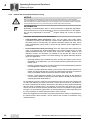
INFORMATION
• This manual does not replace the detailed operating instructions.
• Only trained personnel are allowed to perform installation and startup.
Adhere to all applicable accident prevention regulations and the
MOVIDRIVE
®
operating instructions.

Manual – MOVIDRIVE® MDX61B Internal Synchronous Operation (ISYNC)
5
1
Structure of the safety notes
Important Information
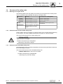
1.4 Structure of the safety notes
1.4.1 Meaning of the signal words
The following table shows the grading and meaning of the signal words for safety notes,
notes on potential risks of damage to property, and other notes.
1.4.2 Structure of the section-related safety notes
Section safety notes do not apply to a specific action, but to several actions pertaining
to one subject. The used symbols indicate either a general or a specific hazard.
This is the formal structure of a section safety note:
1.4.3 Structure of the embedded safety notes
Embedded safety notes are directly integrated in the instructions just before the descrip-
tion of the dangerous action.
This is the formal structure of an embedded safety note:
• SIGNAL WORD Nature and source of hazard.
Possible consequence(s) if disregarded.
– Measure(s) to prevent the danger.
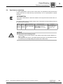
Signal word Meaning Consequences if disregarded
DANGER Imminent danger Severe or fatal injuries
WARNING Possible dangerous situation Severe or fatal injuries
CAUTION Possible dangerous situation Minor injuries
NOTICE Possible damage to property Damage to the drive system or its
environment
INFORMATION Useful information or tip: Simpli-
fies the handling of the drive
system.
SIGNAL WORD
Type and source of danger.
Possible consequence(s) if disregarded.
• Measure(s) to prevent the danger.

6
Manual – MOVIDRIVE® MDX61B Internal Synchronous Operation (ISYNC)
2
Application fields
System Description
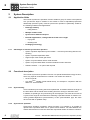
2 System Description
2.1 Application fields
The internal synchronous operation function enables a group of motors to be operated
at a synchronous angle in relation to one another or with an adjustable proportional
relationship (electronic gear). Internal synchronous operation is particularly suited for
the following industries and applications:
• Beverage industry
– Filling stations
• Multiple column hoists
• Synchronous material transport
• Extruder applications, cutting material off the roll to length
– Flying saw
– Rotating knife
• Packaging technology
2.1.1 Advantages of internal synchronous operation
• Option of position-dependent synchronization → smooth synchronizing without over-
shooting
• Option of position-dependent offset
• Signed input of the master gear factor
• Option of synchronization with a virtual encoder
• Option of synchronized SBus connection between master and slave
• Software solution → no option card required
2.2 Functional description
The internal synchronous operation function is a special firmware/technology function,
which only expects increments from a master. The master can either be
• the X14 input or
•any IPOS
plus®
variable (virtual master drive), for example in conjunction with the
SBus or a virtual encoder.
2.2.1 Synchronizing
Time-controlled synchronizing has been implemented. A variation between the angle of
the slave drive and the master drive resulting from free running is reduced to zero.
In addition, a special type of synchronizing can be employed. The slave drive moves at
a synchronous angle to the master drive following a specified number of master incre-
ments (position-dependent synchronization). In this synchronization type, the slave
drive moves with a quadratic ramp.
2.2.2 Synchronous operation
Synchronous operation comprises various functions. For example, it is possible to
operate with a specified offset over a specific travel distance. An offset between the
master and slave drive comes into effect after a specified number of master increments.
P
i
f
kVA
Hz
n
P
i
f
kVA
Hz
n

Manual – MOVIDRIVE® MDX61B Internal Synchronous Operation (ISYNC)
7
2
Functional description
System Description
2.2.3 Disengaging
Disengaging means the slave exits synchronous operation. This process can be
triggered manually by setting a system variable, or can be event-driven using an
external signal.
P
i
f
kVA
Hz
n
P
i
f
kVA
Hz
n

8
Manual – MOVIDRIVE® MDX61B Internal Synchronous Operation (ISYNC)
2
State machine for internal synchronous operation
System Description
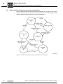
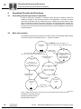
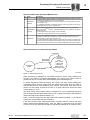
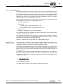
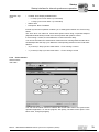
2.3 State machine for internal synchronous operation
The individual functions of internal synchronous operation are controlled using a state
machine. The state machine has the six main states shown in the following figure. See
also the chapter Operating principle and functions (page 16).
4040057355
Figure 1: Overview of the state machine for internal synchronous operation
Free mode
n-control
Z0
Synchronous
drive
Z3
Free mode
x-control
Z1
Coupling state
Z2
Engaging control or
IPOS program
Stop cycle state
Z5
Offset cycle state
Z4
Engaging control or
IPOS program
Decoupling control or
IPOS program
IPOS program
Decoupling control or
IPOS program
Offset control
or IPOS program
Automatic
transfer
Automatic
transfer
Automatic
transfer
Automatic
transfer
P
i
f
kVA
Hz
n
P
i
f
kVA
Hz
n

Manual – MOVIDRIVE® MDX61B Internal Synchronous Operation (ISYNC)
9
2
Controlling internal synchronous operation
System Description
2.3.1 Six main states
The state machine distinguishes between the six states Z0 to Z5. See also the chapter
Operating principle and functions (page 16).
• State Z0 = Free mode speed control
The slave drives moves in free-running mode with speed control. The reference to
the master drive can be stored in a difference counter.
• State Z1 = Free mode position control
The slave drive stops subject to position control and therefore does not drift out of
position. The reference to the master drive can be stored as desired.
• State Z2 = Engaging state
The slave drive is synchronized with the master drive using time or position control.
• State Z3 = Synchronous operation
The slave drive moves synchronously with the master drive.
• State Z4 = Offset
In synchronous operation, an offset can be set subject to time or position control.
• State Z5 = Disengaging state
The slave drive exits synchronous operation.
2.4 Controlling internal synchronous operation
Internal synchronous operation is controlled using IPOS
plus®
variables within the
IPOS
plus®
application program. All states can be viewed and set in a variable range from
H360 to H446, which is reserved for internal synchronous operation.
P
i
f
kVA
Hz
n
P
i
f
kVA
Hz
n

10
Manual – MOVIDRIVE® MDX61B Internal Synchronous Operation (ISYNC)
3
Application examples
Project Planning
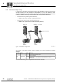
3 Project Planning
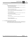
3.1 Application examples
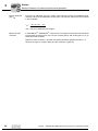
3.1.1 Master/slave operation of two drives
3.1.2 Master/slave operation of two drives with virtual encoder as master
4040685195
Figure 2: Master/slave operation
X15
X15
MDX61B...-5_3-4-0T
Basic unit
X14 X14
Master
Slave
Hiperface , Resolver
Sin/cos encoder
®
Hiperface , Resolver
Sin/cos encoder
®
4040687883
Figure 3: Master/slave operation with virtual encoder
X15
X15
MDX61B...-5_3-4-0T
MDX61B...-5_3-4-0T
X14 X14
Master = virtual encoder
Hiperface
®
, Resolver
Sin/cos encoder
Hiperface
®
, Resolver
Sin/cos encoder
Slave 1
Slave 2
IPOS-Variables
H370
...

Manual – MOVIDRIVE® MDX61B Internal Synchronous Operation (ISYNC)
11
3
Application examples
Project Planning
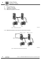
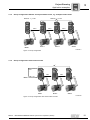
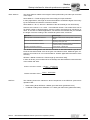
3.1.3 Group configuration: Master and equal-ranked slaves, e.g. multiple column hoist
3.1.4 Group configuration with virtual encoder
4040690571
Figure 4: Group configuration
X15X15X15
X15
MDX61B...-5_3-4-0T
SBusSBus SBus
Slave 1 Slave 2
Sin/cos
encoder
Sin/cos
encoder
Sin/cos encoder
Sin/cos
encoder
Master
Slave 3
MDX61B...-5_3-4-00
4040693259
Figure 5: Group configuration with virtual master encoder
X15X15
X15
MDX61B...-5_3-4-0T
SBus SBus
Slave 1 Slave 2
Slave 3
Sin/cos encoder
Sin/cos encoder
Sin/cos encoder
Master = virtual encoder
IPOS-Variables
H370
...

12
Manual – MOVIDRIVE® MDX61B Internal Synchronous Operation (ISYNC)
3
Requirements
Project Planning
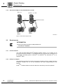
3.1.5 Slave drive subject to slip with absolute encoder
3.2 Requirements
3.2.1 PC and software
You need the SEW MOVITOOLS
®
software package version 4.10 or higher to use
internal synchronous operation. To use MOVITOOLS
®
, you must have a PC with one of
the following operating systems: Windows
®
95, Windows
®
98, Windows NT
®
4.0 or
Windows
®
2000.
3.2.2 IPOS
plus®
compiler
The application program for internal synchronous operation must be created using the
IPOS
plus®
compiler. Do not use the assembler (on-screen programming) for this
purpose.
IPOS
plus®
variables H360 to H450 are defined for internal synchronous operation.
4040695947
Figure 6: Slave drive subject to slip
X15X15
MDX61B...-5_3-4-0T
Basic unit
X14
Synchronous encoder
SBus
Slave 1
Sin/cos encoder
Sin/cos encoder
Master
INFORMATION
Internal synchronous operation is not possible with
•MOVIDRIVE
®
MDX60B

Manual – MOVIDRIVE® MDX61B Internal Synchronous Operation (ISYNC)
13
3
Requirements
Project Planning
3.2.3 Inverters
• The MOVIDRIVE
®
MDX61B...-5_3-4-0T application version already includes the
technology function for internal synchronous operation.
• Internal synchronous operation has been implemented for MOVIDRIVE
®
MDX61B
and places the following requirements on the drive system:
– Encoder feedback
– Operation modes "CFC", "SERVO" or "VFC-n control" with master/slave connec-
tion via X14-X14
• Only parameter set 1 is available; parameter set 2 cannot be used.
• The DRS11 synchronous operation card is not supported and therefore cannot be
used.
3.2.4 Motors and encoders
• For operation on MOVIDRIVE
®
MDX61B:
– CT/CV asynchronous servomotors, high-resolution sin/cos encoder installed as
standard, or Hiperface
®
encoder.
– DR/DT/DV series AC motors with incremental encoder option, preferably high-
resolution sin/cos encoder or Hiperface
®
encoder
– DS/CM synchronous servomotors, resolver (installed as standard) or Hiperface
®
encoder
High-resolution speed measurement is required for optimum operation of internal
synchronous operation. The encoders installed as standard on CT/CV and DS/CM
motors fulfill these requirements. If you use DT/DV/D motors, we recommend using
Hiperface
®
encoders or high-resolution sin/cos encoders ES1S, ES2S or EV1S.

14
Manual – MOVIDRIVE® MDX61B Internal Synchronous Operation (ISYNC)
3
Project planning information
Project Planning
3.3 Project planning information
• Do not use internal synchronous operation with systems that have a rigid mechanical
connection.
• Equip slave inverters with a braking resistor.
• During project planning, bear in mind that the slave must be able to reduce the angle
differential between itself and the master to zero at any time. For this reason, set the
maximum speed (P302) of the slave to a value greater than the maximum speed of
the master. When doing so, take the scaling factors of master and slave into account.
• Provide for a sufficient torque reserve for the slave drive.
• During the time-controlled synchronization process, the synchronization speed of the
slave drive must be faster than the maximum speed of the master drive.
• If possible, always use the same type of drives for internal synchronous operation.
• In the case of multiple column hoists, always use the same motors and the same
gear units (identical ratios).
• When drives of the same type are operating as a synchronized group (e.g. multiple
column hoist), the drive that carries the highest proportion of the load during opera-
tion must be selected as the master.
• Connect the slave motor encoder to terminal X15 (ENCODER IN) and the master
incremental encoder to terminal X14 (ENCODER IN/OUT) (→ MOVIDRIVE
®
MDX60B/61B operating instructions).
• Master is incremental encoder on terminal X14. Use an incremental encoder with the
highest possible resolution (max. 200 kHz).
• Operation with SBus → Setting up a cyclical data transfer in an IPOS
plus®
program:
– Group configuration: SBus connection between the master and all slave drives is
permitted
– SBus synchronization with transfer of the SBus synchronization ID
– Transferring the position of the master drive
• Direct cable-break monitoring is possible for X14-X14 connection via the parame-
ter encoder monitoring X14. Indirect cable-break monitoring is possible during
operation with SBus by way of the SBus timeout response (P836).

Manual – MOVIDRIVE® MDX61B Internal Synchronous Operation (ISYNC)
15
3
Synchronous start/stop
Project Planning
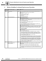
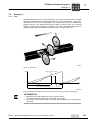
3.4 Synchronous start/stop
In certain applications, such as a two-column hoist, it is essential to make sure that the
master and slave can start and stop synchronously. This is a prerequisite for proper
operation.
The following table shows possible master-slave combinations and the settings required
for synchronous start/stop.
INFORMATION
As a result, combinations in which the master is more dynamic than the slave are not
permitted.
Master Slave Master parameters Slave parameters Comment
MDX61B MDX61B
DOØ2 = Output stage
ON
DIØ3 = Enable / rapid stop
(factory setting)
DIØ1 and DIØ2 = No function
Connect master binary
outputs DOØ2 with
slave binary input
DIØ3.
NOTICE
Strictly observe the following points:
• The brake function must be active in the master and the slave (P730 "Brake func-
tion 1" = ON).
• With asynchronous motors: The brake release time (P731) of the master must be
increased by the premagnetizing time (P323) of the slave drive.

16
Manual – MOVIDRIVE® MDX61B Internal Synchronous Operation (ISYNC)
4
Controlling internal synchronous operation
Operating Principle and Functions
4 Operating Principle and Functions
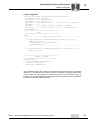
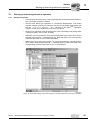
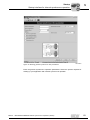
4.1 Controlling internal synchronous operation
Internal synchronous operation is controlled using IPOS
plus®
variables within the
IPOS
plus®
program, in the following referred to as "application". All states of internal
synchronous operation can be viewed and set in a variable range from H360 to H450,
which is reserved for internal synchronous operation. See also the chapter "System vari-
ables for internal synchronous operation" (page 86). All variables that are connected to
internal synchronous operation have symbolic names. These variables are shown below
in bold and italics.
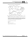
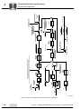
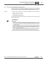
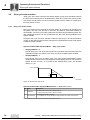
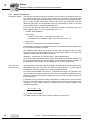
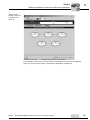
4.2 Main state machine
The following figure shows the states of the main machine and possible state changes
of internal synchronous operation (H427 → SynchronousState).
4044000907
Figure 7: Main state machine of internal synchronous operation with sub-state machines
[1] Startup cycle state machine
[2] Stop cycle state machine
[3] Offset state machine
[3]
[2]
[3]
[2]
[1][1][1][1][1]
[1]
[2]
Free mode
n-control
Z0
Synchronous
drive Z3
Free mode
x-control
Z1
Coupling state
Z2
H411.12 = 0:
time-controlled synch.
H411.12 = 1:
position-dependent synch.
Coupling control or
IPOS program
Stop cycle state/decoupling
Z5
H401.0 = 0: n-control
H401.0 = 1: x-control
Offset cycle state
Z4
H361.12 = 0: time-
controlled offset processing
H361.12 = 1:
position-dependent
offset processing
Coupling control or
IPOS program
H411.12=0: H434 Drag Distance = 0
H411.12=1: H414 Counter > H417 Master Length
Disengaging control or
IPOS program
H401.0 = 0
H401.0=1
IPOS program
Decoupling control or
IPOS program
H361.12=0: H434 Lag Distance = 0
H361.12=1: H364 Counter > H366 Master Length
Offset control
or IPOS program

Manual – MOVIDRIVE® MDX61B Internal Synchronous Operation (ISYNC)
17
4
Main state machine
Operating Principle and Functions
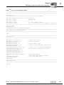
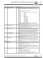
4.2.1 Six main states
The state machine distinguishes between six states (Z0 to Z5). These states are stored
in the IPOS
plus®
variable H427 SynchronousState. See also the chapter "System vari-
ables for internal synchronous operation" (page 86).
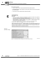
Additional func-
tions with H426
Additional functions can be selected using the bits of the H426 SynchronousMode-
Control IPOS
plus®
variable. See also the chapter "System variables for internal syn-
chronous operation" (page 86).
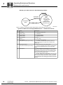
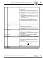
State H427 Description
SynchronousState = 0
Free-running mode n-control
The slave drive can be moved with speed control at the speed
entered in H439 SpeedFreeMode.
SynchronousState = 1
Free-running mode x-control
The slave drive is held in its current position.
SynchronousState = 2
Engaging phase
Synchronization takes place subject to time or position control
depending on bit 12 in H411 StartupCycleModeControl.
SynchronousState = 3
"Hard" synchronous operation
The slave drive follows the master drive at the same angle.
SynchronousState = 4
Offset
The offset is set subject to time or position control depending on bit
12 in H361 OffsetCycleModeControl.
SynchronousState = 5
Disengaging phase
The slave drive is decoupled with the t11 ramp (P130).
Bit Name Description
0PosTrim
= 0: Deactivated
= 1: During position control in free running mode (main state 1); causes the slave
drive to move to TargetPos (H492) without ramp. This setting should therefore
only be used for position corrections.
1 LagError
= 0: State 3, operating mode not equal to positioning, ramp type not equal to
internal synchronous operation → Lag error monitoring.
= 1: State 3, operating mode not equal to positioning, ramp type not equal to
internal synchronous operation → No lag error monitoring.
2 RegisterScale
= 0: The values of the correction mechanism are written to the difference counter
1:1.
= 1: The values are scaled with GFSlave.
3 ZeroPointMode
= 0: Precontrol is decoupled with "Set DRS zero point".
= 1: Precontrol is maintained (speed synchronization with reference to the drive),
which means the slave continues to move at the same speed as the master.
4 State Change = 0: State Change enabled
= 1: State Change disabled

18
Manual – MOVIDRIVE® MDX61B Internal Synchronous Operation (ISYNC)
4
Startup cycle mode control
Operating Principle and Functions
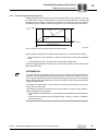
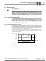
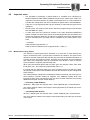
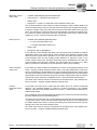
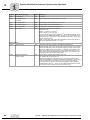
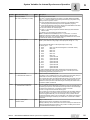
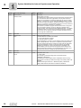
4.3 Startup cycle mode control
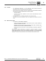
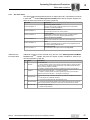
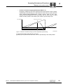
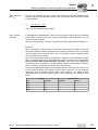
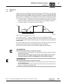
4.3.1 Time-controlled synchronizing
During time-controlled synchronizing, the existing difference of position between the
master and slave drive (64-bit counter) is compensated by accelerating or decelerating
the slave drive to the synchronization speed. The required time depends on the synchro-
nization speed, the synchronization ramp, and the lag distance (H434 LagDistance32).
The following diagram shows the speed profile of the slave drive during the entire
process (for example at constant master speed).
The synchronization speed n
sync
and the synchronization ramp a
sync
are set using
parameters P240 synchronization speed and P241 Synchronization ramp. These two
parameters are also used by the DRS11B synchronous operation card.
Synchronizing takes place in two steps:
• First, the speed of the slave drive is adjusted to the speed of the master drive by
using a specified ramp (speed synchronism).
• In the second step, any remaining angle differential (H434 LagDistance32) is
reduced to zero by accelerating or decelerating the drive (positional synchronism).
4044006667
Figure 8: Speed profile of time-controlled synchronizing
n
Master
t [s]
n
Slave
0t
x
a
synch.
P241
t
0
n
synch.
[rpm]
P240
LagDistance32 ( ) H434
eff. lag distance
at time t
Ⳏ
X
t
X
LagDistance32 ( ) H434
eff. lag distance
at time t
Ⳏ
0
t
0
INFORMATION
Observe the following points for setting the controller:
•n
max_Slave
(P302) ≥ n
sync
(P240)
The output speed of the slave drive must be equal to or greater than the output
speed of the master drive.
Observe the following during project planning:
• Provide for a sufficient torque reserve for the slave drive.

Manual – MOVIDRIVE® MDX61B Internal Synchronous Operation (ISYNC)
19
4
Startup cycle mode control
Operating Principle and Functions
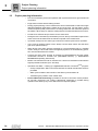
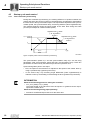
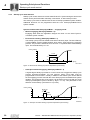
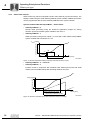
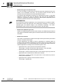
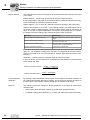
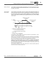
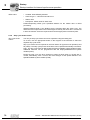
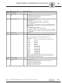
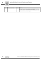
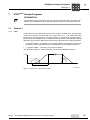
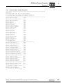
4.3.2 Position-dependent synchronizing
Position-dependent synchronizing means that the slave drive only moves in sync with
the master drive once the master drive has covered a specified distance. The specified
distance must be stored in increments in relation to the master in the H417 Startup-
CycleMasterLength variable. Observe that the slave drive must start with speed zero.
Synchronization takes place as follows (with reference to a constant master speed):
• in the range 0% to 20%, and 80% to 100%: the slave drive moves with a quadratic
ramp
• in the range 20% to 80%: the slave drive moves with a linear ramp
After the engaging distance, the slave has covered half the distance of the master (with
reference to the drive).
4044009355
Figure 9: Speed profile for position-dependent synchronization
0
n
Master
[1/min]
x
Master
[1/min]
n
Slave
20% 60% 20%
StartupCycleMasterLength
H417 (Inc.)
INFORMATION
A control element was added to prevent the loss of master increments during the
transition from position-dependent synchronizing to synchronous operation. In this
way, a specific differential increment value (H389 RegisterLoopOut) in each sampling
step is added to the 64-bit difference counter by a certain number of increments (H390
RegisterLoopDXDTOut).
The setup only takes effect in main state Z3 (synchronous operation) and can be
written directly by the user.
The following parameters should be set as given below to achieve exact results in
position-dependent synchronizing:
• H390 RegisterLoopDXDXOut = 2 The remaining travel distance can be reduced to
zero.
• H426 SynchronousModeControl.2 (RegisterScale - H426) = 1 results in multiplica-
tion with GFSlave.

20
Manual – MOVIDRIVE® MDX61B Internal Synchronous Operation (ISYNC)
4
Startup cycle mode control
Operating Principle and Functions
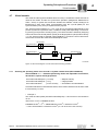
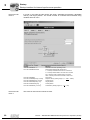
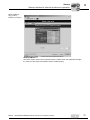
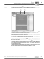
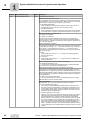
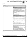
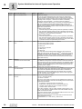
4.3.3 Startup cycle state machine
Startup cycle control reacts in the main states Z0 and Z1. Synchronizing the slave to the
master can be performed either manually, event-driven, or with interrupt control.
The startup cycle mode is defined with the H410 StartupCycleMode system variable.
Additional functions can be programmed with the H411 StartupCycleModeControl
system variable.
System variable H410 StartupCycleMode → engaging mode:
• Manual engaging (StartupCycleMode = 0)
Engaging starts when the application assigns the value 2 to the H427 Synchro-
nousState system variable.
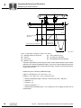
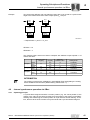
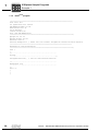
• Event-driven starting (StartupCycleMode = 1)
The startup cycle process is started event-driven via binary input. The H413 Startup-
CycleInputMask system variable defines which binary input triggers the engaging
process. The process is started as soon as level "1" is present at the defined binary
input. The terminal latency is 1 ms.
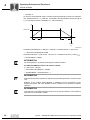
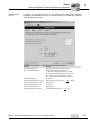
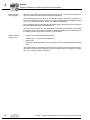
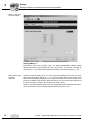
• Interrupt-controlled engaging (StartupCycleMode = 2)
A signal edge at binary input DI02 or on the C track X14:3 triggers the startup cycle
process (interrupt-controlled). For this purpose, binary input DI02 must be
programmed to "No function". A delay in relation to the master cycle can be defined
for the engaging process start with the H415 StartupCycleCounterMaxValue system
variable. The response time of the sensor can be taken into account with the H416
StartupCycleDelayDI02 system variable (1 digit = 0.1 ms). This parameter is also
effective for the startup cycle with X14:3 (C track).
4044012043
Figure 10: Event-driven starting of position-dependent synchronizing
06633AEN
Figure 11: Interrupt-controlled starting of position-dependent synchronizing
n [1/min]
Slave
x [Incr.]
Master
"1"
"0"
DI..
StartupCycleMasterLength (H417)
³ 1ms
n [1/min]
Slave
x [Incr.]
Master
"1"
"0"
DIØ2
(X14:3)
StartupCycleCounterMaxValue (H415)
StartupCycleMasterLength (H417)
150 µs
Page is loading ...
Page is loading ...
Page is loading ...
Page is loading ...
Page is loading ...
Page is loading ...
Page is loading ...
Page is loading ...
Page is loading ...
Page is loading ...
Page is loading ...
Page is loading ...
Page is loading ...
Page is loading ...
Page is loading ...
Page is loading ...
Page is loading ...
Page is loading ...
Page is loading ...
Page is loading ...
Page is loading ...
Page is loading ...
Page is loading ...
Page is loading ...
Page is loading ...
Page is loading ...
Page is loading ...
Page is loading ...
Page is loading ...
Page is loading ...
Page is loading ...
Page is loading ...
Page is loading ...
Page is loading ...
Page is loading ...
Page is loading ...
Page is loading ...
Page is loading ...
Page is loading ...
Page is loading ...
Page is loading ...
Page is loading ...
Page is loading ...
Page is loading ...
Page is loading ...
Page is loading ...
Page is loading ...
Page is loading ...
Page is loading ...
Page is loading ...
Page is loading ...
Page is loading ...
Page is loading ...
Page is loading ...
Page is loading ...
Page is loading ...
Page is loading ...
Page is loading ...
Page is loading ...
Page is loading ...
Page is loading ...
Page is loading ...
Page is loading ...
Page is loading ...
Page is loading ...
Page is loading ...
Page is loading ...
Page is loading ...
Page is loading ...
Page is loading ...
Page is loading ...
Page is loading ...
Page is loading ...
Page is loading ...
Page is loading ...
Page is loading ...
Page is loading ...
Page is loading ...
Page is loading ...
Page is loading ...
Page is loading ...
Page is loading ...
Page is loading ...
Page is loading ...
Page is loading ...
Page is loading ...
Page is loading ...
Page is loading ...
Page is loading ...
Page is loading ...
Page is loading ...
Page is loading ...
Page is loading ...
Page is loading ...
Page is loading ...
Page is loading ...
-
 1
1
-
 2
2
-
 3
3
-
 4
4
-
 5
5
-
 6
6
-
 7
7
-
 8
8
-
 9
9
-
 10
10
-
 11
11
-
 12
12
-
 13
13
-
 14
14
-
 15
15
-
 16
16
-
 17
17
-
 18
18
-
 19
19
-
 20
20
-
 21
21
-
 22
22
-
 23
23
-
 24
24
-
 25
25
-
 26
26
-
 27
27
-
 28
28
-
 29
29
-
 30
30
-
 31
31
-
 32
32
-
 33
33
-
 34
34
-
 35
35
-
 36
36
-
 37
37
-
 38
38
-
 39
39
-
 40
40
-
 41
41
-
 42
42
-
 43
43
-
 44
44
-
 45
45
-
 46
46
-
 47
47
-
 48
48
-
 49
49
-
 50
50
-
 51
51
-
 52
52
-
 53
53
-
 54
54
-
 55
55
-
 56
56
-
 57
57
-
 58
58
-
 59
59
-
 60
60
-
 61
61
-
 62
62
-
 63
63
-
 64
64
-
 65
65
-
 66
66
-
 67
67
-
 68
68
-
 69
69
-
 70
70
-
 71
71
-
 72
72
-
 73
73
-
 74
74
-
 75
75
-
 76
76
-
 77
77
-
 78
78
-
 79
79
-
 80
80
-
 81
81
-
 82
82
-
 83
83
-
 84
84
-
 85
85
-
 86
86
-
 87
87
-
 88
88
-
 89
89
-
 90
90
-
 91
91
-
 92
92
-
 93
93
-
 94
94
-
 95
95
-
 96
96
-
 97
97
-
 98
98
-
 99
99
-
 100
100
-
 101
101
-
 102
102
-
 103
103
-
 104
104
-
 105
105
-
 106
106
-
 107
107
-
 108
108
-
 109
109
-
 110
110
-
 111
111
-
 112
112
-
 113
113
-
 114
114
-
 115
115
-
 116
116


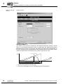
Ask a question and I''ll find the answer in the document
Finding information in a document is now easier with AI
Related papers
-
SEW MOVIDRIVE MDX61B User manual
-
-
-
-
-
SEW DFD11B User manual
-
-
-
-
Other documents
-
Zebra POS TC Product Reference Guide
-
AOpen 91.91520.F010 Datasheet
-
 halstrup-walcher PSE3**DN series User manual
-
Ryobi P241 Owner's manual
-
Eden ENCOD-USB Technical Manual
-
 Ruckus Wireless H510 Quick Setup Manual
-
Mitsubishi Electric 6-Digit Digital Switch MR-DS60 Installation guide
-
Walkera Rodeo 150 User manual
-
ABB Feather Duster User manual
-
 Antler TM/TX302 Datasheet


