SEW MOVIDRIVE MDX61B User manual

Type
User manual
Gearmotors \ Industrial Gear Units \ Drive Electronics \ Drive Automation \ Services
MOVIDRIVE
®
MDX61B
Synchronous Operation Board DRS11B
M
anual
FA361530
Edition 09/2005
11371412 / EN
SEW-EURODRIVE – Driving the world
Manual – MOVIDRIVE® MDX61B Synchronous Operation Board DRS11B
3
1 Important Notes...................................................................................................... 4
2 Introduction ............................................................................................................ 5
2.1 System description......................................................................................... 5
3 Project planning..................................................................................................... 7
3.1 Application examples..................................................................................... 7
3.2 Project planning information........................................................................... 9
3.3 Synchronous operation with cable-break monitoring of encoder connection10
3.4 Synchronous start/stop ................................................................................ 11
3.5 Synchronous operation with synchronous encoder ..................................... 12
4 Assembly and installation instructions ............................................................. 13
4.1 Installing the DRS11B option card............................................................... 13
4.2 Connection and terminal description of the DRS11B option........................ 15
4.3 Installation notes.......................................................................................... 16
4.4 MOVIDRIVE
®
MDX61B master – MOVIDRIVE
®
MDX61B slave
connection.................................................................................................... 18
4.5 Incremental encoder as master connection................................................. 19
5 Startup................................................................................................................... 20
5.1 Introduction .................................................................................................. 20
5.2 Brief description of the startup process........................................................ 21
5.3 Preliminary work........................................................................................... 22
5.4 Activating synchronous operation................................................................ 22
5.5 Testing synchronous operation with assembled drives................................ 23
5.6 Examples for the calculation of P221 and P222 .......................................... 24
6 Parameter.............................................................................................................. 27
6.1 Relationship between parameter values and output speed......................... 27
6.2 Signaling functions....................................................................................... 28
6.3 Parameter descriptions................................................................................ 30
7 Fault messages and list of faults........................................................................ 37
7.1 DRS11B synchronous operation board option............................................. 37
8 Technical Data...................................................................................................... 38
8.1 DRS11B synchronous operation board option............................................. 38
9 Index...................................................................................................................... 39
4
Manual – MOVIDRIVE® MDX61B Synchronous Operation Board DRS11B
1
Important Notes
Manual
1 Important Notes
Documentation
Read through this manual carefully before you commence installation and startup of
MOVIDRIVE
®
drive inverters with the DRS11B option.
In addition to this user manual for the DRS11B option, you should order the following
additional publications from SEW-EURODRIVE:
–MOVIDRIVE
®
MDX60/61B system manual
In this manual, cross references are marked with "->". For example, (-> Sec. X.X)
means: Further information can be found in section X.X of this manual.
A requirement of fault-free operation and fulfillment of any rights to claim under
limited warranty is that you observe the information in the documentation.
Safety and warn-
ing instructions
Always observe the safety and warning instructions contained in this publication!
This manual does not replace the detailed operating instructions!
Only specialists are allowed to perform installation and startup observing
relevant accident prevention regulations and the MOVIDRIVE
®
MDX60B/61B
operating instructions!
Electrical hazard
Possible consequences: Severe or fatal injuries.
Hazard
Possible consequences: Severe or fatal injuries.
Hazardous situation
Possible consequences: Slight or minor injuries.
Harmful situation
Possible consequences: Damage to the unit and the environ-
ment.
Tips and useful information.
Manual – MOVIDRIVE® MDX61B Synchronous Operation Board DRS11B
5
2
System description
Introduction
2 Introduction
2.1 System description
The "DRS11B synchronous operation board" enables a group of motors to be operated
at a synchronous angle in relation to one another or with an adjustable proportional
relationship (electronic gear).
The drive that specifies the position is known as the "master." This can also be an
incremental encoder. The drive that follows the position specification is known as the
"slave."
To be able to function in this way, the master and slave motors must be equipped with
encoders. MOVIDRIVE
®
MDX61B with the "DRS11B synchronous operation board"
option is used as the slave drive.
The "DRS11B synchronous operation board" option must be plugged into the expansion
slot and can only be operated in conjunction with the DEH11B or DER11B option.
The master and slave pulses counted are converted for the output side using parameter
P221/P222 (master and slave gear ratio factor). They are a measure for the pulses
counted per travel unit.
The system determines the difference of the distance information from master and slave
and stores this value in the form of incremental encoder signals in an internal differential
counter. Binary messages are set, e.g. "DRS SLAVE IN POS," "LAG ERROR," etc.
depending on the difference. The counter is evaluated differently for the various operat-
ing modes (P223) ( section 6.3).
The controller calculates the speed correction value for the slave drive to minimize the
angle differential between the master and slave. To do so, the current angle differential
is multiplied by the parameter
P220 P gain
. The result is a correction value for the slave
speed.
Master and slave run synchronously, differential value = 0 correction value = 0
Slave follows master, differential value > 0 correction value > 0, slave accelerates
Slave runs ahead of master, differential value < 0 correction value < 0, slave
decelerates
The value of the P gain (P220) is a significant factor for determining the movement
characteristics of synchronous operation control.
If the P gain is set too high, the system tends to oscillate.
If the P gain is set too low, the angle differential cannot be reduced in a transient state
(acceleration or deceleration).
The slave inverter must be equipped with a braking resistor for synchronous operation
of master and slave. The master inverter may also have to be equipped with a braking
resistor for regenerative operation, depending on the application.
6
Manual – MOVIDRIVE® MDX61B Synchronous Operation Board DRS11B
2
System description
Introduction
Block circuit
diagram for
synchronous
operation control
56502AEN
Master encoder
X42:
P230 synchronous encoder
P230 OFF or EQUAL-RANKED
P230 Synchronous encoder
P516 Encoder monitoring
P517 Pulse count monitoring
P230 CHAIN
P518 Encoder monitoring
P519 Pulse counter monitoring
P234 Master encoder resol.
P222 Slave gear ratio factor
P228 Filter feedforward DRS
P224 Slave counter P220 P gain (DRS)
P230 Synchronous encoder
P232 Maximum speed 1
Speed of
setpoint slave
EQUAL-RANKED
or CHAIN
EQUAL-RANKED
or CHAIN
Binary outputs
OFF= Slave within
position tolerance
OFF
OFF
DRS zero point
P221 Master gear ratio factor
Speed feedforward
Differentiator
Counter
Master pusles
Counter
Slave pulses
P controller
Counter LED (green)
display
Counter LED (green)
display
Lag error
Slave in position
+
-
Monitoring
Monitoring
P222
P221
X43:
Incremental encoder
simulation
X14:
Slave
synchronous encoder
X41:
Motor
synchronous encoder
X15:
1
P221
1
P221
P232
P231
Angle difference
in increments
Manual – MOVIDRIVE® MDX61B Synchronous Operation Board DRS11B
7
3
Application examples
Project planning
3 Project planning
3.1 Application examples
Example 1
Group configuration: Master and equal-ranked slaves, e.g. multiple column hoist.
Example 2
Master/slave chain: e.g. conveyor belts connected in succession
56508AEN
X15
X14
X42
Encoder feedback
Master
Speed n1
X15
X43
X42
Encoder feedback
Slave 1
Speed n2
DRS11B
DRS11B
DRS11B
X15
X43
X42
Encoder feedback
Slave 2
Speed n2
X15
Encoder feedback
Slave 3
Speed n2
56509AEN
X15
X14
X42
Encoder feedback
Master 1
Speed n1
X15
X14
X42
Encoder feedback
Master 2
Slave 1
Speed n2
DRS11B
DRS11B
DRS11B
X15
X14
X42
Encoder feedback
Master 3
Slave 2
Speed n3
X15
Encoder feedback
Master 4
Slave 3
Speed n4
8
Manual – MOVIDRIVE® MDX61B Synchronous Operation Board DRS11B
3
Application examples
Project planning
Example 3
Master/slave chain with external master incremental encoder:
Example 4
Master/slave chain with additional synchronous encoders:
56510AEN
X42
Master 1
S
p
eed n1
X15
X14
X42
Encoder feedback
Master 2
Slave 1
S
p
eed n2
DRS11B
DRS11B
DRS11B
X15
X14
X42
Encoder feedback
Master 3
Slave 2
S
p
eed n3
X15
Encoder feedback
Master 4
Slave 3
S
p
eed n4
Encoders
with external
voltage
supply
56511AEN
X15
X14
X42
Encoder feedback
Master 1
Speed n1
X41
X15
X43
X42
Encoder feedback
Master 2
Slave 1
Speed n2
DRS11B
X15
X43
X42
Encoder feedback
Master 3
Slave 2
Speed n3
X15
Encoder feedback
Master 4
Slave 3
Speed n4
Synchr.
encoder
Slave1
X41
DRS11B
Synchr.
encoder
Slave 2
X41
DRS11B
Synchr.
encoder
Slave 3
Manual – MOVIDRIVE® MDX61B Synchronous Operation Board DRS11B
9
3
Project planning information
Project planning
3.2 Project planning information
Do not use synchronous operation with systems that have a rigid mechanical
connection.
Equip slave inverters with a braking resistor.
They must activate an offset only if a previous angular offset has been processed.
During project planning for a synchronous operation application, bear in mind that the
slave must be able to reduce the angle differential between itself and the master at
any time. For this reason, set the maximum speed (P302) of the slave to a value
greater than the maximum speed of the master.
If you set the maximum speed higher than the rated motor speed in the case of AC
asynchronous motors, the full motor torque is no longer available in the field
weakening range. This can lead to lag errors (F42) in certain master/slave
combinations.
Furthermore, synchronization during the transition from free-running to synchronous
operation can be performed at maximum acceleration or using an adjustable ramp
(P24_ Synchronous operation with synchronization).
Always activate the cable-break monitoring function with synchronous operation (
Sec. 3.3).
If possible, always use the same type of drives for synchronous operation.
In the case of multiple column hoists, always use the same motors and the same
gear units (identical ratios).
In the case of group configuration (1 master and x equal-ranked slaves), a maximum
of 5 binary inputs on the slave inverter can be connected to one binary output on the
master.
If the master is stationary when the power supply is switched on and the power to the
slave is switched off and on again, the slave has the operating status "NO ENABLE."
If the master is moving when the power supply is switched on and the power to the
slave is switched off, the master issues the fault "EXTERNAL TERMINAL" (F26).
When the slave is reconnected to the power supply, the slave can detect the fault
"LAG ERROR" (F42) depending on the lag error limit set (P512).
Observe the MOVIDRIVE
®
MDX60B/61B operating instructions when connecting a
motor encoder to the EH11B / DER11B:X15 option.
Note the following during operation with the option DEH11B / DER11B:
DEH11B: The number of pulses (X14) is identical to X15 motor encoder input
DER11B: The number of pulses is always 1024 pulses per revolution
The following encoders can be connected at the inputs X41 and X42:
DC 5 V TTL encoders, encoders with RS422 signal properties, sin/cos encoders
The maximum permitted input frequency of the encoder inputs is 200 kHz
When using synchronous encoders, the ratio of the position resolutions between the
motor encoder and synchronous encoder should lie within the range
0.1 ... 10 incr./mm.
Install the encoder on the moving machine component with a positive connection
(slip-free).
Observe the following project planning instructions.
10
Manual – MOVIDRIVE® MDX61B Synchronous Operation Board DRS11B
3
Synchronous operation with cable-break monitoring of encoder connection
Project planning
If the master is an external incremental encoder, use incremental encoders with as
high a resolution as possible. However, the maximum input frequency of 200 kHz
must not be exceeded.
Parameter
P350 Change direction of rotation 1
:
When synchronous operation control is activated, P350 must be set to NO. If the
master and slave are to operate in opposite directions, the connection sequence of
the A/A
and B/B tracks at the slave input (DRS11B:X42) must be swapped over in
each pair.
The 24 V DC connection at DRS11B:X44 is mandatory in the following cases:
The encoder voltage supply is connected via option DRS11B
The binary outputs (X40:9, X40:10) or DRS11B are used.
X40:8 is used as voltage output
Encoder monitoring at X41/X42 is only possible with TTL encoders.
3.3 Synchronous operation with cable-break monitoring of encoder connection
For fault-free synchronous operation between master and slave, cable-break monitoring
is required for the connection between master DEH11B/DER11B:X14 (incremental
encoder simulation) and slave RS11B:X42. The following functions are available:
"MOTOR STANDSTILL" and "DRS MAST. STOPPED"
"/EXT. FAULT" and "/FAULT"
The only time when encoder pulses are not transferred to the slave is when the master
is at a standstill. Therefore, this status is communicated to the slave via a binary
connection. If the master does not report a standstill and the slave does not count any
encoder pulses, there is either a cable break or the master encoder is defect. As a result,
the slave switches off and communicates its status to the master via an additional
connection.
Required
connections
Program one binary output of the master to the function "MOTOR STANDSTILL."
Connect this output to a binary input on the slave, that is programmed to the function
"DRS MAST. STOPPED."
Program one binary input of the master to the function "/EXT. FAULT." Connect this
input to a binary output on the slave, that is programmed to the function "FAULT."
Additional encoder monitoring can be activated with P516 or P519 ( Sec. 6).
Manual – MOVIDRIVE® MDX61B Synchronous Operation Board DRS11B
11
3
Synchronous start/stop
Project planning
3.4 Synchronous start/stop
For MOVIDRIVE
®
synchronous operation, the following mixed mode is possible:
Master is less dynamic or as dynamic as the slave
Master is an incremental encoder
Brake function OFF:
No controller inhibit (DI00 "/CONTROLLER INHIBIT" = "1") and no ENABLE (DI03 =
"0") slave is at a standstill at speed 0 subject to speed control
No controller inhibit (DI00 "/CONTROLLER INHIBIT" = "1") and ENABLE (DI03 = "1")
slave synchronizes itself with the master position.
Brake function ON:
When both master and slave are at a standstill at speed 0, the slave brake is applied.
The following table lists the settings or cable connections for the above master/slave
combinations with regard to synchronous starting / stopping and activated cable-break
monitoring.
The master and slave(s) must be able to start / stop synchronously in both options. This
is the prerequisite for correct operation. As a result, combinations in which the master is
more dynamic than the slave are not permitted.
Master parameters Slave parameters Comment
Cable-break monitoring:
DO01 = "MOTOR STANDSTILL"
Synchronous start/stop:
DO02 = "OUTPUT STAGE ON"
Cable-break monitoring:
DI terminal = "DRS MAST. STOPPED"
Synchronous start/stop:
DI terminal = "DRS SLAVE START"
Enable slave permanently.
Binary outputs DO01 and
DO02 are no longer available
on the master.
When the brake function is activated, the slave terminal "DRS SLAVE START" must
always be programmed and wired up. This also applies when the master is only an
incremental encoder; in this case, an external controller must give the signal "DRS
SLAVE START."
When the brake function is deactivated, the position is held subject to position control
when the signal "DRS SLAVE START" is revoked or if the drive reaches the stop area
(P510).
12
Manual – MOVIDRIVE® MDX61B Synchronous Operation Board DRS11B
3
Synchronous operation with synchronous encoder
Project planning
3.5 Synchronous operation with synchronous encoder
Position measurement has to be carried out via an extra incremental encoder in all
applications in which power transmission between the motor shaft and the machine is
non-positive and thus slip is to be expected. This incremental encoder must be installed
on the moving machine component with a positive connection. In the following section,
this encoder is referred to as a synchronous encoder. The synchronous encoder is
needed to record the current position of the slave (G2). The encoder installed on the
motor shaft is still used to record the current speed (G1) of the drive.
The higher the resolution of the encoder (number of pulses counter per travel unit), the:
more accurately the slave can follow the master
more rigidly the synchronous operation control can be set (large P factor)
smaller the angle error will be during acceleration and deceleration
However, due to the calculation accuracy of the synchronous operation controller, the
ratio of the position resolutions (incr./mm) between the motor encoder and synchronous
encoder should lie in the range 0.1 ... 10. If the ratio is outside of this range, in many
cases a different synchronous encoder additional gear can be used for a more favorable
ratio.
Setting the master / slave gear ratio factor Sec. 6.3
Setting the slave encoder / slave synchronous encoder factor
A mechanical gear ratio can be set between the incremental encoder to record the
motor speed (G1) and between the incremental encoder for position measurement
(G2). This gear ratio is set with parameter P231 (factor slave encoder) / P232 (Factor
slave sync. encoder).
Equal-ranked
The signal of the master encoder at X42 is passed to the next slave via X43. In
this way, all slaves receive identical master encoder signals.
–Chain:
The signal of the synchronous encoder at X41 is passed to the following slaves
via X43. In this way, the synchronous encoder signal becomes the master
encoder signal of the following slave.
56512AEN
Figure 1: Synchronous operation with synchronous encoder; equal-ranked or chain
MOVIDRIVE
®
Slave
X15
DEH11B
DER11B
M
G2
X41
X42
DRS11B
X43
G1
Motor enc.
Gear unit
ratio i
synchr. encode
r
X42 (next slave drive)
Master encoder
Manual – MOVIDRIVE® MDX61B Synchronous Operation Board DRS11B
13
4
Installing the DRS11B option card
Assembly and installation instructions
4 Assembly and installation instructions
4.1 Installing the DRS11B option card
Before you start
The DRS11B option card must be inserted in the expansion slot.
Observe the following notes before installing or removing an option card:
Disconnect the inverter from power. Switch off the 24 V DC and the supply voltage.
Take appropriate measures to protect the option card from electrostatic charge (use
discharge strap, conductive shoes, etc.) before touching it.
Before installing the option card, remove the keypad and the front cover.
After installing the option card, replace the front cover and the keypad.
Keep the option card in its original packaging until immediately before you are ready
to install it.
Hold the option card by its edges only. Do not touch any components.
The DRS11B option card can only be installed in MOVIDRIVE
®
MDX61B sizes 1 to
6.
14
Manual – MOVIDRIVE® MDX61B Synchronous Operation Board DRS11B
4
Installing the DRS11B option card
Assembly and installation instructions
Installation and
removal of an
option card
1. Remove the retaining screws holding the card retaining bracket. Pull the card retain-
ing bracket out evenly from the slot (do not twist!).
2. Remove the retaining screws of the black cover plate on the card retaining bracket.
Remove the black cover plate.
3. Position the option card onto the retaining bracket so that the retaining screws fit into
the corresponding bores on the card retaining bracket.
4. Insert the retaining bracket with installed option card into the slot, pressing slightly so
it is seated properly. Secure the card retaining bracket with the retaining screws.
5. To remove the option card, follow the instructions in reverse order.
53001AXX
Figure 2: Installing an option card in MOVIDRIVE
®
MDX61B sizes 1 to 6
1.
3.
4.
2.
Manual – MOVIDRIVE® MDX61B Synchronous Operation Board DRS11B
15
4
Connection and terminal description of the DRS11B option
Assembly and installation instructions
4.2 Connection and terminal description of the DRS11B option
Part number
Synchronous operation board type DRS11B: 824 672 6
The DRS11B option can only be installed in connection with MOVIDRIVE
®
MDX61B
sizes 1 to 6.
The DRS11B option must be inserted in the expansion slot.
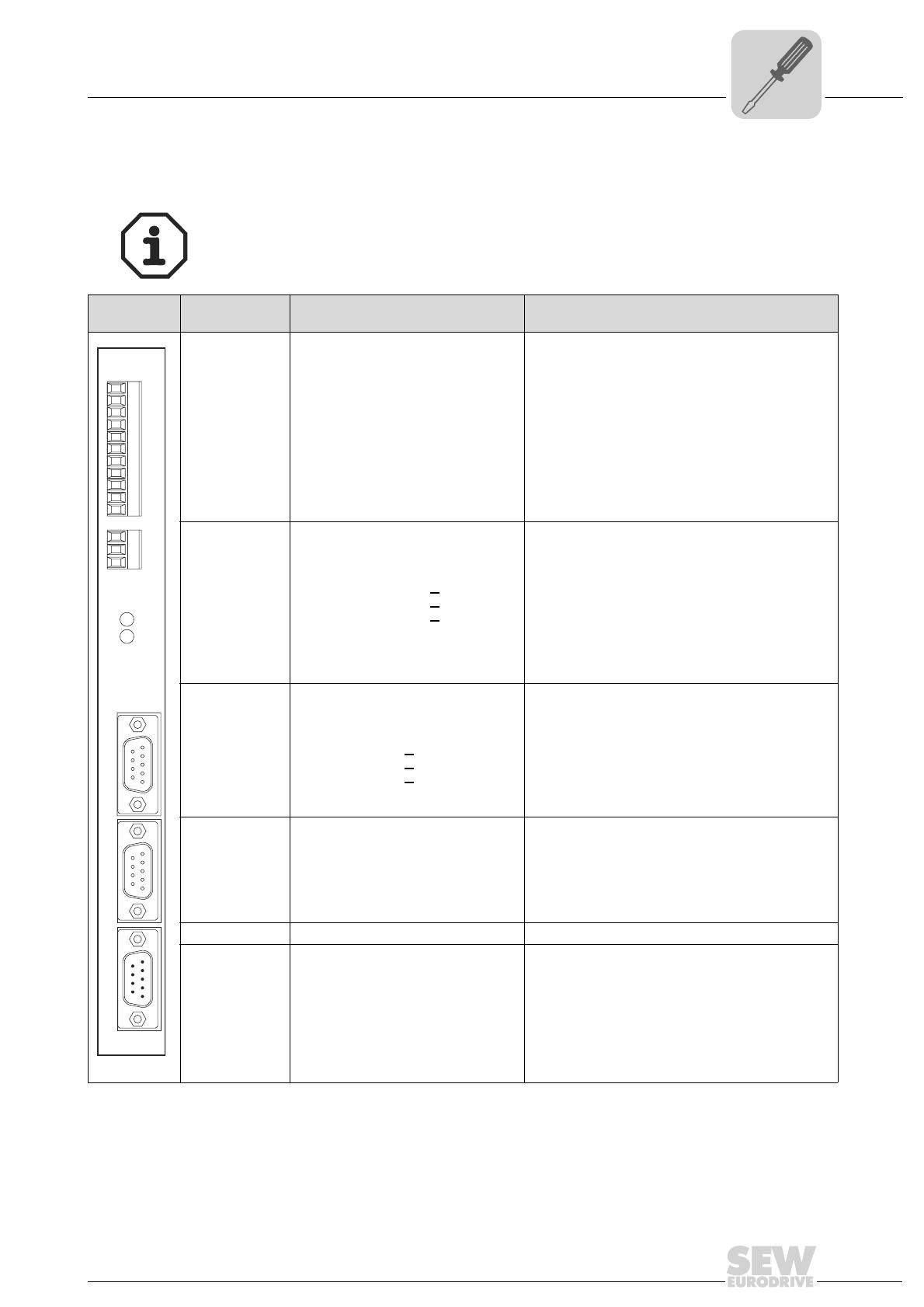
Front view of
DRS11B
Description Terminal Function
56522BXX
X40: Connec-
tion binary
inputs
X40:1 EING0: Free running mode
X40:2 EING1:Offset 1
X40:3 EING2:Offset 2
X40:4 EING3:Offset 3
X40:5 EING4: IPOS variable H477.0
X40:6 EING5: IPOS variable H477.1
X40:7 DCOM
X40:8 VO24
X40:9 AUSG0: IPOS variable H476.0
X40:10 AUSG1: IPOS variable H476.1
X4011 DGND
"0" signal = synchronous operation, "1" signal = free-
running
"0" signal= no offset, a "1" signal at EING1, EING2 or
EING3 activates offset 1, 2 or 3 (P225,P226 or P227)
The signal level of EING4 and EING5 can be read with
IPOS variable H477
Reference potential for X40:1 ... X40:6
Voltage output DC+24 V, max. DC 100 mA
Binary outputs X40:9 and X40:10: max DC 50 mA,
short-circuit proof and protected against external volt-
age. The signal level of AUSG0 and AUSG1 can be
read and set with IPOS variable H476
Reference potential for binary signals
X41: Connec-
tion
synchronous
encoder
X42:Connec-
tion master
encoder
X41/X42:1 signal track A
X41/X42:2 signal track B
X41/X42:3 signal track C
X41/X42:4 reference potential DGND
X41/X42:5 reference potential DGND
X41/X42:6 signal track A
X41/X42:7 signal track B
X41/X42:8 signal track C
X41/X42:9 VO24
Incremental encoder input for synchronous encoder
(X41) or master encoder (X42). Only use 5 V TTL
encoders, encoders with RS422 signal properties or
sin/cos encoders. Encoders with 24 V DC voltage sup-
ply can by supplied directly from X41:9 or X42:9. For
encoders with 5 V DC voltage supply, the option "5 V
encoder supply type DWI11A" must be connected
between X41/X42 and the encoder.
DC 24 V voltage supply for encoders,
max. DC 650 mA
X43: Encoder
output
X43:1 signal track A
X43:2 signal track B
X43:3 signal track C
X43:4 Not assigned.
X43:5 reference potential DGND
X43:6 signal track A
X43:7 signal track B
X43:8 signal track C
X43:9 Not assigned.
Incremental encoder output
When P230 "Synchronous encoder = OFF" or
"EQUAL-RANKED", number of pulses as at encoder
connection X42.
When P230 "Synchronous encoder = CHAIN," number
of pulses as at encoder connection X41.
X44: 24 V volt-
age input
X44:1 GND
X44:2 DC 24 V
X44:3 GND
DC 24V voltage supply
of the encoders connected to X41/X42 (max. load
X41 and X42: DC 650 mA)
of the binary outputs X40:9 and X40:10,
(max. load: DC 50 mA)
for reference output X40:8: DC 24 V,
(max. load: DC 100 mA)
LED OFF (red)
LED Sync
(green)
ON = Free-running
OFF = Synchronous operation
ON = Angle difference > value of P514
OFF = Angle difference < value of P514
DRS11B
X40X44
X41X42X43
OFF
Sync
1
5
6
9
5
1
9
6
5
1
9
6
16
Manual – MOVIDRIVE® MDX61B Synchronous Operation Board DRS11B
4
Installation notes
Assembly and installation instructions
4.3 Installation notes
Maximum permitted cable lengths:
Between master inverter and slave inverters: 10 m
Between the inverters and the encoders: 100 m
Only use shielded encoder cables with twisted pair conductors (A and A
, B and B, C
and C
) to connect:
Motor encoders and synchronous encoders
Incremental encoder simulations
Encoder input of master encoder
If necessary, connect a DC 24 V voltage supply to X44. This is used to supply
encoders connected to X41 and X42, the binary inputs X40:9 and X40:10 and volt-
age output X40:8. Note that the total current load at X41 and X42 must be 650 mA.
Note the following when connecting incremental encoders to an external supply:
Connect the reference potential of the encoder to the connection X10:2 DGND or
X10:10 DGND on the MOVIDRIVE
®
basic unit.
Enable command on slave inverter for synchronous operation (with standard default
assignment of DI01, DI02 and DI03):
DI00 (X13:1)= "1" (/Controller inhibit), DI03 (X13:4) = "1" (Enable) and
DI01 (X13:2) = "1" (CW) or DI02 (X13:3) = "1" (CCW)
Keep in mind: During synchronous operation, the direction of rotation of the slave is
determined by the direction of rotation data of the setpoint pulses passing from the
master to the slave.
If the master and slave drives turn in the same direction (CW direction for master
= CW direction for slave), the tracks are wired 1:1 ( following figure).
Part number of the prefabricated cable: 818 166 7
56525AEN
1
5
6
9
1
8
9
15
MOVIDRIVE
®
MDX61B Master
DEH11B/DER11B X14
MOVIDRIVE
®
MDX61B Slave
DRS11B X42
max. 10m
A
B
C
A
B
C
A
B
C
^
A
B
C
1
9
2
10
3
11
7
1
6
2
7
3
8
4
^
^
8
5
Changeover
Manual – MOVIDRIVE® MDX61B Synchronous Operation Board DRS11B
17
4
Installation notes
Assembly and installation instructions
If the master and slave drives turn in the opposite direction (e.g. output shafts of
gearmotors with same number of gear ratio steps are opposite each other):
Swap the connection sequence of tracks A/A
and B/B in pairs between the master
output "incremental encoder simulation" and slave input "Master encoder" ( fol-
lowing figure).
Part number of the prefabricated cable: 818 167 5
56530AEN
1
5
6
9
1
8
9
15
MOVIDRIVE
®
MDX61B Master
DEH11B/DER11B X14
MOVIDRIVE
®
MDX61B Slave
DRS11B X42
max. 10m
A
B
C
A
B
C
B
A
C
^
B
A
C
1
9
2
10
3
11
7
2
7
1
6
3
8
4
^
^
8
5
Changeover
18
Manual – MOVIDRIVE® MDX61B Synchronous Operation Board DRS11B
4
MOVIDRIVE® MDX61B master – MOVIDRIVE® MDX61B slave connection
Assembly and installation instructions
4.4 MOVIDRIVE
®
MDX61B master – MOVIDRIVE
®
MDX61B slave connection
56544CEN
DRS11B
04X44X
14X24X34X
Sync
OFF
1
5
6
9
5
1
9
6
5
1
9
6
1
2
3
1
2
3
4
5
6
7
8
9
10
11
EING0; Free-runnng
EING1; Offset 1
EING2; Offset 2
EING3; Offset 3
EING4; IPOS
plus
variable H477.0
EING5; IPOS
plus
variable H477.1
DCOM; Ref. X40:Eing0...Eing5
VO24; 100mA
AUSG0; 50mA; IPOS
plus
variable H476.0
AUSG1; 50mA; IPOS
plus
variable H476.1
DGND
GND
DC 24 V
GND
Incremental encoder input
Synchronous encoder
Incremental encoder input
Master encoder
Incremental encoder output
DI00 1
/Controller inhibit
/Brake
/Fault*
DI01 CW/stop*
CCW/stop*
2
DI02 3
DI03 Enable/stop*4
DI04 DRS MASTER STOPPED5
DI05 DRS SLAVE START6
DCOM Reference X13:DI00...DI057
VO24 DC+24 V output8
DGND Reference potential for binary signals
Reference potential for binary signals
Ref. potential for binary signals
9
ST11 RS485+
RS485-
10
ST12 11
X13:
X10:
X10:
TF1 Input
TF-/TH-/KTY+
1
DGND 2
DB00 3
DO01-C
DO02
Relay contact/ready*
Normally open contact relay
Normally closed contact relay
4
DO01-NO
DO01-NC
5
6
7
VO24 DC+24 V output8
VI24 DC+24 V input9
DGND 10
DI00 1
/Controller inhibit
DI01CW/stop*
CCW/stop*
2
DI02 3
DI03Enable/stop* 4
DI04n11/n21* 5
DI05/ext. fault 6
DCOMRef. X13:DI00...DI05 7
VO24DC+24 V 8
DGNDRef. potential for binary signals 9
ST11RS-485+
RS-485-
10
ST12 11
X13:
/Brake
Output stage ON
Ref. potential for binary signals
TF1
TF-/TH-/KTY+ input
1
DGND 2
DB00 3
DO01-C
DO02
Motor standstill
Normally closed contact relay
Normally open contact relay
4
DO01-NO
DO01-NC
5
6
7
VO24
DC+24 V
output
8
VI24
DC+24 V
input
9
DGND 10
MOVIDRIVE
®
MDX61B Master
MOVIDRIVE
®
MDX61B Slave
Cable-break monitoring
[1]
[1] Part numbers of the prefabricated cable
DEH11B/DER11B:X14
- same direction of rotation: 818 166 7
- different direction of rotation 818 167 5
DRS11B:X42
-
+
V
DC 24 V
*
Factory setting
DEH11B / DER11B
X14
simulation
Incremental encoderr-
1
9
8
15
Manual – MOVIDRIVE® MDX61B Synchronous Operation Board DRS11B
19
4
Incremental encoder as master connection
Assembly and installation instructions
4.5 Incremental encoder as master connection
56535AEN
DRS11B
X40X44
X41X42X43
OFF
Sync
1
5
6
9
5
1
9
6
5
1
9
6
1
2
3
1
2
3
4
5
6
7
8
9
10
11
Incremental enc. with
24 V DC supply
Incremental enc. with
5 V DC supply
(
MOVIDRIVE
®
MDX60B/61B operating instructions)
MOVIDRIVE
®
MDX61B Slave
1:1
EING0; Free-running
EING1; Offset 1
EING2; Offset 2
EING3; Offset 3
EING4; IPOS
plus
variable H477.0
EING5; IPOS
plus
variable H477.1
DCOM; Ref. X40:Eing0...Eing5
VO24; 100mA
AUSG0; 50mA; IPOS
plus
variable H476.0
AUSG0; 50mA; IPOS
plus
variable H476.1
DGND
GND
DC 24 V
GND
Incremental encoder input
synchronous encoder
Incremental encoder input
Master encoder
Incremental encoder output
1
5
6
9
5
1
9
6
X2
: Encoder
X1
: MOVIDRIVE
DWI11A
20
Manual – MOVIDRIVE® MDX61B Synchronous Operation Board DRS11B
5
Introduction
Startup
5Startup
5.1 Introduction
The following section describes startup of synchronous operation for a two-column hoist
( following figure).
Both drives are equipped with identical gear units with identical ratios; the rated power
of the motors and inverters are the same. For both drives, clockwise rotation on the
motor stands for upward movement on the hoist. Therefore, the prefabricated
master/slave cable (part number 818 166 7) from SEW-EURODRIVE can be used to
connect master X14 to slave X42.
Master drive:
Motor with encoder and brake.
Master inverter:
MOVIDRIVE
®
MDX61B with encoder card option, operating mode with encoder
feedback,
(e.g. VFC-n CONTROL / CFC / SERVO).
56513ADE
[1] Incremental encoder
[A]Master drive
[B]Slave drive
[B]
[A]
[1]
[1]
00
I
  • Page 1 1
  • Page 2 2
  • Page 3 3
  • Page 4 4
  • Page 5 5
  • Page 6 6
  • Page 7 7
  • Page 8 8
  • Page 9 9
  • Page 10 10
  • Page 11 11
  • Page 12 12
  • Page 13 13
  • Page 14 14
  • Page 15 15
  • Page 16 16
  • Page 17 17
  • Page 18 18
  • Page 19 19
  • Page 20 20
  • Page 21 21
  • Page 22 22
  • Page 23 23
  • Page 24 24
  • Page 25 25
  • Page 26 26
  • Page 27 27
  • Page 28 28
  • Page 29 29
  • Page 30 30
  • Page 31 31
  • Page 32 32
  • Page 33 33
  • Page 34 34
  • Page 35 35
  • Page 36 36
  • Page 37 37
  • Page 38 38
  • Page 39 39
  • Page 40 40
  • Page 41 41
  • Page 42 42
  • Page 43 43
  • Page 44 44
  • Page 45 45
  • Page 46 46
  • Page 47 47
  • Page 48 48

SEW MOVIDRIVE MDX61B User manual

Type
User manual

Ask a question and I''ll find the answer in the document

Finding information in a document is now easier with AI