
Contents
© 2018 Roland Corporation
Menu List . . . . . . . . . . . . . . . . . . . . . . . . . . . . . . . . . . . . . . . . . . . . . . . . 2
1: VIDEO INPUT . . . . . . . . . . . . . . . . . . . . . . . . . . . . . . . . . . . . . . . . 2
2: VIDEO OUTPUT . . . . . . . . . . . . . . . . . . . . . . . . . . . . . . . . . . . . . . 5
3: TRANSITION . . . . . . . . . . . . . . . . . . . . . . . . . . . . . . . . . . . . . . . . . 7
4: COMPOSITION . . . . . . . . . . . . . . . . . . . . . . . . . . . . . . . . . . . . . . 8
5: DSK . . . . . . . . . . . . . . . . . . . . . . . . . . . . . . . . . . . . . . . . . . . . . . . . 9
6: AUDIO INPUT . . . . . . . . . . . . . . . . . . . . . . . . . . . . . . . . . . . . . . . 10
7: AUDIO OUTPUT . . . . . . . . . . . . . . . . . . . . . . . . . . . . . . . . . . . . . 12
8: AUDIO FOLLOW . . . . . . . . . . . . . . . . . . . . . . . . . . . . . . . . . . . . . 14
9: AUDIO EMBEDDED . . . . . . . . . . . . . . . . . . . . . . . . . . . . . . . . . . 15
10: AUDIO AUTO MIXING . . . . . . . . . . . . . . . . . . . . . . . . . . . . . . . 16
11: MODE . . . . . . . . . . . . . . . . . . . . . . . . . . . . . . . . . . . . . . . . . . . . . 17
12: PRESET MEMORY . . . . . . . . . . . . . . . . . . . . . . . . . . . . . . . . . . . 18
13: REMOTE . . . . . . . . . . . . . . . . . . . . . . . . . . . . . . . . . . . . . . . . . . . 19
14: LAN CONTROL . . . . . . . . . . . . . . . . . . . . . . . . . . . . . . . . . . . . . 20
15: USB MEMORY . . . . . . . . . . . . . . . . . . . . . . . . . . . . . . . . . . . . . . 21
16: CAPTURE IMAGE . . . . . . . . . . . . . . . . . . . . . . . . . . . . . . . . . . . 22
17: SYSTEM . . . . . . . . . . . . . . . . . . . . . . . . . . . . . . . . . . . . . . . . . . . 23
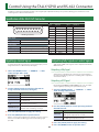
Control Using the TALLY/GPIO and RS-422 Connector . . . 25
Specication of the TALLY/GPI Connector . . . . . . . . . . . . . . . 25
Inputting a Control Signal . . . . . . . . . . . . . . . . . . . . . . . . . . . . . . 25
Outputting Tally Signals or Control Signals . . . . . . . . . . . . . . 25
Remote Control of a VISCA-compatible Video Camera . . . . 26
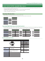
LAN/RS-232 Command Reference . . . . . . . . . . . . . . . . . . . . . . . 27
LAN Interface . . . . . . . . . . . . . . . . . . . . . . . . . . . . . . . . . . . . . . . . . 27
RS-232 Interface . . . . . . . . . . . . . . . . . . . . . . . . . . . . . . . . . . . . . . . 27
Command Format . . . . . . . . . . . . . . . . . . . . . . . . . . . . . . . . . . . . . 28
List of Commands . . . . . . . . . . . . . . . . . . . . . . . . . . . . . . . . . . . . . 29
Limitations in each Operating Mode . . . . . . . . . . . . . . . . . . . . . 32
Reference Manual

2
Menu List
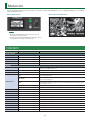
Built-in display (Menu)
MEMO
5 By turning the [VALUE] knob while pressing it, you can
change the value more greatly.
5 Pressing and holding the [VALUE] knob returns the current
menu item you’re setting to its default value.
Multi-view monitor (OSD menu)
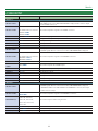
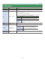
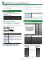
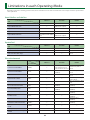
1: VIDEO INPUT
Menu item Value (bold text: default value) Explanation
SDI IN 1–SDI IN 4
INPUT STATUS (ENTER) This displays information about the incoming video (video format, size, etc.).
H FLIP OFF, ON Setting this to “ON” ips the output video horizontally.
BRIGHTNESS -64–0–63 This adjusts the brightness.
CONTRAST -64–0–63 This adjusts the contrast.
SATURATION -64–0–63 This adjusts the saturation.
HDMI IN 5
INPUT STATUS (ENTER)
This displays information about the incoming video (video format, size, presence or
absence of an HDCP signal, etc.).
FLICKER FILTER OFF, ON Setting this to “ON” reduces icker.
ZOOM 10.0–100.0–1000.0% (*1) This adjusts the zoom ratio.
SCALING TYPE
FULL
This always displays the picture expanded to full screen, irrespective of the aspect
ratio of the input video.
LETTERBOX
This enlarges or reduces the incoming video to a full-screen view while keeping the
aspect ratio unchanged.
CROP
This enlarges or reduces the incoming video so that the output picture has no
blank margins while keeping the aspect ratio unchanged. Video extending beyond
the borders is cut o.
DOT BY DOT This performs no scaling.
MANUAL Scale according to the “MANUAL SIZE H” and “MANUAL SIZE V” settings below.
MANUAL SIZE H (*2) -2000–0–2000 (*1) This adjusts the horizontal size.
MANUAL SIZE V (*2) -2000–0–2000 (*1) This adjusts the vertical size.
POSITION H -1920–0–1920 (*1) This adjusts the display position in the horizontal direction.
POSITION V -1200–0–1200 (*1) This adjusts the display position in the vertical direction.
H FLIP OFF, ON Setting this to “ON” ips the output video horizontally.
BRIGHTNESS -64–0–63 This adjusts the brightness.
CONTRAST -64–0–63 This adjusts the contrast.
SATURATION -64–0–63 This adjusts the saturation.
RED -64–0–63 This adjusts the red level.
GREEN -64–0–63 This adjusts the green level.
BLUE -64–0–63 This adjusts the blue level.
Pressing the [MENU] button makes the menu appear on the built-in display. If the HDMI OUT 3 connector’s OUTPUT ASSIGN (p. 5) is set to “MULTI-
VIEW,” the OSD menu appears.

3
Menu List
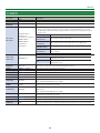
Menu item Value (bold text: default value) Explanation
EDID
INTERNAL, 800 x 600, 1024 x 768,
1200 x 800, 1366 x 768, 1280 x 1024,
1400 x 1050, 1600 x 1200, 1920 x 1200,
720p, 1080i, 1080p
This sets the input format (EDID) for the HDMI IN 5 connector.
(*1) The range of this value varies according to conditions such as the input/output format.
(*2) This is available when “SCALING TYPE” is set to “MANUAL.”
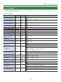
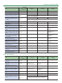
Menu item Value (bold text: default value) Explanation
HDMI/ANLG IN 6 (*3)
INPUT STATUS (ENTER)
This displays information about the incoming video (video format, size, presence
or absence of an HDCP signal, etc.).
INPUT 6 ASSIGN HDMI, RGB/COMPONENT, COMPOSITE This sets the input connector assigned to channel 6.
AUTO SAMPLING
(*4)
(EXEC)
This automatically adjusts the image quality.
* Depending on the video, adjusting the image quality might not be possible.
FLICKER FILTER OFF, ON Setting this to “ON” reduces icker.
ZOOM 10.0–100.0–1000.0% (*5) This adjusts the zoom ratio.
SCALING TYPE
FULL
This always displays the picture expanded to full screen, irrespective of the aspect
ratio of the input video.
LETTERBOX
This enlarges or reduces the incoming video to a full-screen view while keeping
the aspect ratio unchanged.
CROP
This enlarges or reduces the incoming video so that the output picture has
no blank margins while keeping the aspect ratio unchanged. Video extending
beyond the borders is cut o.
DOT BY DOT This performs no scaling.
MANUAL Scale according to the “MANUAL SIZE H” and “MANUAL SIZE V” settings below.
MANUAL SIZE H (*6) -2000–0–2000 (*5) This adjusts the horizontal size.
MANUAL SIZE V (*6) -2000–0–2000 (*5) This adjusts the vertical size.
POSITION H -1920–0–1920 (*5) This adjusts the display position in the horizontal direction.
POSITION V -1200–0–1200 (*5) This adjusts the display position in the vertical direction.
H FLIP OFF, ON Setting this to “ON” ips the output video horizontally.
BRIGHTNESS -64–0–63 This adjusts the brightness.
CONTRAST -64–0–63 This adjusts the contrast.
SATURATION -64–0–63 This adjusts the saturation.
RED -64–0–63 This adjusts the red level.
GREEN -64–0–63 This adjusts the green level.
BLUE -64–0–63 This adjusts the blue level.
FREQUENCY (*4) -128–0–127 This adjusts the input frequency.
PHASE (*4) -128–0–127 This adjusts the phase.
EDID (*7)
INTERNAL, 800 x 600, 1024 x 768,
1200 x 800, 1366 x 768, 1280 x 1024,
1400 x 1050, 1600 x 1200, 1920 x 1200,
720p (*8), 1080i (*8), 1080p (*8)
This sets the input format (EDID) of the HDMI IN 6 connector or the RGB/CMPNT/
CMPST IN connector.
(*3) The settings on the HDMI/ANLG IN 6 menu change in tandem with the assignment made using “INPUT 6 ASSIGN.” You can make separate individual settings for the
respective menu items for the HDMI IN 6 connector and the RGB/CMPNT/CMPST IN 6 connector.
(*4) This is eective when “INPUT 6 ASSIGN” is set to “RGB/COMPONENT.”
(*5) The range of this value varies according to conditions such as the input/output format.
(*6) This is available when “SCALING TYPE” is set to “MANUAL.”
(*7) This is available only when “INPUT 6 ASSIGN” is set to “HDMI” or “RGB/COMPONENT.”
(*8) This is available only when “INPUT 6 ASSIGN” is set to “HDMI.”

4
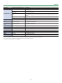
Menu List
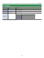
Menu item Value (bold text: default value) Explanation
STILL/BKG IN 7/8
INPUT 7 ASSIGN
STILL IMAGE 1, STILL IMAGE 2,
BACKGROUND
This assigns a still image or monochrome picture (background color) to channel
7 or 8.
STILL IMAGE 1,
STILL IMAGE 2
This selects the memory where a still image is saved
and assigns the image. A “
“ symbol is displayed for
memory where a still image is already saved.
BACKGROUND
This assigns a monochrome picture (background
color).
INPUT 8 ASSIGN
STILL IMAGE 1, STILL IMAGE 2,
BACKGROUND
BACKGROUND
COLOR
BLACK, WHITE, GRAY, RED, GREEN, BLUE,
YELLOW
This sets the background color.
* The background-color setting is shared by channels 7 and 8.

5
Menu List
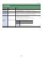
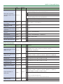
2: VIDEO OUTPUT
Menu item Value (bold text: default value) Explanation
SDI OUT 1, 2
OUTPUT STATUS —
This displays the video format.
When “HDCP” (p. 23) is set to “ON,” “HDCP MASKED” is displayed and no video is output
from the SDI OUT connectors.
OUTPUT ASSIGN
PGM/1, PVW/2, AUX/3
The default values are as follows.
SDI OUT 1: PGM/1
SDI OUT 2: PVW/2
This sets the output bus assigned to the SDI OUT connectors.
3G-SDI MAPPING LEVEL-A, LEVEL-B This sets the mapping structure for 3G-SDI output.
H FLIP OFF, ON Setting this to “ON” ips the output video horizontally.
BRIGHTNESS -64–0–63 This adjusts the brightness.
CONTRAST -64–0–63 This adjusts the contrast.
SATURATION -64–0–63 This adjusts the saturation.
HDMI OUT 1, 2
OUTPUT STATUS —
This displays information about the output video (video format and presence or absence
of an HDCP signal). When no connection is in eect, “NOT CONNECTED” is displayed.
OUTPUT ASSIGN
PGM/1, PVW/2, AUX/3
The default values are as follows.
HDMI OUT 1: PGM/1
HDMI OUT 2: PVW/2
This sets the output bus assigned to the HDMI OUT connectors.
COLOR SPACE YCC, RGB (0–255), RGB (16–235) This sets the color space.
DVI-D/HDMI
SIGNAL
DVI-D, HDMI This sets the output mode for HDMI output.
H FLIP OFF, ON Setting this to “ON” ips the output video horizontally.
BRIGHTNESS -64–0–63 This adjusts the brightness.
CONTRAST -64–0–63 This adjusts the contrast.
SATURATION -64–0–63 This adjusts the saturation.
RED -64–0–63 This adjusts the red level.
GREEN -64–0–63 This adjusts the green level.
BLUE -64–0–63 This adjusts the blue level.
HDMI OUT 3
OUTPUT STATUS –
This displays information about the output video (video format and presence or absence
of an HDCP signal). When no connection is in eect, “NOT CONNECTED” is displayed.
* If OUTPUT ASSIGN is set to “MULTI-VIEW” for the HDMI OUT 3 connector, the output
format is xed at “1080p.”
OUTPUT ASSIGN
PGM/1, PVW/2, AUX/3,
MULTI-VIEW
This sets the output bus assigned to the HDMI OUT 3 connector.
RESOLUTION (*9)
480p, 720p, 1080p, 800 x 600,
1024 x 768, 1280 x 800,
1366 x 768, 1280 x 1024,
1400 x 1050, 1600 x 1200,
1920 x 1200
This sets the output resolution using the scaler.
COLOR SPACE YCC, RGB (0–255), RGB (16–235) This sets the color space.
DVI-D/HDMI DVI-D, HDMI This sets the output mode for HDMI output.
ZOOM (*9) 10.0–100.0–1000.0% (*10) This adjusts the zoom ratio.

6
Menu List
Menu item Value (bold text: default value) Explanation
SCALING TYPE (*9)
FULL
This always displays the picture expanded to full screen, irrespective of the aspect ratio of
the input video.
LETTERBOX
This enlarges or reduces the incoming video to a full-screen view while keeping the
aspect ratio unchanged.
CROP
This enlarges or reduces the incoming video so that the output picture has no blank
margins while keeping the aspect ratio unchanged. Video extending beyond the borders
is cut o.
DOT BY DOT This performs no scaling.
MANUAL Scale according to the “MANUAL SIZE H” and “MANUAL SIZE V” settings below.
H FLIP (*9) OFF, ON Setting this to “ON” ips the output video horizontally.
MANUAL SIZE H (*9)
(*11)
-2000–0–2000 (*10) This adjusts the horizontal size.
MANUAL SIZE V (*9)
(*11)
-2000–0–2000 (*10) This adjusts the vertical size.
POSITION H (*9) -1920–0–1920 (*10) This adjusts the display position in the horizontal direction.
POSITION V (*9) -1200–0–1200 (*10) This adjusts the display position in the vertical direction.
BRIGHTNESS -64–0–63 This adjusts the brightness.
CONTRAST -64–0–63 This adjusts the contrast.
SATURATION -64–0–63 This adjusts the saturation.
RED -64–0–63 This adjusts the red level.
GREEN -64–0–63 This adjusts the green level.
BLUE -64–0–63 This adjusts the blue level.
(*9) This is valid when the HDMI OUT 3 connector’s OUTPUT ASSIGN (p. 5) is set to something other than “MULTI-VIEW.”
(*10) The range of this value varies according to conditions such as the input/output format.
(*11) Only when “SCALING TYPE” is set to “MANUAL.”

7
Menu List
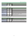
3: TRANSITION
Menu item Value (bold text: default value) Explanation
TIME 0.0–1.0–4.0 sec This sets the video transition time.
TYPE CUT, MIX, WIPE This sets the type of video transition.
MIX TYPE MIX, FAM, NAM This species the mix pattern.
WIPE TYPE
H-DOWN, H-UP, V-RIGHT, V-LEFT, H-IN, H-OUT, V-IN, V-OUT,
R-DOWN, L-DOWN, R-UP, L-UP, BLOCK, V-GRID, H-GRID,
H-DOWN s, H-UP s, V-RIGHT s, V-LEFT s, H-IN s, H-OUT s,
V-IN s, V-OUT s, R-DOWN s, L-DOWN s, R-UP s, L-UP s,
BLOCK s, V-GRID s, H-GRID s
This species the wipe pattern.
* Setting values indicated with “s” are soft edge wipe patterns.

8
Menu List
4: COMPOSITION
Menu item Value (bold text: default value) Explanation
COMPOSITION
TYPE
PinP, SPLIT This selects the type of video composition.
PinP SIZE 1/4, 1/3, 1/2
This sets the size of the inset screen. The horizontal width (and vertical height) of
the inset screen are set to 1/2, 1/3, or 1/4 the size values of the background video.
PinP POS H -45.0–45.0% (*12) This adjusts the horizontal display position of the inset screen.
PinP POS V -40.0– -25.0–40.0% (*12) This adjusts the vertical display position of the inset screen.
PinP BDR
COLOR
BLACK, WHITE, GRAY, RED, GREEN, BLUE,
YELLOW, SOFT EDGE
This sets the color of the border for the inset screen. Setting this to “SOFT EDGE”
blurs the edge.
PinP BDR
WIDTH
0–1–15 This adjusts the width of the border for the inset screen.
PinP SHAPE SQUARE, CIRCLE, HEART, DIAMOND
This species the shape of the inset screen.
SQUARE CIRCLE HEART DIAMOND
PinP ASPECT 16:9, 1:1 This sets the aspect ratio of the inset screen.
SPLIT PATTERN V-CENTER, H-CENTER, V-STRETCH, H-STRETCH
This sets the split composition pattern.
V-CENTER H-CENTER
This vertically crops the
center section of the
video.
A B
A B
A B
A B
A
B
A
B
A
B
A
B
This horizontally crops
the center section of the
video.
A B
A B
A B
A B
A
B
A
B
A
B
A
B
V-STRETCH H-STRETCH
This stretches the video
vertically.
A B
A B
A B
A B
A
B
A
B
A
B
A
B
This stretches the video
horizontally.
A B
A B
A B
A B
A
B
A
B
A
B
A
B
SPLIT PGM-CTR -25.0–0.0–25.0%
This is applied when “PATTERN” is set to “V-CENTER” or “H-CENTER.”
5 When at V-CENTER
This horizontally adjusts the display position of the video placed on the left
side.
5 When at H-CENTER
This vertically adjusts the display position of the video placed above.
SPLIT PST-CTR -25.0–0.0–25.0%
This is applied when “PATTERN” is set to “V-CENTER” or “H-CENTER.”
5 When at V-CENTER
This horizontally adjusts the display position of the video placed on the right
side.
5 When at H-CENTER
This vertically adjusts the display position of the video placed below.
(*12) The range of this value varies according to conditions such as the input/output format.

9
Menu List
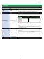
5: DSK
Menu item Value (bold text: default value) Explanation
DSK SOURCE CH
SDI IN 1–SDI IN 4, HDMI IN 5,
HDMI/ANLG IN 6, STILL/BKG IN
7, STILL/BKG IN 8
During DSK compositing, this species the channel of the overlaid logo or image.
Setting this to “STL/BKG IN 7” or “STL/BKG IN 8” performs DSK composition using a still
image saved in the unit.
KEY TYPE
LUMI-WHT, LUMI-BLK,
CRM-GRN, CRM-BLU
This species the key type (extraction color) used during DSK composition.
LUMI-WHT
This uses a brightness threshold to make white
transparent.
LUMI-BLK
This uses a brightness threshold to make black
transparent.
CRM-GRN This uses a color threshold to make green transparent.
CRM-BLU This uses a color threshold to make blue transparent.
LEVEL 0–64–255 This adjusts the degree of extraction (transparency) for the key.
GAIN 0–255 This adjusts the degree of edge blur (semi-transmissive region) for the key.
MIX LEVEL 0–255 This adjusts the key’s overall density (output level).
HUE WIDTH (*13) -128–0–127 This adjusts the hue width for the key color.
HUE FINE (*13) -128–0–127 This adjusts the center position of the hue for the key color.
SATURATION WIDTH
(*13)
-128–0–127 This adjusts the saturation width for the key color.
SATURATION FINE
(*13)
0–255 This adjusts the center position of saturation for the key color.
PGM OUT OFF, ON
This sets DSK composition on or o. When this is turned on, the results of DSK
composition are sent to nal output.
When the menu is used to turn on DSK composition, the video is composited
immediately, regardless of the length of time set for video transitions.
PVW OUT OFF, ON
Setting this to “ON” makes the DSK compositing results the preview output.
The [PVW] button functions as a shortcut for “PVW OUT.”
(*13) This is applied when “KEY TYPE” is set to “CRM-GRN” or “CRM-BLU.”

10
Menu List
6: AUDIO INPUT
Menu item
Value (bold text: default
value)
Explanation
AUDIO IN 1–AUDIO IN 4
HEAD AMP GAIN 0–64dB This adjusts head amp gain. Head amp gain adjusts analog audio.
DIGITAL GAIN -42.0–0.0–42.0dB
This adjusts digital gain. Digital gain adjusts digital audio internally converted from analog to
digital in the XS-62S.
PGM LEVEL -INF–10.0dB This adjusts the level that is output to the PGM/1 bus.
PVW LEVEL -INF–10.0dB This adjusts the level that is output to the PVW/2 bus.
PGM MUTE OFF, ON
This turns on/o the mute function for the PGM/1 bus. If this is “ON,” the audio of the PGM/1 bus
is muted (silent).
PVW MUTE OFF, ON
This turns on/o the mute function for the PVW/2 bus. If this is “ON,” the audio of the PVW/2 bus
is muted (silent).
PAN LEFT–CENTER–RIGHT This adjusts the sound position (pan).
HPF 75Hz OFF, ON
This sets the high-pass lter on or o.
Eect This cuts o unneeded low-band audio. The cuto frequency is 75 Hz.
DELAY 0.0–12.0frame
This adjusts the delay time for input audio.
Eect This outputs audio with a delay.
GATE OFF, ON
This sets gate on or o.
Eect This mutes audio that is below a specied level.
GATE THLD -80.0– -50.0–0.0dB
This sets the level used as the threshold for removing audio. Audio below the level set here is
removed.
GATE RELEASE 30–860–5000ms
This adjusts the length of time until the audio is fully attenuated after audio falls below the
threshold.
COMP OFF, ON
This sets the compressor on or o.
Eect This compresses audio that exceeds a specied level.
COMP THLD -60.0– -30.0–0.0dB
This sets the level used as the threshold at which the compressor is applied. Compression is
applied to audio that exceeds the threshold.
COMP RATIO
1.00:1, 1.12:1, 1.25:1, 1.40:1,
1.60:1, 1.80:1, 2.00:1, 2.50:1,
3.20:1, 4.00:1, 5.60:1, 8.00:1,
16.0:1, INF:1
This species the degree of compression applied to the audio.
If this is set to “1.00:1,” compression is not applied.
COMP ATTACK 0.2–1–100ms This sets the time until compression starts when audio exceeding the threshold is input.
COMP RELEASE 30–380–5000ms This adjusts the length of time until compression ends after audio falls below the threshold.
COMP AUTO G OFF, ON
This switches the auto makeup gain feature on and o.
When this is set to “ON,” the nal output volume level after applying the compressor is
automatically adjusted according to the “COMP THLD” and “COMP RATIO” settings.
The total of the “COMP MAKE UP G” setting value described below and the value calculated by
auto makeup gain becomes the nal output volume level (up to +34 dB).
COMP MAKE
UP G
-40–0.0–40dB This adjusts the nal output volume level after applying the compressor.
EQ Hi -15.0–0.0–15.0dB This boosts or attenuates the high band.
EQ Hi FREQ 1.00–10.0–20.0kHz This adjusts the center frequency when changing the tone quality in the high band.
EQ Mid -15.0–0.0–15.0dB This boosts or attenuates the middle band.
EQ Mid FREQ 20.0Hz–500Hz–20.0kHz This adjusts the center frequency when changing the tone quality in the middle band.
EQ Mid Q 0.5–1.0–16.0 This adjusts the width of the frequency band when boosting or attenuating the middle band.
EQ Lo -15.0–0.0–15.0dB This boosts or attenuates the low band.
EQ Lo FREQ 20.0–100–500Hz This adjusts the center frequency when changing the tone quality in the low band.

11
Menu List
Menu item
Value (bold text: default
value)
Explanation
AUDIO IN 5/6, SDI IN 1–SDI IN 4, HDMI IN 5, HDMI IN 6
DIGITAL GAIN -42.0–0.0–42.0dB This adjusts digital gain.
PGM LEVEL -INF–10.0dB This adjusts the level that is output to the PGM/1 bus.
PVW LEVEL -INF–10.0dB This adjusts the level that is output to the PVW/2 bus.
PGM MUTE OFF, ON
This turns on/o the mute function for the PGM/1 bus. If this is “ON,” the audio of the PGM/1 bus
is muted (silent).
PVW MUTE OFF, ON
This turns on/o the mute function for the PVW/2 bus. If this is “ON,” the audio of the PVW/2 bus
is muted (silent).
HPF 75Hz OFF, ON
This sets the high-pass lter on or o.
Eect This cuts o unneeded low-band audio. The cuto frequency is 75 Hz.
DELAY 0.0–12.0frame
This adjusts the delay time for input audio.
Eect This outputs audio with a delay.
GATE OFF, ON
This sets gate on or o.
Eect This mutes audio that is below a specied level.
GATE THLD -80.0– -50.0–0.0dB
This sets the level used as the threshold for removing audio. Audio below the level set here is
removed.
GATE RELEASE 30–860–5000ms
This adjusts the length of time until the audio is fully attenuated after audio falls below the
threshold.
COMP OFF, ON
This sets the compressor on or o.
Eect This compresses audio that exceeds a specied level.
COMP THLD -60.0– -30.0–0.0dB
This sets the level used as the threshold at which the compressor is applied. Compression is
applied to audio that exceeds the threshold.
COMP RATIO
1.00:1, 1.12:1, 1.25:1, 1.40:1,
1.60:1, 1.80:1, 2.00:1, 2.50:1,
3.20:1, 4.00:1, 5.60:1, 8.00:1,
16.0:1, INF:1
This species the degree of compression applied to the audio.
If this is set to “1.00:1,” compression is not applied.
COMP ATTACK 0.2–1–100ms This sets the time until compression starts when audio exceeding the threshold is input.
COMP RELEASE 30–380–5000ms This adjusts the length of time until compression ends after audio falls below the threshold.
COMP AUTO G OFF, ON
This switches the auto makeup gain feature on and o.
When this is set to “ON,” the nal output volume level after applying the compressor is
automatically adjusted according to the “COMP THLD” and “COMP RATIO” settings.
The total of the “COMP MAKE UP G” setting value described below and the value calculated by
auto makeup gain becomes the nal output volume level (up to +34 dB).
COMP MAKE
UP G
-40–0.0–40dB This adjusts the nal output volume level after applying the compressor.
EQ Hi -15.0–0.0–15.0dB This boosts or attenuates the high band.
EQ Hi FREQ 1.00–10.0–20.0kHz This adjusts the center frequency when changing the tone quality in the high band.
EQ Mid -15.0–0.0–15.0dB This boosts or attenuates the middle band.
EQ Mid FREQ 20.0Hz–500Hz–20.0kHz This adjusts the center frequency when changing the tone quality in the middle band.
EQ Mid Q 0.5–1.0–16.0 This adjusts the width of the frequency band when boosting or attenuating the middle band.
EQ Lo -15.0–0.0–15.0dB This boosts or attenuates the low band.
EQ Lo FREQ 20.0–100–500Hz This adjusts the center frequency when changing the tone quality in the low band.

12
Menu List
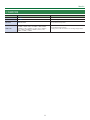
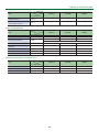
7: AUDIO OUTPUT
Menu item Value (bold text: default value) Explanation
OUTPUT ASSIGN
AUDIO OUT (XLR) PGM/1, PVW/2, AUX/3
This species the audio bus assigned to the AUDIO OUT connectors (XLR), AUDIO OUT
connectors (RCA), and PHONES connector.
PGM/1 This outputs only the audio on the PGM/1 bus.
PVW/2 This outputs only the audio on the PVW/2 bus.
AUX/3 This outputs only the audio on the AUX/3 bus.
AUDIO OUT (RCA) PGM/1, PVW/2, AUX/3
PHONES OUT PGM/1, PVW/2, AUX/3
MASTER OUTPUT
OUTPUT LEVEL -INF–10.0dB This adjusts the volume level for master out (PGM/1 bus).
OUTPUT MUTE OFF, ON This sets the Mute feature on or o. Setting this to “ON” mutes master out (PGM/1 bus).
EQ Hi -15.0–0.0–15.0dB This boosts or attenuates the high band.
EQ Hi FREQ 1.00–10.0–20.0kHz This adjusts the center frequency when changing the tone quality in the high band.
EQ Mid -15.0–0.0–15.0dB This boosts or attenuates the middle band.
EQ Mid FREQ 20.0Hz–500Hz–20.0kHz This adjusts the center frequency when changing the tone quality in the middle band.
EQ Mid Q 0.5–1.0–16.0
This adjusts the width of the frequency band when boosting or attenuating the middle
band.
EQ Lo -15.0–0.0–15.0dB This boosts or attenuates the low band.
EQ Lo FREQ 20.0–100–500Hz This adjusts the center frequency when changing the tone quality in the low band.
MB COMP OFF, ON
This switches the multi-band compressor on and o.
Eect
This applies separate compressors in the high, midrange, and low
frequency bands.
MB COMP H THLD -40.0– -20.0–0.0dB
These set the individual levels that become the thresholds for the high, midrange, and low
bands at which the compressor is applied. Compression is applied to audio that exceeds
the threshold.
MB COMP M THLD -40.0– -16.0–0.0dB
MB COMP L THLD -40.0– -20.0–0.0dB
MB COMP H RATIO
1.00:1, 1.12:1, 1.25:1, 1.40:1,
1.60:1, 1.80:1, 2.00:1, 2.50:1,
3.20:1, 4.00:1, 5.60:1, 8.00:1,
16.0:1, INF:1
The default values are as
follows.
MB COMP H RATIO: 3.20:1
MB COMP H RATIO: 2.50:1
MB COMP H RATIO: 3.20:1
These set the amount of compression applied in the high, midrange, and low bands.
If this is set to “1.00:1,” compression is not applied.
MB COMP M RATIO
MB COMP L RATIO
LIMITER OFF, ON
This sets the limiter on or o.
Eect This limits the output volume so that is does not exceed the set level.
LIMITER THLD -40.0– -6.0–0.0dB
This sets the level that becomes the threshold at which the limiter is applied. Compression
is applied to audio that exceeds the threshold. The volume level of audio that is output is
limited so as to stay to below the threshold.

13
Menu List
Menu item Value (bold text: default value) Explanation
PVW
PVW LEVEL -INF–10.0dB This adjusts the volume level for PVW/2 bus.
PVW MUTE OFF, ON This sets the Mute feature on or o. Setting this to “ON” mutes PVW/2 bus.
EQ Hi -15.0–0.0–15.0dB This boosts or attenuates the high band.
EQ Hi FREQ 1.00–10.0–20.0kHz This adjusts the center frequency when changing the tone quality in the high band.
EQ Mid -15.0–0.0–15.0dB This boosts or attenuates the middle band.
EQ Mid FREQ 20.0Hz–500Hz–20.0kHz This adjusts the center frequency when changing the tone quality in the middle band.
EQ Mid Q 0.5–1.0–16.0
This adjusts the width of the frequency band when boosting or attenuating the middle
band.
EQ Lo -15.0–0.0–15.0dB This boosts or attenuates the low band.
EQ Lo FREQ 20.0–100–500Hz This adjusts the center frequency when changing the tone quality in the low band.
MB COMP OFF, ON
This switches the multi-band compressor on and o.
Eect
This applies separate compressors in the high, midrange, and low
frequency bands.
MB COMP H THLD -40.0– -20.0–0.0dB
These set the individual levels that become the thresholds for the high, midrange, and low
bands at which the compressor is applied. Compression is applied to audio that exceeds
the threshold.
MB COMP M THLD -40.0– -16.0–0.0dB
MB COMP L THLD -40.0– -20.0–0.0dB
MB COMP H RATIO 1.00:1, 1.12:1, 1.25:1, 1.40:1,
1.60:1, 1.80:1, 2.00:1, 2.50:1,
3.20:1, 4.00:1, 5.60:1, 8.00:1,
16.0:1, INF:1
The default values are as
follows.
MB COMP H RATIO: 3.20:1
MB COMP H RATIO: 2.50:1
MB COMP H RATIO: 3.20:1
These set the amount of compression applied in the high, midrange, and low bands.
If this is set to “1.00:1,” compression is not applied.
MB COMP M RATIO
MB COMP L RATIO
LIMITER OFF, ON
This sets the limiter on or o.
Eect This limits the output volume so that is does not exceed the set level.
LIMITER THLD -40.0– -6.0–0.0dB
This sets the level that becomes the threshold at which the limiter is applied. Compression
is applied to audio that exceeds the threshold. The volume level of audio that is output is
limited so as to stay to below the threshold.
AUX
AUX LEVEL -INF–0.0–10.0dB This adjusts the volume level of audio on the AUX/3 bus.
AUX MUTE OFF, ON This sets the Mute feature on or o. Setting this to “ON” mutes the AUX/3-bus audio.
LIMITER OFF, ON
This sets the limiter on or o.
Eect This limits the output volume so that is does not exceed the set level.
THRESHOLD -40.0– -6.0–0.0dB
This sets the level that becomes the threshold at which the limiter is applied. Compression
is applied to audio that exceeds the threshold. The volume level of audio that is output is
limited so as to stay to below the threshold.

14
Menu List
8: AUDIO FOLLOW
Menu item Value (bold text: default value) Explanation
SDI IN 1–SDI IN 4
HDMI IN 5, 6
OFF, ON
This switches the Audio Follow feature on or o.
Video channels for which this is set to “ON” are automatically muted when video on
another channel is output.
AUDIO IN 1–
AUDIO IN 5/6
OFF, SDI IN 1–SDI IN 4,
HDMI IN 5, HDMI/ANLG IN 6,
STL/BKG IN 7, STL/BKG IN 8
This sets the video channel to interlink with input audio using Audio Follow. Audio from
AUDIO IN 1–AUDIO IN 5/6 is muted out for video channels other than what you specied.
When this is set to “OFF,” no video channels using Audio Follow are assigned.

15
Menu List
9: AUDIO EMBEDDED
Menu item
Value (bold text: default
value)
Explanation
AUDIO IN 1–
AUDIO IN 5/6
OFF, DRY, WET
This species the type of input audio sent to the SDI embedded-audio channels (3–8).
OFF No audio is sent.
DRY This sends the source audio with no eects applied.
WET This sends the eect-applied audio.
The audio shown below is assigned to the respective channels of SDI embedded audio.
SDI embedded-audio
channel number
Assigned audio
Channel 1 The L-channel of the bus
Channel 2 The R-channel of the bus
Channel 3 AUDIO IN 1
Channel 4 AUDIO IN 2
Channel 5 AUDIO IN 3
Channel 6 AUDIO IN 4
Channel 7 AUDIO IN 5/L
Channel 8 AUDIO IN 6/R
SDI OUT 1 AUDIO CH1–2, CH1–8 This species the embedded-audio channel that is output via the SDI OUT 1 connector.
SDI OUT 2 AUDIO CH1–2, CH1–8 This species the embedded-audio channel that is output via the SDI OUT 2 connector.

16
Menu List
10: AUDIO AUTO MIXING
Menu item
Value (bold text: default
value)
Explanation
AUTO MIXING OFF, ON This switches the Auto Mixing feature on or o.
AUDIO IN 1 SW–
AUDIO IN 4 SW
OFF, ON
This species whether Auto Mixing is applied (ON) or not applied (OFF).
AUDIO IN 5/6 SW
SDI IN 1 SW–
SDI IN 4 SW
HDMI 5 SW
HDMI 6 SW
OFF, ON
AUDIO IN 1 WT–
AUDIO IN 5/6 WT
SDI IN 1 WT–
SDI IN 4 WT
HDMI 5 WT
HDMI 6 WT
0–100% This sets the priority for volume-level distribution.

17
Menu List
11: MODE
Menu item
Value (bold text: default
value)
Explanation
MODE
PGM-PST
You can select the preset video (the video to be output next) for the PVW/2 bus, and after
checking that video, output it to the PGM/1 bus.
DISSOLVE You can select the video that you want to output, and immediately output it to the PGM/1 bus.
MATRIX You can individually select the video that is output to each bus (PGM/1, PVW/2, AUX/3 buses).

18
Menu List
12: PRESET MEMORY
Menu item
Value (bold text: default
value)
Explanation
LOAD (*14) MEMORY 1–MEMORY 8
This selects the preset memory to load. Pressing the [VALUE] knob lets you load the preset
memory.
SAVE MEMORY 1–MEMORY 8
This selects a preset memory for saving settings. Pressing the [VALUE] knob lets you save the
settings to the preset memory.
* The state of the [FREEZE] button and [PHONES] knob are not saved to any preset memory.
The [FREEZE] button is always dark at startup.
* The state of the [SW MODE] button and the settings shown below are saved as global
settings for the unit. They are not saved to preset memories.
Category Setting items saved in the unit
REMOTE
All setting items except “CAM AF” and “CAM AE”
* “CAM AF” and “CAM AE” are always set to “OFF” at startup.
LAN CONTROL All menu items
SYSTEM
All setting items except “TEST PATTERN” and “TEST TONE”
* “TEST PATTERN” and “TEST TONE” are always set to “OFF” at
startup.
DELETE MEMORY 1–MEMORY 8
This selects a preset memory to delete. Pressing the [VALUE] knob lets you delete the preset
memory.
START UP
LAST MEMORY,
MEMORY 1–MEMORY 8
This species the settings loaded at startup.
LAST MEMORY
This restores the state that was in eect immediately
before the power was turned o (Last Memory
feature). The current settings (Last Memory values) are
saved every 4 seconds, and when you exit a menu.
MEMORY 1–
MEMORY 8
These recall the settings at the selected memory
number.
MEMORY PROTECT OFF, ON
When this is set to “ON,” the preset memories are protected, and settings cannot be saved to
them.
(*14) When the [SW MODE] button is lit in blue, the cross-point (upper row) [1]–[8] buttons function as shortcuts for loading to preset memories.

19
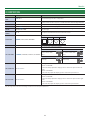
Menu List
13: REMOTE
Menu item
Value (bold text: default
value)
Explanation
RS-232 OFF, ON Setting this to “ON” makes it possible to send and receive RS-232 commands.
RS-232
BAUDRATE
9600, 38400 This sets the communication speed (bps) of the RS-232 connector.
GPI 1 TYPE–
GPI 8 TYPE
N/A, PGM CH SEL 1–
PGM CH SEL 8,
PST CH SEL 1–PST CH SEL 8,
MEMORY LOAD 1–
MEMORY LOAD 8,
DSK SRC SEL 1–
DSK SRC SEL 8
This sets the function assigned to the GPI channel.
* When a control signal is input from an external source, the assigned function is executed.
The GPI trigger is xed at the trailing edge (low: ON). For details, refer to “Inputting a Control
Signal” (p. 25).
N/A No function is assigned.
PGM CH SEL 1–
PGM CH SEL 8
This switches the nal output video.
PST CH SEL 1–
PST CH SEL 8
This switches the preset video (the video to be output next).
MEMORY LOAD 1–
MEMORY LOAD 8
This loads a preset memory.
DSK SRC SEL 1–
DSK SRC SEL 8
During DSK compositing, this switches the channel of the overlaid
logo or image.
GPO 1 TYPE–
GPO 4 TYPE
ONE SHOT, ALT
This sets the control method that is used when outputting GPO signals to an external device.
ONE SHOT
When you press a cross-point [1]–[4] button, a GPO signal is
output for 0.5 seconds.
ALT
Each time you press a cross-point [1]–[4] button, the GPO signal
output turns on/o.
RS-422
BAUDRATE
9600, 38400 This sets the communication speed (bps) of the RS-422 connector.
CAM ID CAMERA1–CAMERA7 This selects the remote camera that is operated.
CAM PAN LEFT, RIGHT This pans the remote camera. Operation occurs while you hold down the [VALUE] knob.
CAM TILT DOWN, UP This tilts the remote camera. Operation occurs while you hold down the [VALUE] knob.
PAN/TILT SPEED 1–12–24 This sets the speed of the pan and tilt operations.
CAM ZOOM IN, OUT This zooms the remote camera. Operation occurs while you hold down the [VALUE] knob.
CAM FOCUS FAR, NEAR
This focuses the remote camera. Operation occurs while you hold down the [VALUE] knob.
This is available when “CAM AF” is set to “OFF.”
CAM AF OFF, ON
This sets the auto focus function of the remote camera. The default value depends on the
settings of the camera that you’re using.
CAM BRIGHT DOWN, UP
This sets the brightness of the remote camera. Operation occurs while you hold down the
[VALUE] knob.
This is available when “CAM AE” is set to “OFF.”
CAM AE OFF, ON
This sets the auto exposure function of the remote camera. The default value depends on the
settings of the camera that you’re using.
CAM RECALL MEMORY1–MEMORY8 This recalls settings that are saved in the remote camera.
CAM STORE MEMORY1–MEMORY8 This saves settings in the remote camera.
CAM RESET (EXEC)
This resets the connection settings of the remote camera. If remote cameras are connected in a
daisy-chain, the ID of each is reassigned starting with the camera that is closest to the XS-62S.

20
Menu List
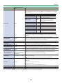
14: LAN CONTROL
Menu item
Value (bold text: default
value)
Explanation
CONFIGURE MANUALLY, USING DHCP
This sets whether the IP address and subnet mask are obtained automatically (USING DHCP) or
set manually (MANUALLY).
IP ADDRESS (*15) 192.168.2.254 This sets the IP address.
SUBNET MASK
(*15)
255.255.255.0 This sets the subnet mask.
INFORMATION (ENTER)
The LAN INFORMATION screen appears.
Indication Explanation
STATUS This displays the connection status.
IP ADDRESS This displays the IP address.
SUBNET MASK This displays the subnet mask.
MAC ADDRESS This displays the MAC address.
(*15) This is available when “CONFIGURE” is set to “MANUALLY.”
Page is loading ...
Page is loading ...
Page is loading ...
Page is loading ...
Page is loading ...
Page is loading ...
Page is loading ...
Page is loading ...
Page is loading ...
Page is loading ...
Page is loading ...
Page is loading ...
Page is loading ...
Page is loading ...
Page is loading ...
-
 1
1
-
 2
2
-
 3
3
-
 4
4
-
 5
5
-
 6
6
-
 7
7
-
 8
8
-
 9
9
-
 10
10
-
 11
11
-
 12
12
-
 13
13
-
 14
14
-
 15
15
-
 16
16
-
 17
17
-
 18
18
-
 19
19
-
 20
20
-
 21
21
-
 22
22
-
 23
23
-
 24
24
-
 25
25
-
 26
26
-
 27
27
-
 28
28
-
 29
29
-
 30
30
-
 31
31
-
 32
32
-
 33
33
-
 34
34
-
 35
35


