Roland V-60HD Reference guide

Type
Reference guide
Contents
© 2020 Roland Corporation
Menu List . . . . . . . . . . . . . . . . . . . . . . . . . . . . . . . . . . . . . . . . . . . . . . . . 2
1: VIDEO INPUT . . . . . . . . . . . . . . . . . . . . . . . . . . . . . . . . . . . . . . . . 2
2: VIDEO OUTPUT . . . . . . . . . . . . . . . . . . . . . . . . . . . . . . . . . . . . . . 4
3: TRANSITION . . . . . . . . . . . . . . . . . . . . . . . . . . . . . . . . . . . . . . . . . 4
4: COMPOSITION . . . . . . . . . . . . . . . . . . . . . . . . . . . . . . . . . . . . . . 5
5: DSK . . . . . . . . . . . . . . . . . . . . . . . . . . . . . . . . . . . . . . . . . . . . . . . . 6
6: AUDIO INPUT . . . . . . . . . . . . . . . . . . . . . . . . . . . . . . . . . . . . . . . 6
7: AUDIO OUTPUT . . . . . . . . . . . . . . . . . . . . . . . . . . . . . . . . . . . . . 9
8: AUDIO FOLLOW . . . . . . . . . . . . . . . . . . . . . . . . . . . . . . . . . . . . . 10
9: AUDIO EMBEDDED . . . . . . . . . . . . . . . . . . . . . . . . . . . . . . . . . . 10
10: AUDIO AUTO MIXING . . . . . . . . . . . . . . . . . . . . . . . . . . . . . . . 10
11: PRESET MEMORY . . . . . . . . . . . . . . . . . . . . . . . . . . . . . . . . . . . 11
12: RS-232/GPI . . . . . . . . . . . . . . . . . . . . . . . . . . . . . . . . . . . . . . . . 11
13: CAMERA CONTROL . . . . . . . . . . . . . . . . . . . . . . . . . . . . . . . . . 12
14: LAN CONTROL . . . . . . . . . . . . . . . . . . . . . . . . . . . . . . . . . . . . . 13
15: USB MEMORY . . . . . . . . . . . . . . . . . . . . . . . . . . . . . . . . . . . . . . 14
16: CAPTURE IMAGE . . . . . . . . . . . . . . . . . . . . . . . . . . . . . . . . . . . 14
17: SYSTEM . . . . . . . . . . . . . . . . . . . . . . . . . . . . . . . . . . . . . . . . . . . 15
Remotely Controlling a Camera. . . . . . . . . . . . . . . . . . . . . . . . . . 17
Network Settings on the Camera . . . . . . . . . . . . . . . . . . . . . . . 17
Controlling a Canon Camera . . . . . . . . . . . . . . . . . . . . . . . . . . . 17
Controlling a JVC/Panasonic/PTZOptics/Avonic Camera or
a Camera That Supports VISCA over IP . . . . . . . . . . . . . . . . . . 18
Control Using the TALLY/GPI Connector . . . . . . . . . . . . . . . . . 19
Specication of the TALLY/GPI Connector . . . . . . . . . . . . . . . 19
Outputting a Tally Signal . . . . . . . . . . . . . . . . . . . . . . . . . . . . . . . 19
Inputting a Control Signal . . . . . . . . . . . . . . . . . . . . . . . . . . . . . . 19
LAN/RS-232 Command Reference . . . . . . . . . . . . . . . . . . . . . . . 20
LAN Interface . . . . . . . . . . . . . . . . . . . . . . . . . . . . . . . . . . . . . . . . . 20
RS-232 Interface . . . . . . . . . . . . . . . . . . . . . . . . . . . . . . . . . . . . . . . 20
Command Format . . . . . . . . . . . . . . . . . . . . . . . . . . . . . . . . . . . . . 20
List of Commands . . . . . . . . . . . . . . . . . . . . . . . . . . . . . . . . . . . . . 21
Reference Manual
Version 3.0 and later
2
Menu List
Pressing the [MENU] button makes the menu appear on the built-in display and on the monitor connected to the MULTI-VIEW connector.
Built-in display (Menu)
MEMO
5 By turning the [VALUE] knob while pressing it, you can change
the value more greatly.
5 Pressing and holding the [VALUE] knob returns the current menu
item youre setting to its default value.
Multi-view monitor (OSD menu)
1: VIDEO INPUT
Menu item Value (bold text: default value) Explanation
SDI IN 1–4
INPUT STATUS (ENTER) This displays information about the incoming video (video format, size, etc.).
H FLIP OFF, ON Setting this to “ON” ips the output video horizontally.
BRIGHTNESS -64–0–63 This adjusts the brightness.
CONTRAST -64–0–63 This adjusts the contrast.
SATURATION -64–0–63 This adjusts the saturation.
HDMI IN 5
INPUT STATUS (ENTER)
This displays information about the incoming video (video format, size, presence or
absence of an HDCP signal, etc.).
FLICKER FILTER OFF, ON Setting this to “ON” reduces icker.
ZOOM 10.0–100.0–1000.0% (*1) This adjusts the zoom ratio.
SCALING TYPE
This sets the scaling type.
FULL
This always displays the picture expanded to full screen, irrespective of the aspect
ratio of the input video.
LETTERBOX
This enlarges or reduces the incoming video to a full-screen view while keeping the
aspect ratio unchanged.
CROP
This enlarges or reduces the incoming video so that the output picture has no blank
margins while keeping the aspect ratio unchanged. Video extending beyond the
borders is cut o.
DOT BY DOT This performs no scaling.
MANUAL Scale according to the “MANUAL SIZE H” and “MANUAL SIZE V” settings below.
MANUAL SIZE H -2000–0–2000 (*1) (*2) This adjusts the horizontal size.
MANUAL SIZE V -2000–0–2000 (*1) (*2) This adjusts the vertical size.
POSITION H -1920–0–1920 (*1) This adjusts the display position in the horizontal direction.
POSITION V -1200–0–1200 (*1) This adjusts the display position in the vertical direction.
H FLIP OFF, ON Setting this to “ON” ips the output video horizontally.
BRIGHTNESS -64–0–63 This adjusts the brightness.
CONTRAST -64–0–63 This adjusts the contrast.
SATURATION -64–0–63 This adjusts the saturation.
RED -64–0–63 This adjusts the red level.
GREEN -64–0–63 This adjusts the green level.
BLUE -64–0–63 This adjusts the blue level.
EDID
INTERNAL, 800 x 600, 1024 x 768, 1200 x 800,
1366 x 768, 1280 x 1024, 1400 x 1050,
1600 x 1200, 1920 x 1200, 720p, 1080i, 1080p
This sets the input format (EDID) for the HDMI IN 5 connector.
(*1) The range of this value varies according to conditions such as the input/output format. The values listed above are the minimum and maximum values.
(*2) This is available when “SCALING TYPE” is set to “MANUAL.
3
Menu List
Menu item Value (bold text: default value) Explanation
HDMI/RGB IN 6 (*3)
INPUT STATUS (ENTER)
This displays information about the incoming video (video format, size, presence or
absence of an HDCP signal, etc.).
INPUT 6 ASSIGN HDMI, RGB/COMPONENT This sets the input connector assigned to channel 6.
AUTO SAMPLING (EXEC) (*4)
This automatically adjusts the image quality.
* Depending on the video, adjusting the image quality might not be possible.
FLICKER FILTER OFF, ON Setting this to “ON” reduces icker.
ZOOM 10.0–100.0–1000.0% (*5) This adjusts the zoom ratio.
SCALING TYPE
This sets the scaling type.
FULL
This always displays the picture expanded to full screen, irrespective of the aspect
ratio of the input video.
LETTERBOX
This enlarges or reduces the incoming video to a full-screen view while keeping the
aspect ratio unchanged.
CROP
This enlarges or reduces the incoming video so that the output picture has no blank
margins while keeping the aspect ratio unchanged. Video extending beyond the
borders is cut o.
DOT BY DOT This performs no scaling.
MANUAL Scale according to the “MANUAL SIZE H” and “MANUAL SIZE V” settings below.
MANUAL SIZE H -2000–0–2000 (*5) (*6) This adjusts the horizontal size.
MANUAL SIZE V -2000–0–2000 (*5) (*6) This adjusts the vertical size.
POSITION H -1920–0–1920 (*5) This adjusts the display position in the horizontal direction.
POSITION V -1200–0–1200 (*5) This adjusts the display position in the vertical direction.
H FLIP OFF, ON Setting this to “ON” ips the output video horizontally.
BRIGHTNESS -64–0–63 This adjusts the brightness.
CONTRAST -64–0–63 This adjusts the contrast.
SATURATION -64–0–63 This adjusts the saturation.
RED -64–0–63 This adjusts the red level.
GREEN -64–0–63 This adjusts the green level.
BLUE -64–0–63 This adjusts the blue level.
FREQUENCY -128–0–127 (*4) This adjusts the input frequency.
PHASE -128–0–127 (*4) This adjusts the phase.
EDID
INTERNAL, 800 x 600, 1024 x 768,
1200 x 800, 1366 x 768, 1280 x 1024,
1400 x 1050, 1600 x 1200, 1920 x 1200,
720p (*7), 1080i (*7), 1080p (*7)
This sets the input format (EDID) of the HDMI IN 6 connector or RGB/COMPONENT IN
6 connector.
STILL/BKG IN 7/8
INPUT 7 ASSIGN
This assigns a still image or monochrome picture (background color) to channel 7.
STILL IMAGE 1
This selects the memory where a still image is saved and assigns the image. A
symbol is displayed for memory where a still image is already saved.
STILL IMAGE 2
BACKGROUND This assigns a monochrome picture (background color).
INPUT 8 ASSIGN
This assigns a still image or monochrome picture (background color) to channel 8.
STILL IMAGE 1
This selects the memory where a still image is saved and assigns the image. A
symbol is displayed for memory where a still image is already saved.
STILL IMAGE 2
BACKGROUND This assigns a monochrome picture (background color).
BACKGROUND COLOR
BLACK, WHITE, GRAY, RED, GREEN, BLUE,
YELLOW
This sets the background color.
* The background-color setting is shared by channels 7 and 8.
(*3) The settings on the HDMI/RGB IN 6 menu change in tandem with the assignment made using “INPUT 6 ASSIGN. You can make separate individual settings for the
respective menu items for the HDMI IN 6 connector and the RGB/COMPONENT IN 6 connector.
(*4) This is eective when “INPUT 6 ASSIGN” is set to “RGB/COMPONENT.
(*5) The range of this value varies according to conditions such as the input/output format. The values listed above are the minimum and maximum values.
(*6) This is available when “SCALING TYPE” is set to “MANUAL.
(*7) Only when “INPUT 6 ASSIGN” is set to “HDMI.
4
Menu List
2: VIDEO OUTPUT
Menu item Value (bold text: default value) Explanation
SDI OUT 1, 2
OUTPUT STATUS
This displays the video format.
* When “HDCP” (p. 15) is set to “ON, “HDCP MASKED” is displayed and no video is output from
the SDI OUT connectors.
OUTPUT ASSIGN
PGM, PVW, AUX
The default values are as follows.
SDI OUT 1: PGM
SDI OUT 2: PVW
This sets the video bus assigned to the SDI OUT connectors.
3G-SDI MAPPING LEVEL-A, LEVEL-B This sets the mapping structure for 3G-SDI output.
H FLIP OFF, ON Setting this to “ON” ips the output video horizontally.
BRIGHTNESS -64–0–63 This adjusts the brightness.
CONTRAST -64–0–63 This adjusts the contrast.
SATURATION -64–0–63 This adjusts the saturation.
HDMI OUT 1, 2
OUTPUT STATUS
This displays information about the output video (video format and presence or absence of
an HDCP signal). When no connection is in eect, “NOT CONNECTED is displayed.
OUTPUT ASSIGN
PGM, PVW, AUX
The default values are as follows.
HDMI OUT 1: PGM
HDMI OUT 2: PVW
This sets the vidoe bus assigned to the HDMI OUT connectors.
COLOR SPACE YCC, RGB (0–255), RGB (16–235) This sets the color space.
DVI-D/HDMI SIGNAL DVI-D, HDMI This sets the output mode for HDMI output.
H FLIP OFF, ON Setting this to “ON” ips the output video horizontally.
BRIGHTNESS -64–0–63 This adjusts the brightness.
CONTRAST -64–0–63 This adjusts the contrast.
SATURATION -64–0–63 This adjusts the saturation.
RED -64–0–63 This adjusts the red level.
GREEN -64–0–63 This adjusts the green level.
BLUE -64–0–63 This adjusts the blue level.
HDMI MULTI-VIEW
OUTPUT STATUS (1080/59.94p, 1080/50p)
This displays information about the output video (video format and presence or absence of an
HDCP signal). When no connection is in eect, “NOT CONNECTED is displayed.
* The output format at the MULTI-VIEW connector is xed at “1080p” and cannot be changed.
COLOR SPACE YCC, RGB (0–255), RGB (16–235) This sets the color space.
DVI-D/HDMI SIGNAL DVI-D, HDMI This sets the output mode for HDMI output.
BRIGHTNESS -64–0–63 This adjusts the brightness.
CONTRAST -64–0–63 This adjusts the contrast.
SATURATION -64–0–63 This adjusts the saturation.
RED -64–0–63 This adjusts the red level.
GREEN -64–0–63 This adjusts the green level.
BLUE -64–0–63 This adjusts the blue level.
3: TRANSITION
Menu item Value (bold text: default value) Explanation
TIME 0.0–1.0–4.0 sec This sets the video transition time.
MIX TYPE MIX, FAM, NAM This species the transition pattern assigned to the [MIX] button.
WIPE 1 TYPE
H-DOWN, H-UP, V-RIGHT, V-LEFT, H-IN, H-OUT, V-IN, V-OUT,
R-DOWN, L-DOWN, R-UP, L-UP, BLOCK, V-GRID, H-GRID, H-DOWN
s, H-UP s, V-RIGHT s, V-LEFT s, H-IN s, H-OUT s, V-IN s, V-OUT s,
R-DOWN s, L-DOWN s, R-UP s, L-UP s, BLOCK s, V-GRID s, H-GRID s
The default values are as follows.
WIPE 1 TYPE: V-RIGHT
WIPE 2 TYPE: H-DOWN
This species the wipe pattern assigned to the [WIPE 1] button.
* Setting values indicated with “s are soft edge wipe patterns.
WIPE 2 TYPE
This species the wipe pattern assigned to the [WIPE 2] button.
* Setting values indicated with “s are soft edge wipe patterns.
5
Menu List
4: COMPOSITION
Menu item Value (bold text: default value) Explanation
PinP 1–2 These make settings such as the position and size of the inset screen for the individual [PinP 1] and [PinP 2] buttons.
SIZE 1/4, 1/3, 1/2
This sets the size of the inset screen. The horizontal width (and vertical height) of the inset
screen are set to 1/2, 1/3, or 1/4 the size values of the background video.
POSITION H
-45.0–45.0% (*8) (*9)
The default values are as follows.
PinP 1: –25.0
PinP 2: 25.0
This adjusts the horizontal display position of the inset screen.
POSITION V -40.0– -25.0–40.0% (*8) (*9) This adjusts the vertical display position of the inset screen.
BORDER COLOR
BLACK, WHITE, GRAY, RED, GREEN, BLUE,
YELLOW, SOFT EDGE
This sets the color of the border for the inset screen. Setting this to “SOFT EDGE” blurs the
edge.
BORDER WIDTH 0–1–15 This adjusts the width of the border for the inset screen.
SHAPE SQUARE, CIRCLE, HEART, DIAMOND
This species the shape of the inset screen.
ASPECT 16:9, 1:1 This sets the aspect ratio of the inset screen.
CROPPING H -128–0 (*10) This adjusts the frame size in the horizontal direction.
CROPPING V -128–0 (*10) This adjusts the frame size in the vertical direction.
VIEW POSITION H -50.0–0.0–50.0% (*11)
This adjusts the display position of the video within the inset screen in the horizontal
direction.
VIEW POSITION V -50.0–0.0–50.0% (*11)
This adjusts the display position of the video within the inset screen in the vertical
direction.
SPLIT
PATTERN
This sets the split composition pattern assigned to the [SPLIT] button.
V-CENTER H-CENTER V-STRETCH H.STRETCH
This vertically crops the
center section of the video.
This horizontally crops the
center section of the video.
This stretches the video vertically. This stretches the video horizontally.
A B
BA
BA
BA
B
A
B
A
B
A
B
A
B
A
A B
BA BA
BA
B
A
B
A
B
A
B
A
B
A
A B
BA
BA
BA
B
A
B
A
B
A
B
A
B
A
A B
BA BA
BA
B
A
B
A
B
A
B
A
B
A
PGM-CENTER -25.0–0.0–25.0% (*12)
This is applied when “PATTERN” is set to “V-CENTER or “H-CENTER.
5 When at V-CENTER
This horizontally adjusts the display position of the video placed on the left side.
5 When at H-CENTER
This vertically adjusts the display position of the video placed above.
PST-CENTER -25.0–0.0–25.0% (*12)
This is applied when “PATTERN” is set to “V-CENTER or “H-CENTER.
5 When at V-CENTER
This horizontally adjusts the display position of the video placed on the right side.
5 When at H-CENTER
This vertically adjusts the display position of the video placed below.
CENTER POSITION -50.0–0.0–50.0% (*13) You can change the size of the two videos by shifting the boundary line.
(*8) The range of this value varies according to conditions such as the input/output format. The values listed above are the minimum and maximum values.
(*9) When PinP compositing is turned on, the [H/PGM-CTR] and [V/PST-CTR] knobs respectively function as shortcuts for “POSITION H” and “POSITION V.
Note, however, that adjusting to a decimal-fraction value is not possible when using the [H/PGM-CTR] and [V/PST-CTR] knobs.
(*10) When PinP compositing is turned on, holding down a cross-point button of the PST/B bus and turning the [H/PGM-CTR] knob acts as a shortcut
for “CROPPING H. In the same way, holding down a cross-point button of the PST/B bus and turning the [V/PST-CTR] knob acts as a shortcut for
“CROPPING V.
(*11) When PinP compositing is turned on, holding down a cross-point button of the PST/A bus and turning the [H/PGM-CTR] knob acts as a shortcut for
“VIEW POSITION H. In the same way, holding down a cross-point button of the PST/A bus and turning the [V/PST-CTR] knob acts as a shortcut for
“VIEW POSITION V.
(*12) When split compositing is turned on, the [H/PGM-CTR] and [V/PST-CTR] knobs respectively function as shortcuts for “PGM/CENTER” and “PST/CENTER.
Note, however, that adjusting to a decimal-fraction value is not possible when using the [H/PGM-CTR] and [V/PST-CTR] knobs.
(*13) When split compositing is on, holding down a cross-point button of the PST/B bus and turning the [H/PGM-CTR] knob or [V/PST-CTR] knob
acts as a shortcut for “CENTER POSITION. Note, however, that adjusting to a decimal-fraction value is not possible when using the [H/PGM-CTR]
and [V/PST-CTR] knobs.
6
Menu List
5: DSK
Menu item Value (bold text: default value) Explanation
DSK SOURCE CH
SDI IN 1–4, HDMI IN 5,
HDMI/RGB IN 6, STILL/BKG IN 7,
STILL/BKG IN 8
During DSK compositing, this species the channel of the overlaid logo or image.
Setting this to “STILL/BKG IN 7” or “STILL/BKG IN 8” performs DSK composition using a still image
saved in the unit.
KEY TYPE
This species the key type (extraction color) used during DSK composition.
LUMINANCE-WHITE This uses a brightness threshold to make white transparent.
LUMINANCE-BLACK This uses a brightness threshold to make black transparent.
CHROMA-GREEN This uses a color threshold to make green transparent.
CHROMA-BLUE This uses a color threshold to make blue transparent.
KEY LEVEL 0–64–255 This adjusts the degree of extraction (transparency) for the key.
KEY GAIN 0–255 This adjusts the degree of edge blur (semi-transmissive region) for the key.
MIX LEVEL 0–255 This adjusts the key’s overall density (output level).
HUE WIDTH -128–0–127 (*14) This adjusts the hue width for the key color.
HUE FINE -128–0–127 (*14) This adjusts the center position of the hue for the key color.
SATURATION WIDTH -128–0–127 (*14) This adjusts the saturation width for the key color.
SATURATION FINE 0–255 (*14) This adjusts the center position of saturation for the key color.
PGM OUT OFF, ON
This sets DSK composition on or o. When this is turned on, the results of DSK composition are
sent to nal output.
* When the menu is used to turn on DSK composition, the video is composited immediately,
regardless of the length of time set for video transitions.
PVW OUT OFF, ON
Setting this to “ON” makes the DSK compositing results the preview output.
* The [PVW] button functions as a shortcut for “PVW OUT.
(*14) This is applied when “KEY TYPE” is set to “CHROMA-GREEN” or “CHROMA-BLUE.
6: AUDIO INPUT
Menu item Value (bold text: default value) Explanation
AUDIO IN 1–4
HEAD AMP GAIN 0–64dB This adjusts head amp gain. Head amp gain adjusts analog audio.
DIGITAL GAIN -42.0–0.0–42.0dB
This adjusts digital gain. Digital gain adjusts digital audio internally converted from analog to digital
in the V-60HD.
INPUT LEVEL -INF–10.0dB This adjusts the volume level of input audio.
INPUT MUTE OFF, ON This sets the Mute feature on or o. Input audio for which this is set to “ON” is silenced.
PHANTOM +48V OFF, ON
This sets phantom power on or o. When this is set to “ON, phantom power is supplied via the
AUDIO IN jacks.
PAN LEFTCENTER–RIGHT This adjusts the sound position (pan).
HPF 75Hz OFF, ON
This sets the high-pass lter on or o.
Eect This cuts o unneeded low-band audio. The cuto frequency is 75 Hz.
DELAY 0.0–12.0frame
This adjusts the delay time for input audio.
Eect This outputs audio with a delay.
GATE OFF, ON
This sets gate on or o.
Eect This mutes audio that is below a specied level.
THRESHOLD -80.0– -50.0–0.0dB
This sets the level used as the threshold for removing audio. Audio below the level set here is removed.
RELEASE 30–860–5000ms
This adjusts the length of time until the audio is fully attenuated after audio falls below the threshold.
COMP/LMT OFF, ON
This sets the compressor on or o.
Eect This compresses audio that exceeds a specied level.
THRESHOLD -60.0– -30.0–0.0dB
This sets the level used as the threshold at which the compressor is applied. Compression is applied
to audio that exceeds the threshold.
RATIO
1.00:1, 1.12:1, 1.25:1, 1.40:1,
1.60:1, 1.80:1, 2.00:1, 2.50:1,
3.20:1, 4.00:1, 5.60:1, 8.00:1,
16.0:1, INF:1
This species the degree of compression applied to the audio. The state in which no compression is
applied is dened as “1.
ATTACK 0.2–1–100ms This sets the time until compression starts when audio exceeding the threshold is input.
RELEASE 30–380–5000ms This adjusts the length of time until compression ends after audio falls below the threshold.
AUTO GAIN OFF, ON
This switches the auto makeup gain feature on and o.
When this is set to “ON, the nal output volume level after applying the compressor is
automatically adjusted according to the THRESHOLD” and “RATIO” settings.
The total of the “MAKEUP GAIN” setting value described below and the value calculated by auto
makeup gain becomes the nal output volume level (up to +34 dB).
MAKEUP GAIN -40–0.0–40dB This adjusts the nal output volume level after applying the compressor.
7
Menu List
Menu item Value (bold text: default value) Explanation
EQUALIZER OFF, ON
This sets the equalizer on or o.
Eect Adjusts the sound quality for each frequency band.
EQ Hi -15.0–0.0–15.0dB This boosts or attenuates the high band.
EQ Hi FREQ 1.00–10.0–20.0kHz This adjusts the center frequency when changing the tone quality in the high band.
EQ Mid -15.0–0.0–15.0dB This boosts or attenuates the middle band.
EQ Mid FREQ 20.0Hz–500Hz–20.0kHz This adjusts the center frequency when changing the tone quality in the middle band.
EQ Mid Q 0.5–1.0–16.0 This adjusts the width of the frequency band when boosting or attenuating the middle band.
EQ Lo -15.0–0.0–15.0dB This boosts or attenuates the low band.
EQ Lo FREQ 20.0–100–500Hz This adjusts the center frequency when changing the tone quality in the low band.
SOLO OFF, ON
This turns the solo function on/o. Only the input audio for which this is “ON” is monitored through
the headphones.
EFFECT PRESET
This sets an eect preset (high-pass lter, gate, equalizer).
* When you change a preset, the settings of each eect are overwritten.
DEFAULT For line input (default setting)
MEETING For meetings
INTERVIEW For interviews
AMBIENT MIC For capturing ambient sound
WINDY FIELD For capturing ambient sound in a windy area
DE-ESS & POPS SOFT For reducing sibilants
DE-ESS & POPS HARD For reducing plosives
AUDIO IN 5/6
DIGITAL GAIN -42.0–0.0–42.0dB This adjusts digital gain.
INPUT LEVEL -INF–10.0dB This adjusts the volume level of input audio.
INPUT MUTE OFF, ON This sets the Mute feature on or o. Input audio for which this is set to “ON” is silenced.
HPF 75Hz OFF, ON
This sets the high-pass lter on or o.
Eect This cuts o unneeded low-band audio. The cuto frequency is 75 Hz.
DELAY
0.0–500ms
(0.0–29.9/25.0frame)
This adjusts the delay time for input audio.
Eect This outputs audio with a delay.
GATE OFF, ON
This sets gate on or o.
Eect This mutes audio that is below a specied level.
THRESHOLD -80.0– -50.0–0.0dB
This sets the level used as the threshold for removing audio. Audio below the level set here is
removed.
RELEASE 30–860–5000ms
This adjusts the length of time until the audio is fully attenuated after audio falls below the
threshold.
COMP/LMT OFF, ON
This sets the compressor on or o.
Eect This compresses audio that exceeds a specied level.
THRESHOLD -60.0– -30.0–0.0dB
This sets the level used as the threshold at which the compressor is applied. Compression is applied
to audio that exceeds the threshold.
RATIO
1.00:1, 1.12:1, 1.25:1, 1.40:1,
1.60:1, 1.80:1, 2.00:1, 2.50:1,
3.20:1, 4.00:1, 5.60:1, 8.00:1,
16.0:1, INF:1
This species the degree of compression applied to the audio. The state in which no compression is
applied is dened as “1.
ATTACK 0.2–1–100ms This sets the time until compression starts when audio exceeding the threshold is input.
RELEASE 30–380–5000ms This adjusts the length of time until compression ends after audio falls below the threshold.
AUTO GAIN OFF, ON
This switches the auto makeup gain feature on and o.
When this is set to “ON, the nal output volume level after applying the compressor is
automatically adjusted according to the THRESHOLD” and “RATIO” settings.
The total of the “MAKEUP GAIN” setting value described below and the value calculated by auto
makeup gain becomes the nal output volume level (up to +34 dB).
MAKEUP GAIN -40–0.0–40dB This adjusts the nal output volume level after applying the compressor.
EQUALIZER OFF, ON
This sets the equalizer on or o.
Eect Adjusts the sound quality for each frequency band.
EQ Hi -15.0–0.0–15.0dB This boosts or attenuates the high band.
EQ Hi FREQ 1.00–10.0–20.0kHz This adjusts the center frequency when changing the tone quality in the high band.
EQ Mid -15.0–0.0–15.0dB This boosts or attenuates the middle band.
EQ Mid FREQ 20.0Hz–500Hz–20.0kHz This adjusts the center frequency when changing the tone quality in the middle band.
EQ Mid Q 0.5–1.0–16.0 This adjusts the width of the frequency band when boosting or attenuating the middle band.
EQ Lo -15.0–0.0–15.0dB This boosts or attenuates the low band.
EQ Lo FREQ 20.0–100–500Hz This adjusts the center frequency when changing the tone quality in the low band.
8
Menu List
Menu item Value (bold text: default value) Explanation
SOLO OFF, ON
This turns the solo function on/o. Only the input audio for which this is “ON” is monitored through
the headphones.
EFFECT PRESET
This sets an eect preset (high-pass lter, gate, equalizer).
* When you change a preset, the settings of each eect are overwritten.
DEFAULT For line input (default setting)
MEETING For meetings
INTERVIEW For interviews
AMBIENT MIC For capturing ambient sound
WINDY FIELD For capturing ambient sound in a windy area
DE-ESS & POPS SOFT For reducing sibilants
DE-ESS & POPS HARD For reducing plosives
SDI IN 1–4, HDMI IN 5, HDMI IN 6
DIGITAL GAIN -42.0–0.0–42.0dB This adjusts digital gain.
INPUT LEVEL -INF–0.0–10.0dB This adjusts the volume level of SDI or HDMI audio.
INPUT MUTE OFF, ON This sets the Mute feature on or o. SDI or HDMI audio for which this is set to “ON” is silenced.
HPF 75Hz OFF, ON
This sets the high-pass lter on or o.
Eect This cuts o unneeded low-band audio. The cuto frequency is 75 Hz.
DELAY
0.0–500ms
(0.0–29.9/25.0frame)
This adjusts the delay time for SDI or HDMI audio.
Eect This outputs audio with a delay.
GATE OFF, ON
This sets gate on or o.
Eect This mutes audio that is below a specied level.
THRESHOLD -80.0– -50.0–0.0dB
This sets the level used as the threshold for removing audio. Audio below the level set here is
removed.
RELEASE 30–860–5000ms
This adjusts the length of time until the audio is fully attenuated after audio falls below the threshold.
COMP/LMT OFF, ON
This sets the compressor on or o.
Eect This compresses audio that exceeds a specied level.
THRESHOLD -60.0– -30.0–0.0dB
This sets the level used as the threshold at which the compressor is applied. Compression is applied
to audio that exceeds the threshold.
RATIO
1.00:1, 1.12:1, 1.25:1, 1.40:1,
1.60:1, 1.80:1, 2.00:1, 2.50:1,
3.20:1, 4.00:1, 5.60:1, 8.00:1,
16.0:1, INF:1
This species the degree of compression applied to the audio. The state in which no compression is
applied is dened as “1.
ATTACK 0.2–1–100ms This sets the time until compression starts when audio exceeding the threshold is input.
RELEASE 30–380–5000ms This adjusts the length of time until compression ends after audio falls below the threshold.
AUTO GAIN OFF, ON
This switches the auto makeup gain feature on and o.
When this is set to “ON, the nal output volume level after applying the compressor is
automatically adjusted according to the THRESHOLD” and “RATIO” settings.
The total of the “MAKEUP GAIN” setting value described below and the value calculated by auto
makeup gain becomes the nal output volume level (up to +34 dB).
MAKEUP GAIN -40–0.0–40dB This adjusts the nal output volume level after applying the compressor.
EQUALIZER OFF, ON
This sets the equalizer on or o.
Eect Adjusts the sound quality for each frequency band.
EQ Hi -15.0–0.0–15.0dB This boosts or attenuates the high band.
EQ Hi FREQ 1.00–10.0–20.0kHz This adjusts the center frequency when changing the tone quality in the high band.
EQ Mid -15.0–0.0–15.0dB This boosts or attenuates the middle band.
EQ Mid FREQ 20.0Hz–500Hz–20.0kHz This adjusts the center frequency when changing the tone quality in the middle band.
EQ Mid Q 0.5–1.0–16.0 This adjusts the width of the frequency band when boosting or attenuating the middle band.
EQ Lo -15.0–0.0–15.0dB This boosts or attenuates the low band.
EQ Lo FREQ 20.0–100–500Hz This adjusts the center frequency when changing the tone quality in the low band.
SOLO OFF, ON
This turns the solo function on/o. Only the input audio for which this is “ON” is monitored through
the headphones.
EFFECT PRESET
This sets an eect preset (high-pass lter, gate, equalizer).
* When you change a preset, the settings of each eect are overwritten.
DEFAULT For line input (default setting)
MEETING For meetings
INTERVIEW For interviews
AMBIENT MIC For capturing ambient sound
WINDY FIELD For capturing ambient sound in a windy area
DE-ESS & POPS SOFT For reducing sibilants
DE-ESS & POPS HARD For reducing plosives
9
Menu List
7: AUDIO OUTPUT
Menu item Value (bold text: default value) Explanation
OUTPUT ASSIGN
AUDIO OUT (XLR)
This species the audio bus assigned to the AUDIO OUT connectors (XLR).
MASTER OUTPUT This groups together all input audio and outputs it (master out).
AUX This outputs only the audio on the AUX bus.
AUDIO OUT (RCA)
This species the audio bus assigned to the AUDIO OUT connectors (RCA).
MASTER OUTPUT This groups together all input audio and outputs it (master out).
AUX This outputs only the audio on the AUX bus.
PHONES OUT
This species the audio bus assigned to the PHONES jack.
MASTER OUTPUT This groups together all input audio and outputs it (master out).
AUX This outputs only the audio on the AUX bus.
SDI OUT 1, 2
This species the audio bus that is assigned to the SDI OUT 1 or 2 connector.
AUTO
When you change the video bus assignment, the audio that is output also changes accordingly.
Video bus Output audio
PGM
This groups together all input audio and outputs it (master out).
PVW
AUX This outputs only the audio on the AUX bus.
MASTER OUTPUT This groups together all input audio and outputs it (master out).
AUX This outputs only the audio on the AUX bus.
HDMI OUT 1, 2
This species the audio bus that is assigned to the HDMI OUT 1 or 2 connector.
AUTO
When you change the video bus assignment, the audio that is output also changes accordingly.
Video bus Output audio
PGM
This groups together all input audio and outputs it (master out).
PVW
AUX This outputs only the audio on the AUX bus.
MASTER OUTPUT This groups together all input audio and outputs it (master out).
AUX This outputs only the audio on the AUX bus.
MASTER OUTPUT
OUTPUT LEVEL -INF–10.0dB This adjusts the volume level for master out.
OUTPUT MUTE OFF, ON This sets the Mute feature on or o. Setting this to “ON” mutes master out.
EQUALIZER OFF, ON
This sets the equalizer on or o.
Eect Adjusts the sound quality for each frequency band.
EQ Hi -15.0–0.0–15.0dB This boosts or attenuates the high band.
EQ Hi FREQ 1.00–10.0–20.0kHz This adjusts the center frequency when changing the tone quality in the high band.
EQ Mid -15.0–0.0–15.0dB This boosts or attenuates the middle band.
EQ Mid FREQ 20.0Hz–500Hz–20.0kHz This adjusts the center frequency when changing the tone quality in the middle band.
EQ Mid Q 0.5–1.0–16.0 This adjusts the width of the frequency band when boosting or attenuating the middle band.
EQ Lo -15.0–0.0–15.0dB This boosts or attenuates the low band.
EQ Lo FREQ 20.0–100–500Hz This adjusts the center frequency when changing the tone quality in the low band.
MULTI BAND COMP OFF, ON
This switches the multi-band compressor on and o.
Eect This applies separate compressors in individual frequency bands.
Hi THRESHOLD -40.0– -20.0–0.0dB
These set the individual levels that become the thresholds for the high, midrange, and low
bands at which the compressor is applied. Compression is applied to audio that exceeds the
threshold.
Mid THRESHOLD -40.0– -16.0–0.0dB
Lo THRESHOLD -40.0– -20.0–0.0dB
Hi RATIO
1.00:1, 1.12:1, 1.25:1, 1.40:1, 1.60:1,
1.80:1, 2.00:1, 2.50:1, 3.20:1, 4.00:1,
5.60:1, 8.00:1, 16.0:1, INF:1
The default values are as follows.
Hi RATIO: 3.20:1
Mid RATIO: 2.50:1
Lo RATIO: 3.20:1
These set the amount of compression applied in the high, midrange, and low bands. The state
in which no compression is applied is dened as “1.
Mid RATIO
Lo RATIO
LIMITER OFF, ON
This sets the limiter on or o.
Eect This limits the output volume so that is does not exceed the set level.
THRESHOLD -40.0– -6.0–0.0dB
This sets the level that becomes the threshold at which the limiter is applied. Compression is
applied to audio that exceeds the threshold. The volume level of audio that is output is limited
so as to stay to below the threshold.
10
Menu List
Menu item Value (bold text: default value) Explanation
AUX
AUX LEVEL -INF–0.0–10.0dB This adjusts the volume level of audio on the AUX bus.
AUX MUTE OFF, ON This sets the Mute feature on or o. Setting this to “ON” mutes the AUX-bus audio.
AUX DELAY
0.0–500ms
(0.0–29.9/25.0frame)
This adjusts the delay time of audio on the AUX bus.
Eect This outputs audio with a delay.
LIMITER OFF, ON
This sets the limiter on or o.
Eect This limits the output volume so that is does not exceed the set level.
THRESHOLD -40.0– -6.0–0.0dB
This sets the level that becomes the threshold at which the limiter is applied. Compression is
applied to audio that exceeds the threshold. The volume level of audio that is output is limited
so as to stay to below the threshold.
SEND SDI/HDMI OFF, ON When this is set to “ON, the audio of SDI IN or HDMI IN is sent to the AUX bus.
SEND AUDIO 1–5/6 OFF, ON When this is set to “ON, the audio of AUDIO IN 1–5/6 is sent to the AUX bus.
EFFECT
AUDIO IN 1–5/6
EFFECT SDI IN 1–4
EFFECT HDMI IN 5, 6
This species the type of audio that is sent from each input to the AUX bus.
DRY This sends the source audio with no eects applied.
WET This sends the eect-applied audio.
8: AUDIO FOLLOW
Menu item Value (bold text: default value) Explanation
SDI IN 1–4
HDMI IN 5, 6
OFF, ON
This switches the Audio Follow feature on or o.
Video channels for which this is set to “ON” are automatically muted when video on another
channel is output.
AUDIO IN 1–5/6
OFF, SDI IN 1–4, HDMI IN 5,
HDMI/RGB IN 6, STILL/BKG IN 7,
STILL/BKG IN 8
This sets the video channel to interlink with input audio using Audio Follow. Audio from AUDIO IN
1–5/6 is muted out for video channels other than what you specied.
When this is set to “OFF, no video channels using Audio Follow are assigned.
9: AUDIO EMBEDDED
Menu item Value (bold text: default value) Explanation
AUDIO IN 1–5/6
This species the type of input audio sent to the SDI embedded-audio channels (3–8). (*15)
OFF
No audio is sent.
DRY
This sends the source audio with no eects applied.
WET
This sends the eect-applied audio.
SDI OUT 1 AUDIO CH1–2, CH1–8 This species the embedded-audio channel that is output via the SDI OUT 1 connector.
SDI OUT 2 AUDIO CH1–2, CH1–8 This species the embedded-audio channel that is output via the SDI OUT 2 connector.
(*15) The audio shown below is assigned to the respective channels of SDI embedded audio.
SDI embedded-audio channel number Assigned audio
Channel 1 Master out (L) or AUX bus (L)
Channel 2 Master out (R) or AUX bus (R)
Channel 3 AUDIO IN 1
Channel 4 AUDIO IN 2
Channel 5 AUDIO IN 3
Channel 6 AUDIO IN 4
Channel 7 AUDIO IN 5 (L)
Channel 8 AUDIO IN 6 (R)
10: AUDIO AUTO MIXING
Menu item Value (bold text: default value) Explanation
AUTO MIXING OFF, ON This switches the Auto Mixing feature on or o.
AUDIO IN 1–5/6
SDI IN 1–4
HDMI 5, 6
OFF, ON This species whether Auto Mixing is applied (ON) or not applied (OFF).
WEIGHT 0–100% This sets the priority for volume-level distribution.
11
Menu List
11: PRESET MEMORY
Menu item Value (bold text: default value) Explanation
LOAD (*16) MEMORY 1–8 This selects the preset memory to load. Pressing the [VALUE] knob lets you load the preset memory.
SAVE (*16) MEMORY 1–8
This selects a preset memory for saving settings. Pressing the [VALUE] knob lets you save the
settings to the preset memory.
* The state of the [OUTPUT FADE] button and [PHONES] knob are not saved to any preset memory.
The [OUTPUT FADE] button is always dark at startup.
* The state of the [MODE] button and the settings shown below are saved as global settings for
the unit. They are not saved to preset memories.
Category Setting items saved in the unit
RS-232/GPI
All menu items
LAN CONTROL
SYSTEM
All setting items except TEST PATTERN” and TEST TONE”
* “TEST PATTERN” and TEST TONE” are always set to “OFF” at startup.
DELETE MEMORY 1–8
This selects a preset memory to delete. Pressing the [VALUE] knob lets you delete the preset
memory.
START UP
This species the settings loaded at startup.
LAST MEMORY
This restores the state that was in eect immediately before the power was turned o (Last
Memory feature).
The current settings (Last Memory values) are saved every 4 seconds, and when you exit a menu.
MEMORY 1–8 These recall the settings at the selected memory number.
MEMORY PROTECT OFF, ON When this is set to “ON, the preset memories are protected, and settings cannot be saved to them.
MEMORY LOAD FADE OFF, ON
If this is “ON, fade-to-black is applied when you recall a preset memory.
If this is “OFF, fade-to-black is not applied when you recall a preset memory. However, the screen
might be disordered depending on the values of the settings that are recalled.
(*16) When the [MODE] button is lighted in blue, the AUX/MEMORY buttons function as shortcuts for saving to and loading preset memories.
12: RS-232/GPI
Menu item Value (bold text: default value) Explanation
RS-232 OFF, ON Setting this to “ON” makes it possible to send and receive RS-232 commands.
BAUDRATE 9600, 38400 This sets the communication speed (bps) of the RS-232 connector.
PANEL INFORMATION OFF, ON
When this is set to “ON, the RS-232 command QPL (7: ALL) is always transmitted, such as when the
channel is switched or when the PGM/A bus and PST/B bus are switched (p. 23).
GPI 1–8 TYPE
This sets the function assigned to the GPI channel.
* When a control signal is input from an external source, the assigned function is executed. The GPI trigger is xed at the
trailing edge (low: ON). For details, refer to “Inputting a Control Signal” (p. 19).
N/A No function is assigned.
PGM CH SEL 1–8 This switches the nal output video.
PST CH SEL 1–8 This switches the preset video (the video to be output next).
MEMORY LOAD 1–8 This loads a preset memory.
DSK SRC SEL 1–8 During DSK compositing, this switches the channel of the overlaid logo or image.
MUTE AUDIO IN 1–5/6
This turns the input audio mute function on/o.MUTE SDI IN 1–4
MUTE HDMI IN 5–6
SOLO AUDIO IN 1–5/6
This turns the input audio solo function on/o.SOLO SDI IN 1–4
SOLO HDMI IN 5, 6
DSK SW This performs the same operation as pressing the [DSK] button.
AUTO SW This performs the same operation as pressing the [AUTO] button.
CUT SW This performs the same operation as pressing the [CUT] button.
OUTPUT FADE SW This performs the same operation as pressing the [OUTPUT FADE] button.
AUTO MIXING SW This performs the same operation as pressing the [AUTO MIXING] button.
12
Menu List
13: CAMERA CONTROL
Menu item Value (bold text: default value) Explanation
CAMERA ID CAMERA 1–6 This selects the camera to be controlled.
PROTOCOL
N/A, VC, Panasonic, Canon,
VISCA over IP, PTZOptics,
Avonic
This sets the cameras protocol.
CAMERA IP ADDRESS
CAMERA 1: 192.168.2.101
CAMERA 2: 192.168.2.102
CAMERA 3: 192.168.2.103
CAMERA 4 :192.168.2.104
CAMERA 5: 192.168.2.105
CAMERA 6: 192.168.2.106
Input the camera’s IP address.
When PROTOCOL = JVC, Panasonic, VISCA over IP, PTZOptics, or Avonic (p. 18)
LOGIN NAME (ENTER)
The LOGIN NAME screen appears.
Enter the log-in name needed to connect with the camera when “PROTOCOL is JVC.
PASSWORD (ENTER)
The PASSWORD screen appears.
Enter the password needed to connect with the camera when “PROTOCOL is JVC.
PAN
This adjusts the horizontal position of the camera. When the cursor is located at this value, you can control the camera.
LEFT While you hold down the [VALUE] button, the camera faces left.
RIGHT While you hold down the [VALUE] button, the camera faces right.
TILT
This adjusts the vertical position of the camera. When the cursor is located at this value, you can control the camera.
DOWN While you hold down the [VALUE] button, the camera faces up.
UP While you hold down the [VALUE] button, the camera faces down.
PAN/TILT SPEED 1–12–24 Adjusts the speed at which the camera changes direction.
ZOOM
This adjusts the cameras zoom position. When the cursor is located at this value, you can control the camera.
WIDE (FAST) While you hold down the [VALUE] button, the camera zooms-out at high speed.
WIDE (SLOW) While you hold down the [VALUE] button, the camera zooms-out at low speed.
TELE (SLOW) While you hold down the [VALUE] button, the camera zooms-in at low speed.
TELE (FAST) While you hold down the [VALUE] button, the camera zooms-in at high speed.
FOCUS
This adjusts the focal point of the camera. When the cursor is located at this value, you can control the camera.
FAR While you hold down the [VALUE] button, the focal point moves farther away.
NEAR While you hold down the [VALUE] button, the focus moves closer.
AUTO FOCUS OFF, ON When this is set to “ON, the focal point is set automatically.
EXPOSURE AUTO, MANUAL This sets the exposure mode.
TALLY CH CH1–6
This species the channel that is inputting the camera video. When the camera video from
the V-60HD is the nal output, the cameras tally light is lit.
CAMERA PRESET RECALL PRESET 1–8
This selects a preset in which camera settings are preset. By pressing the [VALUE] knob you
can recall a preset from the camera.
ALL CAMERAS RECALL (*17)
This species how presets are recalled.
OFF Recall presets from the camera that is being controlled.
ON Simultaneously recall presets from all cameras (CAMERA 1–6).
CAMERA PRESET STORE PRESET 1–8
This selects the preset in which camera settings will be registered. By pressing the [VALUE]
knob you can register the camera settings to a preset.
* Presets are saved in the camera itself.
(*17) When the [MODE] button is illuminated in light blue, the AUX/MEMORY buttons function as shortcuts for recalling presets.
13
Menu List
Menu item Value (bold text: default value) Explanation
When PROTOCOL = Canon (p. 17)
SD CARD SLOT SD CARD A, SD CARD B This species the SD card slot to use.
REC STATUS This indicates the video recording status.
REMAIN TIME This indicates the remaining available recording time.
WHITE BALANCE
AUTO WHITE BALANCE,
DAYLIGHT, TUNGSTEN,
PRESET 1, PRESET 2,
COLOR TEMPERATURE
This species the white balance type.
TEMPERATURE 2000–15000K (*18) This species the color temperature.
PRESET SET (EXEC) (*19)
When you press the [VALUE] knob, the subject shown by the camera is captured as the
reference white color.
ZOOM
This adjusts the cameras zoom position. When the cursor is located at this value, you can control the camera.
WIDE While you hold down the [VALUE] button, the camera zooms-out.
TELE While you hold down the [VALUE] button, the camera zooms-in.
ZOOM POSITION 1–6 Adjusts the zoom position in the six levels of 1 (WIDE)–6 (TELE).
FOCUS
This adjusts the focal point of the camera. When the cursor is located at this value, you can control the camera.
FAR While you hold down the [VALUE] button, the focal point moves farther away.
NEAR While you hold down the [VALUE] button, the focus moves closer.
AUTO FOCUS OFF, ON When this is set to “ON, the focal point is set automatically.
FOCUS GUIDE OFF, ON If this is “ON, a focus guide is shown.
EXPOSURE AUTO, Tv, Av, MANUAL This sets the exposure mode.
ND (*20) This species the type of ND lter.
IRIS (*20) This adjusts the aperture value.
SHUTTER (*20) This adjusts the shutter speed.
GAIN (*20) This adjusts the gain.
AE SHIFT (*20) This adjusts the amount of exposure compensation when using auto exposure.
(*18) This is available when WHITE BALANCE” is set to “COLOR TEMPERATURE.
(*19) This is available when WHITE BALANCE” is set to “PRESET 1” or “PRESET 2.
(*20) The values depend on the camera youre using.
14: LAN CONTROL
Menu item Value (bold text: default value) Explanation
CONFIGURE MANUALLY, USING DHCP
This sets whether the IP address and subnet mask are obtained automatically (USING DHCP)
or set manually (MANUALLY).
IP ADDRESS 192.168.2.254 (*21) This sets the IP address.
SUBNET MASK 255.255.255.0 (*21) This sets the subnet mask.
INFORMATION (ENTER)
The LAN INFORMATION screen appears.
Indication Explanation
STATUS This displays the connection status.
IP ADDRESS This displays the IP address.
SUBNET MASK This displays the subnet mask.
MAC ADDRESS This displays the MAC address.
(QR code) (*22) This displays the URL of the IP address as a QR code.
(*21) This is available when “CONFIGURE” is set to “MANUALLY.
(*22) QR Code is a registered trademark of DENSO WAVE INCORPORATED in Japan and in other countries.
14
Menu List
15: USB MEMORY
Menu item Value (bold text: default value) Explanation
LOAD PRESET (ENTER)
The USB LOAD screen appears.
This loads a settings le (.V06) that is on the USB ash drive into the unit.
SAVE PRESET (ENTER)
The USB SAVE screen appears.
This saves settings, overwriting the selected settings le (.V06) on the USB ash drive.
SAVE AS PRESET (ENTER)
The USB SAVE AS screen appears.
This newly saves the unit’s settings to the USB ash drive as a single le (.V06).
* Any still images that have been imported into the unit are not saved in the le.
LOAD STILL IMAGE
STILL IMAGE 1
STILL IMAGE 2
When you are importing a still image that is on a USB ash drive, this species the memory to
use as the destination for saving the image on the unit.
Pressing the [VALUE] knob lets you import the still image.
* A “
symbol is displayed for memory where a still image is already saved.
File format of the still images that can be loaded
Format
Bitmap le (.bmp), 24-bit color, uncompressed
PNG le (.png), 24-bit color
* Alpha channel is not supported.
JPG le (.jpg), 24-bit color
Resolution In conformity with system format
File name
Up to eight single-byte alphanumeric characters
* The extension .bmp, .png, or .jpg” must be added.
SAVE STILL IMAGE
STILL IMAGE 1
STILL IMAGE 2
Press the [VALUE] knob to access the SAVE STILL IMAGE screen.
The still image captured from the input/output video is exported to a USB ash drive.
* A “
symbol is displayed for memory where a still image is saved.
* The le formats of the still images that can be saved are the same as in “File format of the still
images that can be loaded, above.
FORMAT (EXEC) This formats the USB ash drive.
16: CAPTURE IMAGE
Menu item Value (bold text: default value) Explanation
CAPTURE SOURCE
SDI IN 1–4, HDMI IN 5,
HDMI/RGB IN 6, PROGRAM OUT
This species the input/output video to use for still-image capture.
TARGET STORAGE NO STILL IMAGE 1, STILL IMAGE 2
This selects the memory to use as the destination for saving the captured still image.
* A “
symbol is displayed for memory where a still image is already saved.
CAPTURE EXECUTE (EXEC) This captures a still image.
CAPTURE SHORTCUT DISABLE, ENABLE
Enables (ENABLE) or disables (DISABLE) still image capture by button operations. If this is set to
“ENABLE, you can capture a still image by long-pressing a cross-point [1]–[6] button.
Save-destination for still image
Operate a PGM/A bus cross-point button: STILL IMAGE 1
Operate a PST/B bus cross-point button: STILL IMAGE 2
15
Menu List
17: SYSTEM
Menu item Value (bold text: default value) Explanation
HDCP OFF, ON
This species whether HDCP is enabled (ON) or disabled (OFF). When set to “ON, copyright-
protected (HDCP) video can be input. HDCP is also added to the video that is output.
* When “HDCP is set to “ON, no video is output via the SDI OUT connectors.
FRAME RATE 59.94Hz, 50Hz This sets the frame rate.
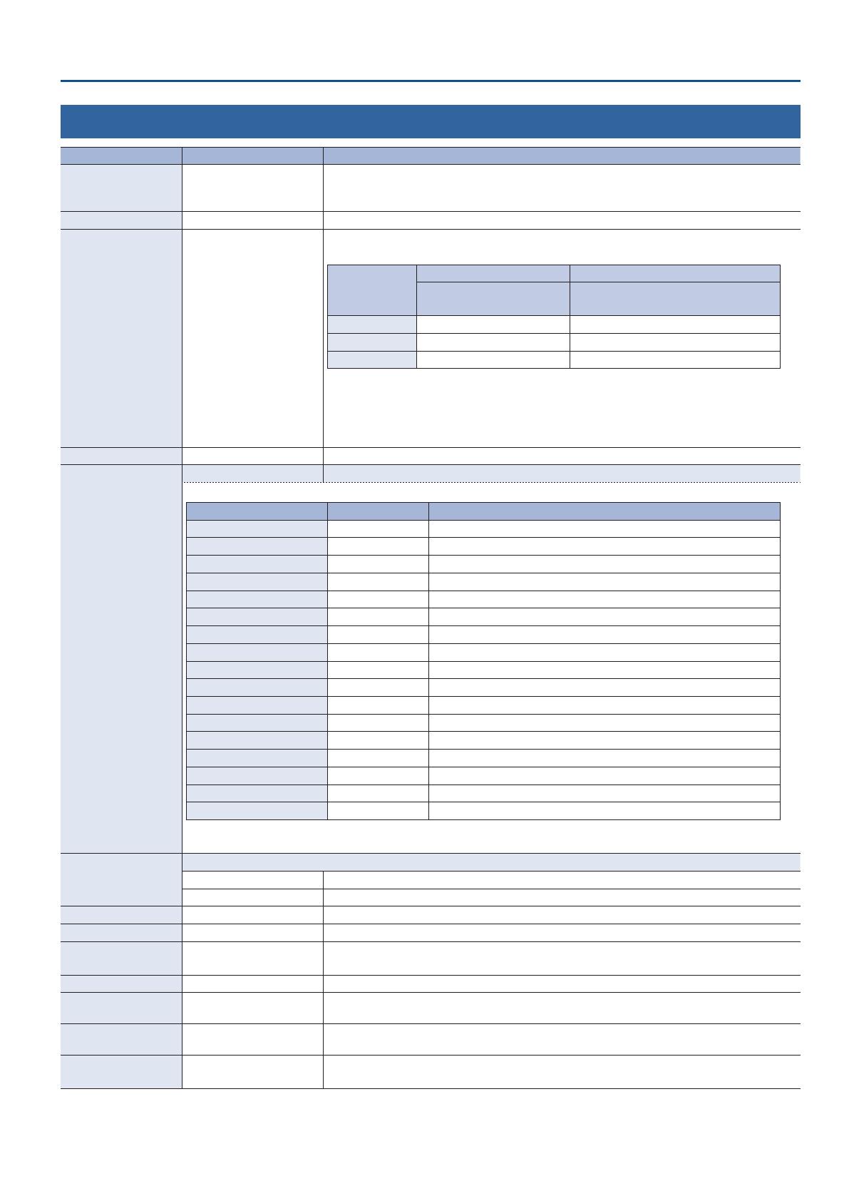
SYSTEM FORMAT 720p, 1080i, 1080p
This species the system format for the V-60HD. The input and output formats of the respective
connectors are determined according to the system format, as shown in the table below.
System format
Input format Output format
SDI IN 1–4 connectors
SDI OUT 1 and 2 connectors
HDMI OUT 1 and 2 connectors
1080p 1080p, 1080i 1080p
1080i 1080p, 1080i 1080i
720p 720p 720p
5 The input format of the HDMI IN 5 connector is set independently by the “EDID” value for “HDMI
IN 5” (p. 3), regardless of the system format.
5 The input format of the HDMI IN 6 connector or RGB/COMPONENT IN 6 connector is set
independently by the “EDID” value for “HDMI/RGB IN 6” (p. 4), regardless of the system format.
5 The output format at the MULTI-VIEW connector is xed at “1080p and cannot be changed.
PANEL OPERATION PGM/PST, A/B This sets the operation mode for video transitions.
PANEL LOCK
(ENTER) The PANEL LOCK menu items shown.
These specify whether panel lock is applied (ON) or not applied (OFF) for each individual button and knob.
Menu item Value Explanation
ALL SW & VOLUME OFF, ON All buttons and knobs
MENU SW + EXIT SW OFF, ON [MENU] [EXIT] buttons
VALUE ENCODER OFF, ON [VALUE] knob
PGM/A 1–8 SW OFF, ON PGM/A bus cross-point [1]–[8] buttons
PST/B 1–8 SW OFF, ON PST/B bus cross-point [1]–[8] buttons
AUX/MEMORY 1–8 SW OFF, ON AUX/MEMORY buttons (All)
MODE SW OFF, ON [MODE] button
CUT SW + AUTO SW OFF, ON [CUT] and [AUTO] buttons
VIDEO FADER OFF, ON Video fader
OUTPUT FADE SW OFF, ON [OUTPUT FADE] button
DSK ON/OFF SW OFF, ON [DSK] button
COMPOSITION BLOCK OFF, ON [H/PGM-CTR][V/PST-CTR] knobs, [PinP 1][PinP 2][SPLIT] buttons
TRANSITION BLOCK OFF, ON [MIX][WIPE 1][WIPE 2] buttons, [TIME] knob
DSK BLOCK OFF, ON [LEVEL][GAIN] knobs, [PVW] button
AUDIO IN 1–6 VOLUME OFF, ON AUDIO INPUT LEVEL knobs (All)
AUTO MIXING SW OFF, ON [AUTO MIXING] button
MASTER OUTPUT VOLUME OFF, ON [MASTER OUTPUT] knob
5 Press and hold the [EXIT] button and the [MENU] button at the same time (for 3 seconds or longer) to turn on panel lock.
Buttons and knobs for which panel lock is applied (ON) are locked.
OUTPUT FADE TYPE
This species the operation when the [OUTPUT FADE] button is pressed.
VIDEO Fade-ins and fade-outs are applied only to video.
VIDEO&AUDIO Fade-ins and fade-outs are applied simultaneously to video and audio.
LCD BACKLIGHT OFF, ON This illuminates (ON) or darkens (OFF) the backlight for the built-in display.
LCD CONTRAST 0–10–20 This adjusts the contrast for the built-in display.
LED DIMMER 0–7
This adjusts the brightness of the LEDs.
* When this is set to “0, the LEDs are not completely dark.
MULTI-VIEW LABEL OFF, ON When this is set to “ON, labels are displayed on the multi-view monitor.
MULTI-VIEW TALLY OFF, ON
When this is set to “ON, a tally border is displayed on the multi-view monitor. An AUX symbol is also
displayed for the video channel selected as the video on the AUX bus.
AUDIO LEVEL METER OFF, ON
When this is set to “ON, an audio level meter is displayed on the multi-view monitor. An A.F symbol
is also displayed for video channels for which Audio Follow is turned on.
AUTO SCAN OFF, ON
This sets the Auto Scan function on or o.
When this is set to “ON, channels 1 through 6 are switched automatically.
16
Menu List
Menu item Value (bold text: default value) Explanation
AUTO SCAN TIME
(ENTER) The AUTO SCAN TIME menu items shown.
Menu item Value Explanation
SDI IN 1–SDI IN 4
HDMI IN5, HDMI/RGB IN6
OFF, 0–5–120sec
Species the length of time that a video is shown when using auto scan.
If this is “OFF, video switching does not apply to that source.
STILL/BKG IN 7
STILL/BKG IN 8
OFF, 0–120sec
SCAN TRANSITION TIME 0.0–1.0–4.0sec
This species the length of the transition between video channels when using auto scan.
* You can also set this by holding down the [EXIT] button and turning the [TIME] knob.
AUTO SCAN SEQUENCE
This species the order in which video channels are shown when using auto scan.
NORMAL Switch sequentially in the order of channels 1–8.
RANDOM Switch randomly.
ON SCREEN MENU
OFF, UPPER LEFT,
UPPER RIGHT, LOWER LEFT,
LOWER RIGHT
This species the location of the OSD menu displayed on the multi-view monitor.
When this is set to “OFF, the OSD menu is always hidden.
AUTO OFF OFF, ON
This sets the Auto O function on or o. The power to the V-60HD turns o automatically when all
of the following states persist for 240 minutes.
5 No operation performed on the V-60HD
5 No audio or video input
5 No equipment is connected to the HDMI OUT connectors
DELETE STILL IMAGE
STILL IMAGE 1, STILL
IMAGE 2
This selects the memory whose still image is to be deleted. Pressing the [VALUE] knob lets you
delete the still image.
* A “
symbol is displayed for memory where a still image is saved.
MULTI-VIEW LAYOUT
This species the screen layout of the PVW section and PGM section shown in the multi-view monitor.
PVW.PGM PGM.PVW BLACK.PGM PGM.BLACK
PVW PGM PGM PVW PGM
The PVW section is not shown.
PGM
The PVW section is not shown.
MULTI-VIEW LABEL EDIT
IN1 SDI–IN4 SDI, IN5 HDMI,
IN6 HDMI, IN6 RGB, STILL1,
STILL2, PGM, PVW
Press the [VALUE] knob to access the MULTI-VIEW LABEL EDIT screen.
Here you can edit the label name for channels 1–6 shown in the multi-view monitor.
AUX LINKED PGM
OFF, ON When this is set to “ON, the same video as PGM is output to the AUX bus.
AUX LINKED PGM
This species whether the same video as the PGM bus is sent to the AUX bus (AUX link).
OFF Use the AUX/MEMORY buttons to select the video of the AUX bus.
AUTO LINK
MANUAL LINK
AUX link is enabled, and the same video as the PGM bus is sent to the AUX bus.
Temporarily disabling AUX link
When you press an AUX/MEMORY button, the selection of the AUX/MEMORY button is enabled (lit).
Re-enabling AUX link
AUTO LINK: When you operate the [AUTO] button etc. to switch the video of the PGM bus,
AUX link is automatically enabled.
MANUAL LINK: When you press the AUX/MEMORY button that is currently selected (lit red),
AUX link is enabled.
TEST PATTERN
OFF, 75% COLOR BAR,
100% COLOR BAR, RAMP,
STEP, HATCH
This species the test pattern.
TEST TONE
OFF
-20dB@1kHz : 1kHz
-10dB@1kHz : 1kHz
0dB@1kHz : 1kHz
-20dB@1kHz : 400Hz
-10dB@1kHz : 400Hz
0dB@1kHz : 400Hz
This species the test tone.
VIDEO FADER CALIBRATE
(ENTER)
The VIDEO FADER CALIBRATE screen appears.
Following the instructions on the screen, calibrate (adjust) the video fader.
FACTORY RESET
(EXEC) This returns the unit to its factory defaults.
VERSION
This displays the version of the system program.
17
Remotely Controlling a Camera
You can connect up to six cameras via the LAN port and remotely control them from the V-60HD.
This allows you to control cameras made by JVC, Panasonic, Canon, PTZOptics, and Avonic, and cameras that support VISCA over IP (such as Sony).
* Refer also to the owner’s manual of your camera.
Network Settings on the Camera
In order to control a camera from the V-60HD, you need to make
network settings on the camera. You can register up to six cameras.
1. Select the [MENU] button
0
CAMERA CONTROL.
2. Select the menu item, and use the [VALUE] knob to make
network settings.
Menu item Explanation
CAMERA ID Selects the camera to be controlled.
PROTOCOL
Species the cameras protocol.
JVC camera: JVC
Panasonic camera: Panasonic
Canon vcamera: Canon
Cameras that support VISCA over IP
(such as Sony): VISCA over IP
PTZOptics camera: PTZOptics
Avonic camera: Avonic
CAMERA IP ADDRESS Input the camera’s IP address.
LOGIN NAME
When “PROTOCOL is “JVC”
Press the [VALUE] knob to display the LOGIN
NAME screen. Enter the log-in name needed
to connect with the camera.
PASSWORD
When “PROTOCOL is “JVC”
Press the [VALUE] knob to display the
PASSWORD screen. Enter the password
needed to connect with the camera.
3. Press the [VALUE] knob to apply the setting.
4. Press the [MENU] button to quit the menu.
Controlling a Canon Camera
Heres how to control the settings of the connected camera from the
V-60HD.
1. Select the [MENU] button
0
CAMERA CONTROL
0
CAMERA ID.
2. Use the [VALUE] knob to select the camera that you want to
control, and press the [VALUE] knob to conrm.
3. Select a menu item, and use the [VALUE] knob to control the
cameras setting.
Menu item Explanation
SD CARD SLOT Species the SD card slot to use.
REC STATUS Indicates the video recording status.
REMAIN TIME
Indicates the remaining available recording
time.
WHITE BALANCE Species the white balance type.
TEMPERATURE (*1) Species the color temperature.
PRESET SET (*2)
When you press the [VALUE] knob, the
subject shown by the camera is captured as
the reference white color.
ZOOM Adjusts the camera’s zoom position. (*3)
ZOOM POSITION Adjusts the zoom position in six stages.
FOCUS Adjusts the focal point of the camera. (*3)
AUTO FOCUS
When this is set to “ON, the focal point is set
automatically.
FOCUS GUIDE If this is “ON, a focus guide is shown.
EXPOSURE Sets the exposure mode.
ND Species the type of ND lter.
IRIS Adjusts the aperture value.
SHUTTER Adjusts the shutter speed.
GAIN Adjusts the gain.
AE SHIFT
Adjusts the amount of exposure
compensation when using auto exposure.
(*1) This can be set if WHITE BALANCE” is “COLOR TEMPERATURE.
(*2) This can be set if WHITE BALANCE” is “PRESET 1” or “PRESET 2.
(*3) You can control the camera while holding down the [VALUE] knob.
4. Press the [VALUE] knob to apply the setting.
5. Press the [MENU] button to quit the menu.
18
Remotely Controlling a Camera
Controlling a JVC/Panasonic/PTZOptics/Avonic Camera or
a Camera That Supports VISCA over IP
Registering Camera Settings in a Preset
Up to eight sets of settings such as camera position and focus can be
registered as presets.
A registered preset can be recalled when needed.
* Presets are saved in the camera itself.
1. Select the [MENU] button
0
CAMERA CONTROL
0
CAMERA ID.
2. Use the [VALUE] knob to select the camera that you want to
control, and press the [VALUE] knob to conrm.
3. Select a menu item, and use the [VALUE] knob to control the
cameras setting.
Menu item Explanation
PAN Adjusts the horizontal position of the camera. (*1)
TILT Adjusts the vertical position of the camera. (*1)
PAN/TILT SPEED
Adjusts the speed at which the camera changes
direction.
ZOOM Adjusts the cameras zoom position. (*1)
FOCUS Adjusts the focal point of the camera. (*1)
AUTO FOCUS
When this is set to “ON, the focal point is set
automatically.
EXPOSURE Sets the exposure mode.
TALLY CH
Species the channel that is inputting the camera
video. When the camera video from the V-60HD is
the nal output, the cameras tally light is lit.
(*1) You can control the camera while holding down the [VALUE] knob.
4. Press the [VALUE] knob to apply the setting.
5. Select CAMERA PRESET STORE.
6. Use the [VALUE] knob to select the preset (1–8) in which you
want to register the settings, and press the [VALUE] knob.
A conrmation message appears.
If you want to cancel the operation, press the [EXIT] button.
7. Use the [VALUE] knob to select YES, then press the [VALUE]
knob.
The camera settings are registered in the preset.
8. Press the [MENU] button to quit the menu.
Recalling a Preset
Recalling from a Single Camera
1. Select the [MENU] button
0
CAMERA CONTROL
0
set
ALL CAMERAS RECALL to OFF.
2. Press and hold the [MODE] button to make it light up in
light blue.
Lit light blue
The unit is in camera preset mode. The AUX/MEMORY buttons
operate as preset select buttons.
3. Using the [VALUE] knob, change the “CAMERA ID” to select
the camera whose preset you want to recall.
4. Press the AUX/MEMORY button for the preset number
whose setting you want to recall.
The preset recalled from the camera.
5. To exit camera preset mode, press the [MODE] button to
make it light green or blue.
Recalling from All Cameras Simultaneously
1. Select the [MENU] button
0
CAMERA CONTROL
0
set
ALL CAMERAS RECALL to ON.
2. Press and hold the [MODE] button to make it light up in
light blue.
Lit light blue
The unit is in camera preset mode. The AUX/MEMORY buttons
operate as preset select buttons.
3. Press the AUX/MEMORY button for the preset number
whose setting you want to recall.
Presets are recalled from all cameras simultaneously.
4. To exit camera preset mode, press the [MODE] button to
make it light green or blue.
19
Control Using the TALLY/GPI Connector
You can operate the V-60HD remotely from an external device by inputting a GPI control signal via the TALLY/GPI connector.
And you can output a tally signal from the TALLY/GPI connector.
Specication of the TALLY/GPI Connector
Pin layout
5 4 3 2 1
1516171819202122232425 14
10111213 9 8 7 6
DB-25 type (female)
Tally output
Trigger method Open collector
Maximum input 12 V/200 mA
Control input
Trigger method
No-voltage contact
(make-contact) triggering
Contact capacity DC 24 V 0.1 A or higher
Input method Photocoupler
Pin assignments
Pin No. Function Pin No. Function
1 TALLY 1 PGM 14 N.C.
2 TALLY 1 PST 15 N.C.
3 TALLY 2 PGM 16 N.C.
4 TALLY 2 PST 17 GND
5 TALLY 3 PGM 18 GPI 1
6 TALLY 3 PST 19 GPI 2
7 TALLY 4 PGM 20 GPI 3
8 TALLY 4 PST 21 GPI 4
9 TALLY 5 PGM 22 GPI 5
10 TALLY 5 PST 23 GPI 6
11 TALLY 6 PGM 24 GPI 7
12 TALLY 6 PST 25 GPI 8
13 N.C.
* Never connect anything to an N.C. pin.
Outputting a Tally Signal
A tally signal is output from the connector pin corresponding to the
video channel being output, also including video composition and
transition eects.
Inputting a Control Signal
To operate the V-60HD remotely using control-signal input, you rst
assign the function to a GPI channel (1 through 8).
1. Select the [MENU] button
0
“RS-232/GPI”
0
GPI 1 TYPE”
through “GPI 8 TYPE.
2. Use the [VALUE] knob to specify the function to assign to
the GPI channel (1 through 8).
Value Explanation
N/A No function is assigned.
PGM CH SEL 1–8 Switches the nal output video.
PST CH SEL 1–8
Switches the preset video (the video to be
output next).
MEMORY LOAD 1–8 Loads a preset memory.
DSK SRC SEL 1–8
During DSK compositing, switches the
channel of the overlaid logo or image.
MUTE AUDIO IN 1–5/6
Turns the input audio mute function on/o.MUTE SDI IN 1–4
MUTE HDMI IN 5–6
SOLO AUDIO IN 1–5/6
Turns the input audio solo function on/o.SOLO SDI IN 1–4
SOLO HDMI IN 5, 6
DSK SW
Performs the same operation as pressing
the [DSK] button.
AUTO SW
Performs the same operation as pressing
the [AUTO] button.
CUT SW
Performs the same operation as pressing
the [CUT] button.
OUTPUT FADE SW
Performs the same operation as pressing
the [OUTPUT FADE] button.
AUTO MIXING SW
Performs the same operation as pressing
the [AUTO MIXING] button.
3. Press the [VALUE] knob to apply the setting.
4. Press the [MENU] button to quit the menu.
When a control signal is input from an external source, the
assigned function is executed. The GPI trigger is xed at the
trailing edge (low: ON).
20
LAN/RS-232 Command Reference
V-60HD support two types of remote-interface communication: LAN and RS-232.
Using the CONTROL port (LAN) or RS-232 connector to send specic commands to the V-60HD from a controlling device lets you operate the V-60HD
remotely.
LAN Interface
This uses the CONTROL port on the V-60HD.
You use Telnet to operate the V-60HD remotely over a LAN
(TCP/IP protocol).
Communication standards
Port CONTROL port (LAN)
Protocol TCP
Port number 8023
Setting the IP address of the V-60HD
1. Select the [MENU] button
0
“LAN CONTROL.
2. Select a menu item, then use the [VALUE] knob to set the IP
address.
Menu item Explanation
CONFIGURE
Sets whether the IP address and subnet mask
are obtained automatically (USING DHCP) or set
manually (MANUALLY).
IP ADDRESS
Sets the IP address when “CONFIGURE” is set to
“MANUALLY.
Set this in accordance with the connected network.
SUBNET MASK
Sets the subnet mask when “CONFIGURE” is set to
“MANUALLY.
Set this in accordance with the connected network.
3. Press the [VALUE] knob to apply the setting.
4. Press the [MENU] button to quit the menu.
Verifying the LAN information
1. Select the [MENU] button
0
“LAN CONTROL
0
“INFORMATION.
2. With the cursor positioned at “ENTER, press the [VALUE]
knob.
You can check and verify the following information.
Indication Explanation
STATUS Displays the connection status.
IP ADDRESS Displays the IP address.
SUBNET MASK Displays the subnet mask.
MAC ADDRESS Displays the MAC address.
3. Press the [MENU] button to quit the menu.
RS-232 Interface
RS-232 connector pin layout Pin assignments
1 2 3 4 5
6 7 8 9
DB-9 type (male)
Pin No. Signal
1 N.C.
2 RXD
3 TXD
4 DTR
5 GND
6 DSR
7 RTS
8 CTS
9 N.C.
Communication standards
Communication method Synchronous (asynchronous), full-duplex
Communication speed 9,600 /38,400 bps
Parity none
Data length 8 bits
Stop bit 1 bit
Code set ASCII
Flow control XON/XOFF
Cable wiring diagram
Use an RS-232 crossover cable to connect the V-60HD and the
controller (an RS-232-compatible computer or other device).
V-60HD Controller
N.C.: 1 1:
RXD: 2 2: RXD
TXD: 3 3: TXD
DTR: 4 4:
GND: 5 5: GND
DSR: 6 6:
RTS: 7 7:
CTS: 8 8:
N.C.: 9 9:
(Crossover connection)
* The connections between 4 and 6 and between 7 and 8 are inside
the V-60HD.
Command Format
Commands are formatted using the conguration shown below.
Commands are all in ASCII code.
stx Command code : Parameter , Parameter ;
stx
ASCII code “02H” is a control code indicating the start of a
command. “H” indicates that it is a hexadecimal value.
Command
code
This species the command type (3 letters of the alphabet).
Parameter
This is appended to a command that requires one or more
parameter. The command and the parameter portion
are separated by a “ : ” (colon). When there are multiple
parameters, they are each separated by “ , ” (comma)
characters.
;
This is the code that the V-60HD recognizes as the end of
a command.
* The codes of stx (02H), ACK (06H), and XON (11H)/ XOFF (13H) are
the control codes.
  • Page 1 1
  • Page 2 2
  • Page 3 3
  • Page 4 4
  • Page 5 5
  • Page 6 6
  • Page 7 7
  • Page 8 8
  • Page 9 9
  • Page 10 10
  • Page 11 11
  • Page 12 12
  • Page 13 13
  • Page 14 14
  • Page 15 15
  • Page 16 16
  • Page 17 17
  • Page 18 18
  • Page 19 19
  • Page 20 20
  • Page 21 21
  • Page 22 22
  • Page 23 23
  • Page 24 24

Roland V-60HD Reference guide

Type
Reference guide

Ask a question and I''ll find the answer in the document

Finding information in a document is now easier with AI