RGBlink M1 Quick start guide

Type
Quick start guide

RGBlink M1 is an all-in-one video processing solution that offers a range of capabilities for professional applications, including video mixing, scaling, and audio processing. With its modular design, M1 supports various input and output options, allowing users to connect multiple signal sources and seamlessly switch between them. It features two video layers for compositing, along with additional layers for OSD, logos, and stills. The device also includes a mask feature for the foreground layer, enabling users to create custom shapes and effects.

RGBlink M1 is an all-in-one video processing solution that offers a range of capabilities for professional applications, including video mixing, scaling, and audio processing. With its modular design, M1 supports various input and output options, allowing users to connect multiple signal sources and seamlessly switch between them. It features two video layers for compositing, along with additional layers for OSD, logos, and stills. The device also includes a mask feature for the foreground layer, enabling users to create custom shapes and effects.

M1
Quick Start
Modular design throughout
Support hot swap modules
Preview 4 inputs
Seamless switching between PST and PGM
Multiple audio outputs available
2 video layers plus additional layers for OSD,LOGO,STILL
Mask feature for forground layer including support
for user defined mask
Compatible with all display types
Genlock Y In
Save Presets and settings on board and to USB
14 Transition Effects on the T-bar and TAKE button
2
/25
CONTENTS
Product Introduction..............................................................................................................................................3
Packing Configuration
................................................................................................................................................. 4
Hardware Orientation
................................................................................................................................................. 5
Front Panel.......................................................................................................................................................... 5
Rear Panel........................................................................................................................................................... 9
Using Your Product
.................................................................................................................................................... 10
Menu Structure..................................................................................................................................................10
PST Mode..........................................................................................................................................................12
PGM Mode........................................................................................................................................................17
Switching Mode................................................................................................................................................ 18
Set the Output Parameter.................................................................................................................................. 19
Using Black Out................................................................................................................................................21
Lock Front Panel...............................................................................................................................................22
Language/语言..................................................................................................................................................22
System Setting...................................................................................................................................................22
Factory Reset.....................................................................................................................................................23
Contact Information.............................................................................................................................................24
3
/25
Product Introduction
M1 is All-in-one scaling and vision mixing Tools.
M1 can be up-down and cross-convert any input signal to the output, support 2 layers seamless
switching from preview to PGM. Supports Integrated audio also.
Operator can run M1 by its touch panel and its operations control panels, preview all the inputs
and Preset by its PVW HDMI output ports, and seamless switching on its PGM program output
port, with seamless transition efforts including Fade or Wipe.
M1 is not only a traditional video mixer, but also a video scaler by its integration pixel scale engine
for the modern displays, including LED display, which user doesn’t need to have a video scaler
behind.
And M1 is fully modular base to meet different flexible configuration requirement.
System Connection
RGBlink video processing solutions provide
a range of flexible configuration options for
professional applications.
M1 System Connection Diagram
4
/25
Packing Configuration
Note:
AC Power Cable supplied as standard according to destination market.
USB is contained on the Warranty/Registration Card. Please keep.
Network Cable
Cable DVI a HDMI
Screw Driver
5
/25
Hardware Orientation
Front Panel
Panel Instruction
1
Audio adjust area
5
Menu and LCD display area
2
Audio input area
6
Switching mode area
3
PGM output area and Logo button
7
Function area
4
PST output area and Logo button
8
Layer selection area
5
8
1
2
3
4
6
7
6
/25
Audio adjust area
1
SOURCE FADER
Source fader adjust 4 input signals' voice separatly to same value, each signal request to
save.
Remark: adjustment may not work if push it quickly
MASTER FADER
MASTER FADER is an amplification-factor of all channel invoice, come true Source
value multiply by current Master value
Remark: adjustment may not work if push it quickly
CUE
CUE is to switch PST audio preview or PGM audio preview.
MUTE
MUTE is for single audio output/Mix audio output
Audio input area
2
SAVE
To adjust M1 audio input and output.
LOAD
Press load button once to lock audio; press load button for 3 seconds to factory reset.
1/2/3/4/5
The button 1/2/3/4/5 is to select audio input.
PGM output area and Logo button
3
LED INDICATOR
The button 1/2/3/4/LOGO is lit when the signal or background input is selected for use.
PGM AREA
For indicating, user can not change the channel or set the size or position in PGM area.
LOGO
For fade out to black softly
1/2/3/4/5
Each button is numbered and can be used as direct number entry when values such as
resolution and size.
7
/25
PST output area and Logo button
4
LED INDICATOR
The button 1/2/3/4/LOGO is lit when the signal or background input is selected for use.
PST AREA
For indicating, user can not change the channel or set the size or position in this area.
LOGO
For switching from PGM to test pattern.
6/7/8/9/0
Each button is numbered and can be used as direct number entry when values such as
resolution and size.
PST AREA
For indicating, the button is lit when output the signal in PST channel.
For selecting, push any button to switch the PST signal.
For editing, (button light is lit -- the channel is used but can not be edited, button light is
flashing -- the channel can be edited, button light is off -- the channel is not selected.
Menu and LCD Display Area
5
MENU
Menu and exit reuse button.
SELECT/ENTER
Confirmation button.
LCD DISPLAY
Displays current status of the product, and for feature selections provides interactive
choices in conjunction with buttons on the Rear Panel.
Switching Mode Area
6
CUT
Zero delay switching.
TAKE
Seamless switching with transition effects.
T-BAR
WIPE and mix switching.
8
/25
Funtion Area
7
MASK
Choose the button to full screen the selected layer
SCALE
Press this button to set PIP in PST window.
Remar: Press the button to open PIP, select A/B layer to close PIP.
Layer Selection Area
8
A/B
For adding or deleting the layer, the button light is lit when add the layer, off when
delete the layer, and flash when select the layer.
9
/25
Rear Panel
Input Interface
1
Optional Input Module
4 input card slots, supports input signals including DVI, HDMI, USB, SDI.
Each DVI module supports 1 DVI-I input and compatible CVBS, VGA,YPbPr.
Each HDMI module supports 1 HDMI-A input
Each USB module supports 1 USB-B input and 1 USB backup.
Each SDI module supports 1 SDI input and 1 SDI loop out.
Output Interface
2
HDMI PVW Output
3
HDMI PGM Output
4
SDI PGM Output (Optional, not standard)
Audio Area
5
Audio In
Audio Out
Audio Out (Earphone)
Control Interface
6
Genlock input BNC port
7
LAN port RJ-45
8
USB port USB-A
9
TALLY Light
Power Connection
10
Power Switch
11
AC 85-264V Max 65W, IEC-3
10
/25
Using Your Product
Menu Structure
The menu structure is shown on the LCD Screen and in the figure below:
LCD Touch Screen Menu Instruction
1
Return Button
12
DSK
2
Homepage
13
BLEND
3
Information Page
14
FREEZE
4
Input Resolution Display
15
BLACK
5
Output Resolution Display
16
Audio In
6
Input Menu
17
Audio Out
7
Output Menu
18
Lock Rear Panel
8
LOGO
19
Language/语言
9
MASK
20
System
10
Scale
21
Factory Reset
11
Transition Effect
11
/25
Customized version for broadcasting
12
/25
PST Mode
M1 supports 1 HDMI preview output, and it supports the functions as below:
Signal Selection
Push any button in PGM or PST output area, for example, push the button [5], the border of signal 5 will change
to yellow, and the signal in PGM monitor will be changed to signal 5.
Add or Delete Layer
Push any button of [A] to [B] in Layer Selection Area to add or delete the layer.
Add layer: The light is lit.
Select layer: The light is flashing.
Delete layer: The light is off.
Freeze the Layer
Push the [FREEZE] button in LCD screen, Select as needed to freeze layer A, layer B or 2 layers, push the
button<Live> , the layer is live.
2 Layers Presets
1. Push A or B button in Layer selection Area to select 1 or 2 layouts, including 1P, PIP.
2. User can adjust the position, size for the selected layer, and set DSK, BLEND and MASK, some function
coming soon.
Set the Position
1. Push any button of [A] to [B] in Layer Selection Area, the light is red lit when the layer is selected.
2. Push the [SCALE] button in Layer Adjustment Area or on the LCD screen, and enter to the menus as
follows:
Use the rotary knob to adjust the position of the layer.
->H Pos 465
V Pos 1248
H Size 956
V Size 540
Reset >>
FREEZE A FREEZEB FREEZE ALL LIVE
13
/25
Scale and Crop the Layer
1. Push any button of [A] to [B] in Layer Selection Area, the light is flashing when the layer is selected.
2. Touch on LCD screen, and enter to the menus as follows:
Use the rotary knob to adjust the size of the layer.
If select <Crop>, it will enter to the menus as follows:
Crop H Pos: Crop the horizontal position.
Crop V Pos: Crop the vertical position.
Crop H Size: Crop the horizontal size.
Crop V Size: Crop the vertical size.
Reset: Reset crop if image quality distorts by improper operation.
DSK Setting
1. Firstly, enable the 2 layers function.
2. Push [MENU] button, and enter to the menu items. Turn the rotary knob, and select <DSK> option in LCD
screen, rotary the knob or touch the <DSK> to confirm.
Preset: Can select user, black background, white background, red background, green background and blue
background.
Mode: Select Key In or Key Out.
Alpha: The adjustment range is between 0~128.
Red Min: The adjustment range is between 0~255.
Red max: The adjustment range is between 0~255.
Green Min: The adjustment range is between 0~255.
Green Max: The adjustment range is between 0~255.
Blue Min: The adjustment range is between 0~255.
Blue Max: The adjustment range is between 0~255.
DSK: Can select enable or disable the DSK function.
-> Crop H Pos 0
Crop V Pos 0
Crop H Size 1920
Crop V Size 1080
Reset >>
Preset Black BlackGround
Mode Key In
Alpha 128
Red Min 0
Red Max 208
Green Min 0
Green Max 208
Blue Min 0
Blue Max 208
DSK ON
14
/25
Transitions Setting
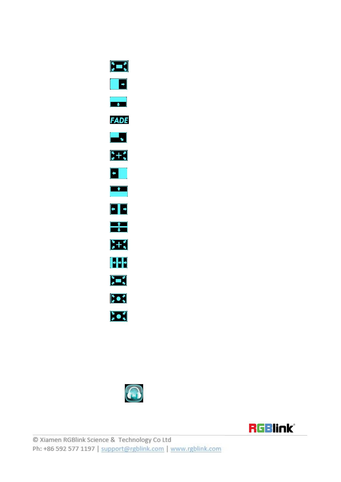
1. Touch the transition buttons in LCD screen, M1 supports 15kinds of wipe modes:
Touch the transition button , user can select ←[]→.
Touch the transition button , can select L→R.
Touch the transition button , user can select T→B.
Touch the transition button , can select fade.
Touch the transition button , user can select LT→RB.
Touch the transition button , user can select →.
Touch the transition button , user can select L←R.
Touch the transition button , user can select B→T.
Touch the transition button , user can select L←M→R.
Touch the transition button , user can select T←M→B.
Touch the transition button , user can select →+←.
Touch the transition button , user can select III→.
Touch the transition button , user can select →[]←.
Touch the transition button , user can select ←O→.
Touch the transition button , user can select →O←.
2. Push the [TAKE] button, or use T-bar switcher to switch the image to program with selected wipe.
Audio In Setting
1. Push [MENU] button, and enter to the menu items. Turn the rotary knob, select <Audio In> option in LCD
screen, rotary the knob or touch the directly to confirm.
15
/25
2. Select the Audio input 1-4 for setting :
Audio Source Sel: Embedded or External
Audio Gain: The adjustment range is between 0~100
Audio Delay: The adjustment range is between 0~20ms
Audio Out Setting
1. Push [MENU] button, and enter to the menu items. Turn the rotary knob, select <Audio Out> option in LCD
screen, rotary the knob or touch the directly to confirm.
2. Select the Audio Output for setting :
Audio Source Sel: Select Layer A or Layer B
Audio Gain: The adjustment range is between 0~100
Monitor Select: Select PST or PGM
Mute: Select On or Off
BLEND Setting
1. Push [MENU] button, and enter to the menu items. Turn the rotary knob, select <BLEND>option in LCD
screen, rotary the knob or touch the directly to confirm.
Layer Select: Select Layer A or Layer B
Blending Mode: Including 3D Frame, Pure Color Frame, Outside, Inline 4 modes
Blending Width: The adjustment range is between 1~90
On/Off: Select On or Off
Audio Source Sel Embedded
Audio Gain 0
Audio Delay 0 ms
Audio Source Sel Layer A
Audio Gain 0
Monitor Select 0
Mute On
Layer Select Layer A
Blending Mode 3D Frame
Blending Width 0
On/off On
16
/25
Mask Setting
1. Push [MENU] button, and enter to the menu items. Turn the rotary knob, select <Mask>option on LCD screen,
rotary the knob or touch the directly to confirm.
2. Select the Mask for setting :
Customs: Coming soon
Custom LOGO
1. Push [MENU] button, and enter to the menu items. Turn the rotary knob, select <LOGO>option in LCD screen,
rotary the knob or touch the directly to confirm.
Mask
Mask Mask Layer Mask & PIC POS
Mask
Heart 0
Oval 0
Round 0
Crescent Left 0
Star 0
Diamond 0
Custom 1 0
Logo
Capture Logo Logo Present Delete Logo
17
/25
PGM Mode
1. Switch the edited PST image to program by pushing the [CUT], [TAKE] button or T-bar, and then the PGM
image will return to PST state, which can be edited.
2. There are 1 HDMI output and 1SDI output for program, and maximum realize 1920x1080 output.
18
/25
Switching Mode
1. T-BAR switch: Switch the PST image to program with wipe and fade by T-bar.
2. CUT switch: Seamless switch the PST image to program by pushing [CUT] button.
3. TAKE switch: Switch the PST image to program with wipe and fade by pushing [TAKE] button.
4. CUE: Switch PST audio preview or PGM audio preview by pushing [CUE] button.
5. MUTE: Switch single audio output/Mix audio output.
19
/25
Standard C_1024×768@60
Custom Format On
HActive 1024
VActive 768
Freq 60
Set >>
Set the Output Parameter
1. Select the Output Resolution
Push the [MENU] button, and enter to the menu items, turn the rotary knob and select <Output> or :
Push the rotary knob to confirm, and enter to the menus as below:
<Output Format> is the default option, push the rotary to confirm. Turn the rotary knob, select the output
resolution according to actual need.
Customs Output Resolution
Continue the above operation, setting the HActive, VActive, Freq, and select <Set>, confirm the Set setting to
Yes.Then the LCD screen shown as below:
2. Output Setting
Push the rotary knob or touch the button <Output setting> to confirm, and enter to the menus as below:
PST and PGM can be choose DVI or HDMI as output port, SDI Level choose Level A or Level B.
Output Format
Output Setting
External Sync
Test Pattern
PST DVI
PGM DVI
SDI Level Level A
20
/25
3. External Sync
External Including option Off and On,
Input will shown as actual input resolution.
Format support choose 2 default resolution: 1280x720 @60 & 1920x1080 @60.
4. Test Pattern
Output: Select PST or PGM
Test Pattern: Select Off, Color Bar, Solid Color
Red: The adjustment range is between 0~255
Green: The adjustment range is between 0~255
Blue: The adjustment range is between 0~255
External Sync
External Off
Input No Input
Format 1920x1080 @60
Test Pattern
Output PST
Test Pattern Off
Red 0
Green 0
Blue 0
  • Page 1 1
  • Page 2 2
  • Page 3 3
  • Page 4 4
  • Page 5 5
  • Page 6 6
  • Page 7 7
  • Page 8 8
  • Page 9 9
  • Page 10 10
  • Page 11 11
  • Page 12 12
  • Page 13 13
  • Page 14 14
  • Page 15 15
  • Page 16 16
  • Page 17 17
  • Page 18 18
  • Page 19 19
  • Page 20 20
  • Page 21 21
  • Page 22 22
  • Page 23 23
  • Page 24 24

RGBlink M1 Quick start guide

Type
Quick start guide

RGBlink M1 is an all-in-one video processing solution that offers a range of capabilities for professional applications, including video mixing, scaling, and audio processing. With its modular design, M1 supports various input and output options, allowing users to connect multiple signal sources and seamlessly switch between them. It features two video layers for compositing, along with additional layers for OSD, logos, and stills. The device also includes a mask feature for the foreground layer, enabling users to create custom shapes and effects.

Ask a question and I''ll find the answer in the document

Finding information in a document is now easier with AI