Page is loading ...

TECHNICAL MANUAL
INSTALLATION MANUAL FOR EXPORT UNITS
SERVICE MANUAL FOR DOMESTIC UNITS
FOR JACKSON MODELS:
10A
10AB
10APRB
10U
HIGHER HOOD OPTION
JACKSON MSC, INC.
P.O. BOX 1060
HIGHWAY 25E
BARBOURVILLE, KY. 40906
FAX: (606) 523-9196
PHONE: (606) 523-9795
www.jacksonmsc.com
An
Company
10 SERIES, ELECTRICALLY HEATED, ROUND DISHMACHINES
February 26, 2004
P/N 7610-002-41-09 (Revision D)


i
REVISION
REVISION
DATE
MADE
BY
APPLICABLE
ECN
DETAILS
D 02-26-04 MAW 6742
Added 10U installation pictures and the 10U description to the
applicable parts. Converted manual to new design.

ii
NOMENCLATURE FOR THE MODELS COVERED IN THIS MANUAL:
10 SERIES
10A = 10 without a booster tank
10AB = 10 with a booster tank
10APRB = 10 with a booster tank and a power rinse pump
10U = 10 with a booster tank, a 4” shorter hood, and 9” shorter legs
Higher Hood Option = A hood that is 5” higher than the standard hood
Model:
Serial No.:
Installation Date:
Service Rep. Name:
Phone No.:
Jackson MSC Inc. provides technical support for all
of the dishmachines detailed in this manual. We
strongly recommend that you refer to this manual
before making a call to our technical support staff.
Please have this manual with you when you call so
that our staff can refer you, if necessary, to the prop-
er page. Technical support is available from 8:00
a.m. to 5:00 p.m. (EST), Monday through Friday.
Technical support is not available on holidays.
Contact technical support toll free at 1-888-800-
5672. Please remember that technical support is
available for service personnel only.

iii
TABLE OF CONTENTS
SECTION DESCRIPTION PAGE
I. SPECIFICATION INFORMATION
Operating & Electrical Requirements 2
10A Dimensions 3
10AB/10APRB/10U Dimensions 4
Table Dimensions 5
II. INSTALLATION/OPERATION INSTRUCTIONS
Visual Inspection/Unpacking the Dishmachine 7
Leveling the Dishmachine/Installing the Vacuum Breaker & Plumbing 8
Installing the Internal Vacuum Breaker/Hood Assembly 9
Plumbing the Dishmachine/Drain Line Connection/Electrical Connection 10
Final Check 11
Operation Instructions 12
Detergent Control 13
III. PREVENTATIVE MAINTENANCE
Preventative Maintenance 15
IV. SERVICE PROCEDURES
Rinse Head/Wash Head Assemblies 17
Timer for 10 Dishmachines 18
Function of Switches, Circuit Breaker & Indicating Lights 19
Replacement of Switches in Control Panel 19
Thermostat Adjustment 20
Rinse Tank Heater System 21
Wash Tank Heater System 22
Water Level Control 23
Water Level Control (APRB) 24
Replacing Seal and Ceramic on Wash and Rinse Pumps 25
V. TROUBLESHOOTING 26
VI. PARTS SECTION
10A Assembly 31
10AB/APRB Assembly 32
Control Box Assembly 33
Ordering Replacement Wire/Conduit & FIttings 35
Ordering Replacement Conduit, FIttings, & Hose 36
Tub Assembly 37
Bottom View Assembly 39
Wash Tank Cross View/Tub to Booster Connection 41
10AB/APRB Rinse Booster & Associated Parts 42
Pump & Motor Assembly 43
Thermostat Housing Assembly 44
Incoming Plumbing Assemblies 45
Solenoid Valve Repair Kit / Vacuum Breaker Repair Kit 46
Hood & Associated Assemblies 47
Vacuum Breaker/Connector Assemblies 10A Series 49
Vacuum Breaker/Connector Assemblies 10AB/10APRB/10U 50
Parts List for 10 Dishmachines 51

iv
TABLE OF CONTENTS
IV. ELECTRICAL SCHEMATICS
10A 208 - 220 V, 60 HZ, single phase 54
10AB/10U 208 - 220 V, 60 HZ, single phase 54
10AB/10U 208 - 220 V, 60 HZ, three phase 54
10APRB 208 - 220 V, 60 HZ, single phase 54
10APRB 208 - 220 V, 60 HZ, three phase 54
WIRING DIAGRAMS
10A 208 - 220 V, 60 HZ, single phase 55
10AB/10U 208 - 220 V, 60 HZ, single phase 56
10AB/10U 208 - 220 V, 60 HZ, three phase 57
10AB/APRB 208 - 220 V, 60 HZ, single phase 58
10AB/APRB 208 - 220 V, 60 HZ, three phase 59
V. JACKSON MAINTENANCE & REPAIR CENTERS 60

1
SECTION 1:
SPECIFICATION INFORMATION

2
SECTION 1: SPECIFICATION INFORMATION
10 SERIES SPECIFICATIONS
PERFORMANCE/CAPABILITIES
OPERATING CAPACITY (RACKS/HOUR)
RACKS PER HOUR 45
DISHES PER HOUR 950
GLASSES PER HOUR 950
OPERATING CYCLE (SECONDS)
WASH TIME 60
RINSE TIME 10
TOTAL CYCLE TIME 72
TANK CAPACITY (GALLONS)
WASH TANK 4.5
BOOSTER TANK (10AB/10APRB/10U ONLY) 3.0
PUMP CAPACITY (GALLONS)
WASH PUMP 70 GPM
TEMPERATURES
WASH---°F (MINIMUM) 150
RINSE---°F (MINIMUM) 180
ELECTRICAL REQUIREMENTS
WASH PUMP MOTOR HP 1/2
RINSE PUMP MOTOR HP (10APRB ONLY) 1/2
MODEL VOLTS HERTZ PHASE AMPS
10A 208 60 1 8.23
10A 220 60 1 8.23
10AB/10U 208 60 1 38.8
10AB/10U 208 60 3 25.6
10AB/10U 220 60 1 37.2
10AB/10U 220 60 3 24.6
10APRB 208 60 1 43.4
10APRB 208 60 3 30.2
10APRB 220 60 1 41.8
10APRB 220 60 3 29.2
WATER REQUIREMENTS
INLET TEMPERATURE (10A) 180°F
INLET TEMPERATURE (10AB/10ABPRB/10U) 140°F
WATER LINE SIZE NPT (MINIMUM) 1/2”
DRAIN LINE SIZE I.D (MINIMUM) 1 1/2”
GALLONS PER HOUR 58
FLOW PRESSURE P.S.I. 20A5
FLOW RATE GPM 7.8
RACKS
DISH (17 1/2” DIAMETER ROUND) 1
GLASS AND SILVERWARE
(17 1/2” DIAMETER ROUND) 1
FOUR COMPARTMENT SILVERWARE 1

3
SECTION 1: SPECIFICATION INFORMATION
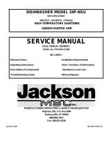
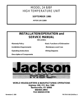
10A DIMENSIONS
NOTES:
A - Water inlet 1/2” NPT. Plumbing can be directed either left or
right.
B - Drain connection 1 1/2” NPT
C - Electrical connection
D - Clearance for dishes:
10” (10A 4” shorter hood)
14” (10A standard hood)
19” (10A 5” higher hood)
E - Machine height:
45 1/2” (9” shorter leg, 4” shorter hood)
58 1/4” (standard leg & hood)
63 1/4” (standard leg, 5” higher hood)
All dimensions in inches.
All vertical dimensions are +/- 1/2” from the floor
due to the adjustable bullet feet.
C
E
B
A
B
B
C
9”
13”
5 1/4”
1 13/16”
16 1/2”
27 1/2”
16 1/2”
14 7/8”
TO THE
WALL
21”
11”
14 1/2”
18”
19 1/4”
15 1/4”
4” SH
24 1/4”
5” HH
2 3/4”
CIRCUIT
BREAKER
4”
14” TO
INLET
5” 4” SH
ONLY
34”
22 1/4”
20 1/4”
4” SH
25”
4” SH
11 1/2”
4” SH
29 1/4”
5” HH
13 1/2”
28 3/4”
TOP VIEW
LEFT VIEW FRONT VIEW
VACUUM
BREAKER
D
19”

4
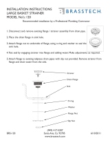
SECTION 1: SPECIFICATION INFORMATION
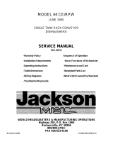
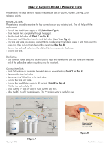
10AB/10APRB/10U DIMENSIONS
NOTES:
A - Water inlet 1/2” NPT. Plumbing can be directed either left or
right.
B - Drain connection 1 1/2” NPT
C - Electrical connection
D - Clearance for dishes:
10” (10U/10AB/10APRB 4” shorter hood)
14” (10A/10AB/10APRB standard hood)
19” (10A/10AB/10APRB 5” higher hood)
E - Power rinse pump motor (10APRB only)
F - Booster tank (10AB/10APRB/10U only)
G - Machine height:
45 1/2” (10U/10AB/10APRB, 9” shorter leg, 4” shorter hood)
58 1/4” (10AB/10APRB standard leg & hood)
63 1/4” (10AB/10APRB, standard leg, 5” higher hood)
All dimensions in inches.
All vertical dimensions are +/- 1/2” from the floor
due to the adjustable bullet feet.
A
B
E
F
A
B
B
C
A
E
F
D
G
9”
13”
5 1/4”
1 13/16”
16 1/2”
27 1/2” (AB ONLY)
16 1/2”
14 7/8”
TO THE
WALL
21”
19”
35 1/2” (APRB ONLY)
11”14 1/2”
18”
2 3/4”
4”
20 1/2”
34”
25”
10U ONLY
11 1/2”
10U ONLY
15 1/4”
10U
24 1/4”
5” HH
19 1/4”
5”
10U ONLY
14” TO
INLET
22 1/4”
20 1/4”
10U
29 1/4”
5” HH
5 1/2”
20”
TOP VIEW
LEFT VIEW
FRONT VIEW
CIRCUIT
BREAKER

5
SECTION 1: SPECIFICATION INFORMATION
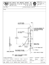
10 SERIES TABLE DIMENSIONS
10 1X PACKAGE
10 2X PACKAGE
10 3X PACKAGE
Legend
A - 10” High backsplash, 2” turnback at 45B
B - 3” High, 1 1/2” diameter rolled edge
C - Scrap block
D - Scrap basket with slide bars
E - 20” x 20” x 5” deep pre-rinse sink
F - Heavy duty pre-rinse
G - 20” Slanted wall mounted overshelf 42” long
H - 3 1/2” hole for sink drain with basket drain
I - 1 7/8” hole for hood support piping

6
SECTION 2:
INSTALLATION/OPERATION
INSTRUCTIONS

7
SECTION 2: INSTALLATION/OPERATION INSTRUCTIONS
INSTALLATION INSTRUCTIONS
Jackson MSC Inc. provides technical support for all of the dishmachines detailed in this manual. We strongly recommend that
you refer to this manual before making a call to our technical support staff. Please have this manual with you when you call so
that our staff can refer you, if necessary, to the proper page. Technical support is available from 8:00 a.m. to 5:00 p.m. (EST),
Monday through Friday. Technical support is not available on holidays. Contact technical support toll free at 1-888-800-5672.
Please remember that technical support is available for service personnel only.
VISUAL INSPECTION: Before installing the unit, check the
container (Fig. 1) and machine (Fig. 2) for damage. A damaged
container is an indicator that there may be some damage to
the machine. If there is damage to both the container and
machine, do not throw away the container. The dishmachine
has been inspected and packed at the factory and is expected
to arrive to you in new, undamaged condition. However, rough
handling by carriers or others may result in there being dam-
age to the unit while in transit. If such a situation occurs, do not
return the unit to Jackson; instead, contact the carrier and ask
them to send a representative to the site to inspect the dam-
age to the unit and to complete an inspection report. You must
contact the carrier within 48 hours of receiving the machine.
Also, contact the dealer through which you purchased the unit.
(Fig. 1) (Fig. 2)
UNPACKING THE DISHMACHINE: Note: Be
careful when cutting the hold down strap (Fig. 3), it
is under tension. Remove the hood (Fig. 4) and set
to the side. Please note (Fig. 5) for the location of
the O-rings. Once the machine has been removed
from the container, ensure that there are no miss-
ing parts (Fig. 5 & 6) from the machine. This may
not be obvious at first. If it is discovered that an
item is missing, contact Jackson immediately to
have the missing item shipped to you.
(Fig. 3) (Fig. 4)
(Fig. 5) (Fig. 6)

8
SECTION 2: INSTALLATION/OPERATION INSTRUCTIONS
INSTALLATION INSTRUCTIONS
LEVEL THE DISHMACHINE: The dishmachine is designed to operate while being level.
This is important to prevent any damage to the machine during operation and to ensure the
best results when washing ware. The unit comes with adjustable bullet feet, which can be
turned using a pair of channel locks or by hand if the unit can be raised safely. Ensure that
the top of the tub is level from side to side and from front to back before making any con-
nections.
INSTALLING THE DISHMACHINE: With the machine base set in place,
lift the table (Fig. 7) (with proper flange cutout) over and above machine
so that vertical flange on table cutout fits down inside of machine tub and
horizontal flange on machine tub fits up tight against underside of the
table.
(Fig. 7)
INSTALLING THE VACUUM BREAKER & PLUMBING: Ease
vacuum breaker piping (Fig. 8) supplied with the dishmachine
down through the square cutout in the backsplash of the table
(directly behind the machine). Connect vacuum breaker piping to
machine. The top union connects to its matching half on the bot-
tom of the rinse booster tank (Fig.9). The bottom union of the pip-
ing connects to an adapter pipe which, in turn connects to the
solenoid valve (Fig. 10). The arrows on the solenoid valve indicate
the direction of water flow to the machine. Tighten both of the con-
nections.
(Fig. 8)
(Fig. 9) (Fig. 10)

9
SECTION 2: INSTALLATION/OPERATION INSTRUCTIONS
INSTALLATION INSTRUCTIONS
ALIGNING THE MACHINE: Adjust the machine base to line up hole in table with hole in support
block (Fig. 11).
(Fig. 11)
INSTALLING THE INTERNAL VACUUM BREAKER: Insert internal vacuum
breaker pipe into hood support block pin end down (Fig.12).
WARNING: Internal vacuum breaker pipe must be installed or
there will be a hazard to the operator.
(Fig. 12)
INSTALLING THE HOOD ASSEMBLY: Make sure there are two “O-
rings” (Fig. 5) on the lower support pipe near the end of the ring. While
also holding the internal vacuum breaker, lift the hood and hood support
pipe up over table. Set hood support pipe down into the support block
hole (Fig. 13) and begin to work the hex nut into the hole. The locating
pin in the support block will insure proper line up. While holding the sup-
port pipe, start tightening nut by hand to prevent cross threading. It
should tighten considerable by hand. Then continue tightening with a
wrench. It may be necessary to work support pipe back and forth to seat
nut properly. When the nut is tight, it should force flat the stainless steel
and rubber washers tight to the table top.
(Fig. 13)
Attach vacuum breaker support pipe clamp (Fig. 14) to the support pipe and
external vacuum breaker piping. Slide up about 12” from the table and tight-
en securely. Position cover plate (supplied with table) over square cutout in
backsplash on table so that it fits tightly around piping then snap in the four
nylon fasteners (supplied) to hold in place.
Rotate the hood to insure it is free, if not, check level of machine, tightness
of table to machine flange, centering of machine, level of table and hood
support pipe.
(Fig. 14)

10
SECTION 2: INSTALLATION/OPERATION INSTRUCTIONS
INSTALLATION INSTRUCTIONS
PLUMBING THE DISHMACHINE: All plumbing connections must comply with all applicable local, state, and national plumb-
ing codes. The plumber is responsible for ensuring that the incoming water line is thoroughly flushed prior to connecting it to
any component of the dishmachine. It is necessary to remove all foreign debris from the water line that may potentially get
trapped in the valves or cause an obstruction. Any valves that are fouled as a result of foreign matter left in the water line, and
any expenses resulting from this fouling, are not the responsibility of the manufacturer.
CONNECTING THE DRAIN LINE: The drain for the dishmachine is a gravity discharge drain. Remove the overflow strainer
stopper from the tub and the unit will drain itself. There must also be an air gap between the machine drain line and the floor
sink or drain. If a grease trap is required by code, it should have a flow capacity of 5 gallons per minute.
WATER SUPPLY CONNECTION: Ensure that you have read the section entitled “PLUMBING THE DISHMACHINE” above
before proceeding. Install the water supply line (3/4” pipe size minimum) to the end of the Y-strainer. It is recommended that a
water shut-off valve be installed in the water line between the main supply and the machine to allow access for service. The
water supply line is to be capable of 25 PSI “flow” pressure at the recommended temperature indicated on the data plate. In
areas where the water pressure fluctuates or is greater than the recommended pressure, it is suggested that a water pressure
regulator be installed. The Model 10 does not come with water a pressure regulator as standard equipment.
Do not confuse static pressure with flow pressure. Static pressure is the line pressure in a “no flow” condition (all valves and
services are closed). Flow pressure is the pressure in the fill line when the fill valve is opened during the cycle.
It is also recommended that a shock absorber (not supplied with the dishmachine) be installed in the incoming water line. This
prevents line hammer (hydraulic shock), induced by the solenoid valve as it operates, from causing damage to the equipment.
PLUMBING CHECK: Slowly turn on the water supply to the machine after the incoming fill line and the drain line have been
installed. Check for any leaks and repair as required. All leaks must be repaired prior to placing the machine in operation.
ELECTRICAL POWER CONNECTION: Electrical and grounding connections must comply with the applicable portions of the
National Electrical Code ANSI/NFPA 70 (latest edition) and/or other electrical codes.
Disconnect electrical power supply and place a tag at the disconnect switch to indicate that you are working on the circuit.
Refer to the data plate for machine operating requirements, machine voltage, total amperage load and serial number.
To install the incoming power lines, first remove the lower control box cover (Fig. 15). Next, run the power lines through the
hole located in the bottom of the control box to the terminal board inside (Fig. 16). This board is accessible by removing the
lower cover plate on the control box. Attach lines (L1 and L2 (L3 for three phase)) on the terminal block at the lower front right
corner. There is no neutral wire on this machine. There is a grounding lug inside the control box on the bottom left. Be sure all
connections made are tightened properly. It is recommended that “DE-OX” or another similar anti-oxidation agent be used on
all power connections.
VOLTAGE CHECK: Ensure that the power switch is in the OFF position
and apply power to the dishmachine. Check the incoming power at the
terminal block and ensure it corresponds to the voltage listed on the data
plate. If not, contact a qualified service agency to examine the problem.
Do not run the dishmachine if the voltage is too high or too low. Shut off
the service breaker and mark it as being for the dishmachine. Advise all
proper personnel of any problems and of the location of the service break-
er. Replace the lower cover and tighten down the screws.
(Fig. 15) (Fig. 16)

11
SECTION 2: INSTALLATION/OPERATION INSTRUCTIONS
INSTALLATION INSTRUCTIONS
FINAL CHECK: Check all fittings and connections before and after first 10 cycles. Deliver Installation/Operation Manual to site
manager. Contact Jackson for free performance and installation check.

SECTION 2: INSTALLATION/OPERATION INSTRUCTIONS
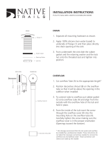
OPERATION INSTRUCTIONS
PREPARATION:
1. Ensure that the pump intake strainer (1) and basket overflow strainer (2) are
inserted and tight.
2. Ensure that the wash and rinse arms are installed and secure.
3. Remove all solid wastes in order to avoid obstructing filters, drain and wash and
rinse arms.
4. Ware that is encrusted with soil should be presoaked prior to being placed in the
machine.
5. When placing dishes into the racks, do not allow them to lean on each other.
6. Place the glasses upside down in the open rack. With the model 10 series, a four
compartment silverware rack is supplied. Place silver in compartment rack loosely
not allowing it to mix with other silverware of the same nature. Place the compart-
ment rack in the open rack and wash with the cups and glasses.
DAILY MACHINE PREPARATION: Refer to the section entitled “PREPARATION” at the top of this page and follow the instruc-
tions there. Afterwards, check that all of the chemical levels are correct and/or that there is plenty of detergent available for the
expected workload.
WARM-UP CYCLE: At the beginning of each work day, a warm up cycle will need to be performed. Close the hood (3). Turn
on the master switch (4). Raise the fill switch (5) until the machine is filled to the top of the basket overflow strainer (2.) Once
the proper water level has been reached, turn on the heater switch (6). Observe the temperature gauges, the rinse tempera-
ture should rise to a specified level of 180°F within five minutes if the incoming water to the booster tank is 140°F. The wash
heater will take longer to reach 150°F as the element is designed for maintaining temperature, not heating. Once the proper
temperature has been reached, with the hood closed, turn on the manual wash switch. You should hear the water being
pumped as it strikes the top of the hood. Turn off the manual wash switch. The dishmachine is now ready to proceed with wash-
ing of the dishes.
WARE PREPARATION: Proper preparation of ware will help ensure good results and less re-washes. If not done properly, ware
may not come out clean and the efficiency of the dishmachine will be reduced. It is important to remember that a dishmachine
is not a garbage disposal and that throwing unscraped dishes into the machine will defeat the purpose altogether of washing
the ware. Scraps should be removed from ware prior to being loaded into a rack. Pre-rinsing and pre-soaking are good ideas,
especially for silverware and casserole dishes. Place cups and glasses upside down in racks so that they do not hold water
during the cycle. The dishmachine is meant not only to clean, but to sanitize as well, to destroy all of the bacteria that could be
harmful to human beings. In order to do this, ware must be properly prepared prior to being placed in the machine.
WASHING A RACK OF WARE: To wash a rack, open the hood completely (being careful for hot water that may drip from the
top of the hood), manually load detergent into the wash chamber, or if automatic detergent dispenser is used, follow the man-
ufacturers instructions. Slide the rack of dishes into the dishmachine. Close the hood. Start the automatic wash and rinse cycle
of the dishmachine by flipping the start switch (7) either up or down (NOTE: The start switch, is a three position switch. Up =
Start, Center = Off, Down = Start) the indicating light (8) will come on at the start of the cycle. When the light goes off, the cycle
is complete. Open the hood, remove the rack of clean dishes to air dry. Repeat the cycle by adding another rack of soiled dish-
es, adding the detergent, close hood and flip start switch (8) in opposite direction.
SHUT DOWN AND CLEANING: At the end of meal time, shut off the dishmachine by placing the start switch in center posi-
tion and turn heat switch off. Drain the dishmachine by removing the overflow strainer. Remove the pump intake strainer after
water has drained. Clean both strainers. Clean the inside of the unit. Clean wash head, upper and lower rinse arms and replace
the clean strainers. Replace all removed parts. The machine is now ready for refilling and operation.
12

13
SECTION 2: INSTALLATION/OPERATION INSTRUCTIONS
DETERGENT CONTROL
Detergent usage and water hardness are two factors that contribute greatly to how efficiently your dishmachine will operate.
Using detergent in the proper amount can become, in time, a source of substantial savings. A qualified water treatment spe-
cialist can tell you what is needed for maximum efficiency from your detergent, but you should still know some basics so you’ll
understand what they are talking about.
First, you must understand that hard water greatly effects the performance of the dishmachine. Water hardness is the amount
of dissolved calcium and magnesium in the water supply. The more dissolved solids in the water, the greater the water hard-
ness. Hard water works against detergent, thereby causing the amount of detergent required for washing to increase. As you
use more detergent, your costs for operating the dishmachine will increase and the results will decrease. The solids in hard
water also may build-up as a scale on wash and rinse heaters, decreasing their ability to heat water. Water temperature is
important in removing soil and sanitizing dishes. If the water cannot get hot enough, your results may not be satisfactory. This
is why Jackson recommends that if you have installed the machine in an area with hard water, that you also install some type
of water treatment equipment to help remove the dissolved solids from the water before it gets to the dishmachine.
Second, hard water may have you adding drying agents to your operating cycle to prevent spotting, when the real problem is
deposited solids on your ware. As the water evaporates off of the ware, the solids will be left behind to form the spotting and
no amount of drying agent will prevent this. Again, using treated water will undoubtedly reduce the occurrences of this prob-
lem.
Third, treated water may not be suitable for use in other areas of your operation. For instance, coffee made with soft water may
have an acid or bitter flavor. It may only be feasible to install a small treatment unit for the water going into the dishmachine
itself. Discuss this option with your qualified water treatment specialist.
Even after the water hardness problems have been solved, there still must be proper training of dishmachine operators in how
much detergent is to be used per cycle. Talk with your water treatment specialist and detergent vendor and come up with a
complete training program for operators. Using too much detergent has as detrimental effects as using too little. The proper
amount of detergent must be used for job. It is important to remember that certain menu items may require extra detergent by
their nature and personnel need to be made aware of this. Experience in using the dishmachine under a variety of conditions,
along with good training in the operation of the machine, can go a long way in ensuring your dishmachine operates as effi-
ciently as possible.
Certain dishmachine models require that chemicals be provided for proper operation and sanitization. Some models even
require the installation of third-party chemical feeders to introduce those chemicals to the machine. Jackson does not recom-
mend or endorse any brand name of chemicals or chemical dispensing equipment. Contact your local chemical distributor for
questions concerning these subjects.
Some dishmachines come equipped with integral solid detergent dispensers. These dispensers are designed to accommodate
detergents in a certain sized container. If you have such a unit, remember to explain this to your chemical distributor upon first
contacting them.
As explained before, water temperature is an important factor in ensuring that your dishmachine functions properly. The data
plate located on each unit details what the minimum temperatures must be for either the incoming water supply, the wash tank
and the rinse tank, depending on what model of dishmachine you have installed. These temperatures may also be followed by
temperatures that Jackson recommends to ensure the highest performance from you dishmachine. However, if the minimum
requirements are not met, the chances are your dishes will not be clean or sanitized. Remember, a dish can look clean, but it
may not be sanitized. Instruct your dishmachine operators to observe the required temperatures and to report when they fall
below the minimum allowed. A loss of temperature can indicate a much larger problem such as a failed heater or it could also
indicate that the hot water heater for your operation is not up to capacity and a larger one may need to be installed.
There are several factors to consider when installing your dishmachine to ensure that you get the best possible results from it
and that it operates at peak efficiency for many years. Discuss your concerns with your local chemical distributor and water
treatment specialist before there is a problem.

14
SECTION 3:
PREVENTATIVE MAINTENANCE
/