Jackson / Dalton Dishwasher 10AB-4SH User manual
- Type
- User manual

MODELS COVERED IN THIS MANUAL:
10A
10AB
10APRB
10AB/APRB 4SH
10A/AB/APRB 5HH
S
E
R
V
I
C
E
M
A
N
U
A
L
www.jacksonmsc.com
10 SERIES ROUND DISHMACHINES
(ELECTRICALLY HEATED)
June 3, 2002
P/N 7610-002-41-09 (Revision B)

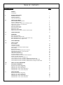
SECTION
DESCRIPTION PAGE
I. GENERAL
Specifications 1
II. INSTRUCTIONS SECTION
Installation Instructions 2
Operation Instructions 4
Preventative Maintenance 5
III. SERVICE PROCEDURES
Rinse Head/Wash Head Assemblies 6
Timer for 10 Dishmachines 7
Function of Switches, Circuit Breaker & Indicating Lights 8
Replacement of Switches in Control Panel 8
Thermostat Adjustment 9
Rinse Tank Heater System 10
Wash Tank Heater System 11
Water Level Control 12
Water Level Control (APRB) 13
Replacing Seal and Ceramic on Wash and Rinse Pumps 14
IV. TROUBLESHOOTING 15
V. DIMENSIONS
Model 10A (No Booster) 18
Model 10AB/APRB (Standard Unit) 19
Model 10AB/APRB 4SH (4” Shorter Hood/9” Shorter Leg) 20
Model 10AB/APRB 5HH (5” Higher Hood) 21
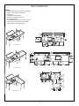
VI. TABLE DIMENSIONS 22
VII. PARTS SECTION
10A Assembly 23
10AB/APRB Assembly 24
Control Box Assembly 25
Ordering Replacement Wire/Conduit & FIttings 27
Tub Assembly 29
Bottom View Assembly 31
Wash Tank Cross View/Tub to Booster Connection 33
10AB/APRB Rinse Booster & Associated Parts 34
Pump & Motor Assembly 35
Thermostat Housing Assembly 36
Incoming Plumbing Assemblies 37
Solenoid Valve Repair Kit / Vacuum Breaker Repair Kit 38
Hood & Associated Assemblies 39
Vacuum Breaker/Connector Assemblies 10A 41
Vacuum Breaker/Connector Assemblies 10AB/APRB Standard & 5HH 42
Vacuum Breaker/Connector Assemblies 10AB/APRB 4SH (Before S/N 45973) 42
Vacuum Breaker/Connector Assemblies 10AB/APRB 4SH (Starting with S/N 45973) 43
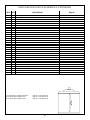
VIII. PARTS LIST FOR 10 DISHMACINES 44
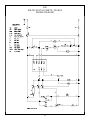
IX. ELECTRICAL SCHEMATICS
10A 208 - 220 V, 60 HZ, single phase 46
10AB 208 - 220 V, 60 HZ, single phase 46
10AB 208 - 220 V, 60 HZ, three phase 46
10AB/APRB 208 - 220 V, 60 HZ, single phase 46
10AB/APRB 208 - 220 V, 60 HZ, three phase 46
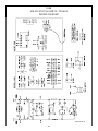
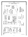
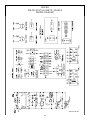
X. WIRING DIAGRAMS
10A 208 - 220 V, 60 HZ, single phase 47
10AB 208 - 220 V, 60 HZ, single phase 48
10AB 208 - 220 V, 60 HZ, three phase 49
10AB/APRB 208 - 220 V, 60 HZ, single phase 50
10AB/APRB 208 - 220 V, 60 HZ, three phase 51
TABLE OF CONTENTS
i

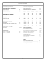
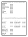
PERFORMANCE/CAPABILITIES
OPERATING CAPACITY (RACKS/HOUR)
RACKS PER HOUR 45
DISHES PER HOUR 950
GLASSES PER HOUR 950
OPERATING CYCLE (SECONDS)
WASH TIME 60
RINSE TIME 10
TOTAL CYCLE TIME 72
TANK CAPACITY (GALLONS)
WASH TANK 4.5
BOOSTER TANK (10AB and 10APRB ONLY) 3.0
PUMP CAPACITY (GALLONS)
WASH PUMP 70 GPM
TEMPERATURES
WASH---°F (MINIMUM) 150
RINSE---°F (MINIMUM) 180
ELECTRICAL REQUIREMENTS
WASH PUMP MOTOR HP 1/2
RINSE PUMP MOTOR HP (APRB ONLY) 1/2
MODEL VOLTS HERTZ PHASE AMPS
10A 208 60 1 8.23
10A 220 60 1 8.23
10AB 208 60 1 38.8
10AB 208 60 3 25.6
10AB 220 60 1 37.2
10AB 220 60 3 24.6
10APRB 208 60 1 43.4
10APRB 208 60 3 30.2
10APRB 220 60 1 41.8
10APRB 220 60 3 29.2
WATER REQUIREMENTS
INLET TEMPERATURE (10A) 180°F
INLET TEMPERATURE (10AB and 10APRB) 140°F
WATER LINE SIZE I.P.S. (Minimum) 1/2”
DRAIN LINE SIZE I.D (Minimum) 1 1/2”
GALLONS PER HOUR 58
FLOW PRESSURE P.S.I. (Optimum) 20
FLOW RATE GPM 7.8
RACKS
Dish (17 1/2” Diameter Round) 1
Glass and Silverware (17 1/2” Diameter Round) 1
Four Compartment Silverware 1
SPECIFICATIONS
1

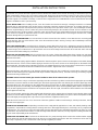
Jackson MSC Inc. provides technical support for all of the dishmachines detailed in this manual. We strongly recommend that you refer
to this manual before making a call to our technical support staff. Please have this manual with you when you call so that our staff can
refer you, if necessary, to the proper page. Technical support is available from 8:00 a.m. to 5:00 p.m. (EST), Monday through Friday.
Technical support is not available on holidays. Contact technical support toll free at 1-888-800-5672. Please remember that technical
support is available for service personnel only.
VISUAL INSPECTION: Before installing the unit, check the container and machine for damage. A damaged container is an indicator
that there may be some damage to the machine. If there is damage to both the container and machine, do not throw away the con-
tainer. The dishmachine has been inspected and packed at the factory and is expected to arrive to you in new, undamaged condition.
However, rough handling by carriers or others may result in there being damage to the unit while in transit. If such a situation occurs,
do not return the unit to Jackson; instead, contact the carrier and ask them to send a representative to the site to inspect the damage
to the unit and to complete an inspection report. You must contact the carrier within 48 hours of receiving the machine. Also, contact
the dealer through which you purchased the unit.
UNPACKING THE DISHMACHINE: Once the machine has been removed from the container, ensure that there are no missing parts
from the machine. This may not be obvious at first. If it is discovered that an item is missing, contact Jackson immediately to have the
missing item shipped to you.
LEVEL THE DISHMACHINE: The dishmachine is designed to operate while being level. This is important to prevent any damage to
the machine during operation and to ensure the best results when washing ware. The unit comes with adjustable bullet feet, which can
be turned using a pair of channel locks or by hand if the unit can be raised safely. Ensure that the unit is level from side to side and
from front to back before making any connections.
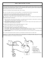
INSTALLING THE DISHMACHINE: With the machine base set in place, lift the table (with proper flange cutout) over and above
machine so that vertical flange on table cutout fits down inside of machine tub and horizontal flange on machine tub fits up tight against
underside of the table.
Ease vacuum breaker piping supplied with the dishmachine down through the square cutout in the backsplash of the table (directly
behind the machine). Connect vacuum breaker piping to machine. The top union connects to its matching half on the bottom of the
rinse booster tank. The bottom union of the piping connects to an adapter pipe which, in turn connects to the solenoid valve. The arrows
on the solenoid valve indicate the direction of water flow to the machine. Tighten both of the connections.
Adjust machine base until small hole (1 7/8” diameter) behind large flange hole, lines up with hole in support block of machine. Insert
internal vacuum breaker pipe into support block with large end down and pinned end up. It should set in snug, the retaining ring will
prevent it from being inserted too far.
WARNING: Internal vacuum breaker pipe must be installed or there will be a hazard to the operator.
Make sure there are two “O-rings” on the lower support pipe near the end of the ring. Lift the hood and hood support pipe up over table
and machine to clear the internal vacuum breaker pipe. Slide hood support pipe down over internal pipe and work support pipe down
into support block hole. The locating pin in the support block will insure proper line up. While holding the support pipe, start tightening
nut by hand to prevent cross threading. It should tighten considerable by hand. Then continue tightening with a wrench. It may be nec-
essary to work support pipe back and forth to seat nut properly. When the nut is tight, it should force flat the stainless steel and rubber
washers tight to the table top.
Attach vacuum breaker support pipe clamp (supplied with dishmachine) to the support pipe and external vacuum breaker piping. Slide
up about 12” from the table and tighten securely. Position cover plate (supplied with table) over square cutout in backsplash on table
so that it fits tightly around piping then snap in the four nylon fasteners (supplied) to hold in place.
Rotate the hood to insure it is free, if not, check level of machine, tightness of table to machine flange, centering of machine, level of
table and hood support pipe.
PLUMBING THE DISHMACHINE: All plumbing connections must comply with all applicable local, state, and national plumbing codes.
The plumber is responsible for ensuring that the incoming water line is thoroughly flushed prior to connecting it to any component of
the dishmachine. It is necessary to remove all foreign debris from the water line that may potentially get trapped in the valves or cause
an obstruction. Any valves that are fouled as a result of foreign matter left in the water line, and any expenses resulting from this foul-
ing, are not the responsibility of the manufacturer.
CONNECTING THE DRAIN LINE: The drain for the dishmachine is a gravity discharge drain. Remove the overflow strainer stopper
from the tub and the unit will drain itself. There must also be an air gap between the machine drain line and the floor sink or drain. If a
grease trap is required by code, it should have a flow capacity of 5 gallons per minute.
INSTALLATION INSTRUCTIONS
2

WATER SUPPLY CONNECTION: Ensure that you have read the section entitled “PLUMBING THE DISHMACHINE” above before pro-
ceeding. Install the water supply line (3/4” pipe size minimum) to the end of the Y-strainer. It is recommended that a water shut-off valve
be installed in the water line between the main supply and the machine to allow access for service. The water supply line is to be capa-
ble of 25 PSI “flow” pressure at the recommended temperature indicated on the data plate. In areas where the water pressure fluctu-
ates or is greater than the recommended pressure, it is suggested that a water pressure regulator be installed. The Model 10 does not
come with water a pressure regulator as standard equipment.
Do not confuse static pressure with flow pressure. Static pressure is the line pressure in a “no flow” condition (all valves and services
are closed). Flow pressure is the pressure in the fill line when the fill valve is opened during the cycle.
It is also recommended that a shock absorber (not supplied with the dishmachine) be installed in the incoming water line. This prevents
line hammer (hydraulic shock), induced by the solenoid valve as it operates, from causing damage to the equipment.
PLUMBING CHECK: Slowly turn on the water supply to the machine after the incoming fill line and the drain line have been installed.
Check for any leaks and repair as required. All leaks must be repaired prior to placing the machine in operation.
ELECTRICAL POWER CONNECTION: Electrical and grounding connections must comply with the applicable portions of the National
Electrical Code ANSI/NFPA 70 (latest edition) and/or other electrical codes.
Disconnect electrical power supply and place a tag at the disconnect switch to indicate that you are working on the circuit.
Refer to the data plate for machine operating requirements, machine voltage, total amperage load and serial number.
To install the incoming power lines, run the power lines through the hole located in the bottom of the control box to the terminal board
inside. This board is accessible by removing the lower cover plate on the control box. Attach lines (L1and L2 (L3 for three phase)) on
the terminal block at the lower front right corner. There is no neutral wire on this machine. There is a grounding lug inside the control
box on the bottom left. Be sure all connections made are tightened properly.
It is recommended that “DE-OX” or another similar anti-oxidation agent be used on all power connections.
VOLTAGE CHECK: Ensure that the power switch is in the OFF position and apply power to the dishmachine. Check the incoming
power at the terminal block and ensure it corresponds to the voltage listed on the data plate. If not, contact a qualified service agency
to examine the problem. Do not run the dishmachine if the voltage is too high or too low. Shut off the service breaker and mark it as
being for the dishmachine. Advise all proper personnel of any problems and of the location of the service breaker. Replace the front
kick panel and tighten down the screws.
INSTALLATION INSTRUCTIONS (Cont.)
3

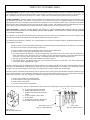
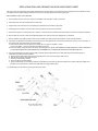
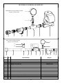
PREPARATION:
1. Ensure that the pump intake strainer (1) and basket overflow
strainer (2) are inserted and tight.
2. Ensure that the wash and rinse arms are installed and secure.
3. Remove all solid wastes in order to avoid obstructing filters,
drain and wash and rinse arms.
4. Ware that is encrusted with soil should be presoaked prior to
being placed in the machine.
5. When placing dishes into the racks, do not allow them to lean
on each other.
6. Place the glasses upside down in the open rack. With the model
10 series, a four compartment silverware rack is supplied. Place
silver in compartment rack loosely not allowing it to mix with other
silverware of the same nature. Place the compartment rack in the
open rack and wash with the cups and glasses.
DAILY MACHINE PREPARATION: Refer to the section entitled
“PREPARATION” at the top of this page and follow the instructions
there. Afterwards, check that all of the chemical levels are correct
and/or that there is plenty of detergent available for the expected
workload.
WARM-UP CYCLE: At the beginning of each work day, a warm up
cycle will need to be performed. Close the hood (3). Turn on the
master switch (4). Raise the fill switch (5) until the machine is filled
to the top of the basket overflow strainer (2.) Once the proper
water level has been reached, turn on the heater switch (6).
Observe the temperature gauges, the rinse temperature should
rise to a specified level of 180°F within five minutes if the incom-
ing water to the booster tank is 140°F. The wash heater will take
longer to reach 150°F as the element is designed for maintaining
temperature, not heating. Once the proper temperature has been
reached, with the hood closed, turn on the manual wash switch.
You should hear the water being pumped as it strikes the top of
the hood. Turn off the manual wash switch. The dishmachine is
now ready to proceed with washing of the dishes.
WARE PREPARATION: Proper preparation of ware will help
ensure good results and less re-washes. If not done properly,
ware may not come out clean and the efficiency of the dishma-
chine will be reduced. It is important to remember that a dishma-
chine is not a garbage disposal and that throwing unscraped dish-
es into the machine will defeat the purpose altogether of washing
the ware. Scraps should be removed from ware prior to being
loaded into a rack. Pre-rinsing and pre-soaking are good ideas,
especially for silverware and casserole dishes. Place cups and
glasses upside down in racks so that they do not hold water dur-
ing the cycle. The dishmachine is meant not only to clean, but to
sanitize as well, to destroy all of the bacteria that could be harm-
ful to human beings. In order to do this, ware must be properly
prepared prior to being placed in the machine.
WASHING A RACK OF WARE: To wash a rack, open the hood
completely (being careful for hot water that may drip from the top
of the hood), manually load detergent into the wash chamber, or if
automatic detergent dispenser is used, follow the manufacturers
instructions. Slide the rack of dishes into the dishmachine. Close
the hood. Start the automatic wash and rinse cycle of the dishma-
chine by flipping the start switch (7) either up or down (NOTE: The
start switch, is a three position switch. Up = Start, Center = Off,
Down = Start) the indicating light (8) will come on at the start of the
cycle. When the light goes off, the cycle is complete. Open the
hood, remove the rack of clean dishes to air dry. Repeat the cycle
by adding another rack of soiled dishes, adding the detergent,
close hood and flip start switch (8) in opposite direction.
SHUT DOWN AND CLEANING: At the end of meal time, shut off
the dishmachine by placing the start switch in center position and
turn heat switch off. Drain the dishmachine by removing the over-
flow strainer. Remove the pump intake strainer after water has
drained. Clean both strainers. Clean the inside of the unit. Clean
wash head, upper and lower rinse arms and replace the clean
strainers. Replace all removed parts. The machine is now ready
for refilling and operation.
OPERATION INSTRUCTIONS
4

Proper maintenance of you Jackson dishmachine will insure optimum service with a minimum of down time.
1. To delime the booster tank.
a. Remove the support pipe nut and lift the whole hood assembly away from the unit.
b. Loosen the fitting going into bottom side of booster tank.
c. Drain approximately 2 to 3 cups out of the tank.
d. Pour 1 to 2 cups of delimer into the hood support block opening, after tightening the booster tank union.
e. Replace the hood assembly.
f. Turn on the heat switch for 30 minutes.
g. Fill the machine with water.
h. Turn on manual wash switch and allow the unit to run for about 20 minutes.
i. Empty the machine and refill at least twice.
2. To remove all lime and corrosion deposits.
a. Fill the machine with wash water as would ordinarily be done for washing.
b. Open the door and place one cup or less of deliming compound into the water. (Be sure to follow their directions if they vary
from these being given) which is available from your detergent supplier. Read and follow the label instructions.
c. Turn on the manual wash switch and allow to wash for five minutes.
d. Open the door and examine the interior. All lime should be removed and parts should be shiny. If not, allow to wash for a
longer period.
e. After the interior is clean, empty the wash water be removing overflow strainer.
f. Replace the overflow strainer. Refill machine and allow to run for two minutes, then again drain the wash reservoir.
g. Refill as it is ready for regular operation.
3. Clean strainers.
a. Clean around overflow and pump intake strainer holes.
b. Clean around pump intake (a toothbrush makes a good cleaning tool).
4. Clean Y-strainer on the incoming water line. (Water to the machine must be turned off for this operation.)
a. Remove the plug and clean the strainer.
5. Clean rinse tubes.
a. Remove the end plugs on the lower and upper rinse arms.
b. Clean all rinse tubes with the special brush provided.
c. If spray holes in the rinse tubes are clogged, they may be cleaned with a pointed tool.
6. Clean the wash head assembly.
a. If the spray jets are plugged, use a pointed tool to dislodge and flush with water.
b. If lodged items still remain in the wash tubes, remove the wash assembly by first removing the rinse assembly.
c. Clean the assembly at the sink by flushing water through the spray jets.
d. Reinstall the wash and rinse assemblies.
7. Clean any deposits which may have built up on exterior moving parts.
PREVENTATIVE MAINTENANCE
5

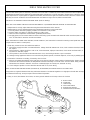
1. Turn master switch to off position.
2. Open hood and drain machine by lifting overflow strainer.
3. When empty, replace overflow strainer.
4. Remove the pin holding the rinse feed pipe and remove the feed pipe and rinse head assembly.
5. Locate the allen head set screw in wash head cap, insert allen wrench and loosen screw by turning counter clockwise.
6. Turn the wash head cap counter clockwise until the cap is removed and put the cap in a safe place.
7. Carefully remove the 1/4” stainless steel ball bearings and place in a container. Take special care to prevent any from falling through
the wash tube base for these will fall into the motor impeller. If any should fall into this area, the motor will have to be removed to retrieve
the ball bearings. If any should drop in the machine, you will be able to locate and retrieve these if you left the overflow strainer in as
suggested in step #3 above.
8. Lift and remove the small manifold with the short tubes. Put in a safe place.
9. Carefully remove the 1/4” stainless steel ball bearings and place in a container.
10. Lift and remove the large manifold with the long tubes. Put in a safe place.
11. The lower fixed race may be left in place.
12. Clean the ball bearings by soaking in a deliming solution.
13. The ball bearing race ways may be cleaned by either brushing with deliming solution or gently clean by rubbing with fine sandpa-
per or emery cloth.
14. Rinse the ball bearings and manifolds thoroughly.
15. To reassemble, first, fill the lower race way to capacity with the 1/4” ball bearings then remove one. This will give proper movement
needed during rotation of assembly.
16. Replace the lower large manifold and fill the race way fully with the bearings and then remove one.
17. Replace the upper small manifold and fill the race way fully with the bearings and then remove one.
18. Replace the wash cap by turning clockwise onto the center shaft and finger tighten.
19. Turn the wash cap counter clockwise by a 1/4 turn and tighten the allen set screw.
20. Rotate the manifolds in opposite directions, see if they rotate freely. A rule of thumb, is to select the longest tube in the bottom
manifold and make sure it moves up and down at least 1/8” and no more than a 1/4”.
21. Replace the rinse feed pipe and rinse head assembly. Replace the pin through the rinse feed casting and rinse feed pipe.
22. Close the hood doors and refill the dishwasher.
23. Run through several cycles and recheck the wash manifolds for easy movement. Adjust if necessary.
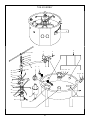
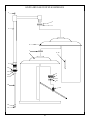
RINSE HEAD / WASH HEAD ASSEMBLIES
6
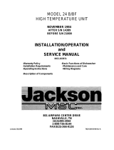
Rinse Arm Assembly
Rinse Feed Pipe Weldment
1/4” S/S Ball Bearings Qty. 11
1/4” S/S Ball Bearings Qty. 23
1/4” S/S Ball Bearings Qty. 23
Wash Head Cap
Small Manifold Wash Arm
Casting, Wash Head Bottom
Locknut, 1/4”-20 S/S
Hex w/ Nylon Insert
Wash Head Base
Set Screw, 10-24 x 1/2”
Bolt, 1/4”-20 x 2 3/4” S/S Hex Head
Large Manifold Wash Arm
Rinse Feed Casting
Rinse Feed Casting Gasket
Threaded Shaft

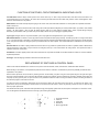
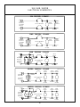
General Description: The timer is a self-contained (frame mounted) timer of the repeating cycle type. It is mounted on the control panel
of the control box, to control the automatic functions of the machine. It consists of a clock motor which operates on 60 cycle AC, 220
VAC. In addition to the clock motor, the timer also contains a driven cam arrangement which operates three microswitches.
Principle of Operation: The timer controls various operations of the dishmachine as per the wiring diagrams for each machine, how-
ever, the timing cycle and the microswitches are the same for each model. The time for one complete revolution of the cam shaft is
approximately 150 seconds, allowing two wash and two rinse operations for each complete revolution of the cam shaft. The microswitch
nearest the timer motor is the hold circuit and uses both the NO and NC contacts. The middle microswitch controls the wash and uses
the NO contact. The switch farthest away from the timer motor controls the rinse and uses just the NC contact.
Service Instructions: CAUTION: ALWAYS REMOVE THE POWER TO THE MACHINE BEFORE WORKING ON THE CONTROL
PANEL OR WHILE SERVICING THE COMPONENTS ON THE SWITCH PANEL. ALL ELECTRICAL CHECKS SHOULD BE MADE
BY QUALIFIED PERSONNEL.
Timer operation can be observed after removing the control panel from the control box by loosening the four screws holding it. Hang
the control panel using the two right hand screws with the back side of the panel outward.
If it is determined that the timer is defective, it is recommended that a new timer be installed. However, limited field maintenance can
be accomplished as follows:
A frozen contact on a microswitch will be indicated by one function being executed all the time or the absence of a click when
the switch arm is actuated. The microswitch is replaced by:
1. Remove all wires from the timer, properly tag them to assure proper replacement.
2. Remove the two screws which hold the timer to the control panel.
3. One screw holds the microswitches, cams and actuating arms in the frame. This screw is seen on the side opposite the
motor. Remove this screw. NOTE: Be sure to note which cam goes with which microswitch. Cam nearest timer motor has
1/2 raised, cam center, larger depressed areas, cam farthest from timer motor, smallest depressed areas.
4. The unit can now be taken apart and the defective microswitch replaced.
5. Reassemble. NOTE: The flanges on the cams are such that they only mesh in one direction. The shorter flange on the
cams always points toward the drive motor.
The timers cam drive system is equipped with a clutch to enable one to view the operations of the cams and microswitches. Remove
power to the machine BEFORE touching the timer. Rotate the cams by turning with fingers; cam will turn in one direction only. Do not
force them. As cams actuate switches, listen for the click of the switch or test the switches with an ohm-meter.
A defective motor is indicated by the fact that the cams do not rotate or the machine does not perform the automatic operations or per-
forms a specific part of the cycle continuously, but works okay on manual. Remember, the timer motor is controlled by the start switch
and the hold microswitch, check this complete circuit before changing the motor. The motor is replaced by:
1. Remove motor leads from connection points.
2. Remove the two screws which hold the motor.
3. Replace with the new motor.
4. Re-connect motor leads to proper points.
NOTE: It may be necessary to remove complete timer to replace motor; if so, follow steps 1 and 2 for removing the microswitches.
TIMER FOR 10 DISHMACHINES
7
A. To upper right terminal start switch.
B. To lower right terminal start switch.
C. To right-central terminal manual wash
switch.
D. To upper terminal of rinse switch.
E. To #5 terminal.
F. Shorting bar or jumpers connected to
all three timer switches, this terminal.
Timer Switch
Mfg. No.: 5945-306-02-00
Timer Motor, 220V
Mfg. No.: 5945-306-06-00
Timer, 220V
Mfg. No.: 5945-303-19-00
COM
NC
NO
E
A
B
C
D
F (on rear)

FUNCTION OF SWITCHES, CIRCUIT BREAKER & INDICATING LIGHTS
Circuit Breaker: Rated 15 amps, controls power to the control circuit only, I.E. timer, relays, solenoid valve, water level control and motors. The
circuit breaker does not cut off power in the control box at incoming terminal board and rinse heater relay contacts. Power is still applied to them
when the circuit breaker is in "off' position.
Master Switch: The switch interrupts all power going to the control circuit, this means that all switches on control panel are inoperable until master
switch is turned "on".
Start Switch: This switch controls the timer motor through two circuits (see electrical diagram) it is a three-position switch, up position = start, middle
position = off, down position = start. To start, flip switch toggle in either up or down position; indicating light in center of panel will light verifying
automatic cycle has started. After cycle ends and you are ready to start a new cycle, flip toggle to opposite position.
Cycle Light: This light comes on only when automatic cycle is in progress and extinguishes when cycle is complete.
Manual Wash Switch: The switch is used to by-pass the timer and operate the wash pump manually. The wash pump will run as long as this switch
is "on". The prime purpose of this switch is to extend the wash period for extremely soiled dished before putting them through the normal automatic
cycle. It may also be used as an emergency back-up should the timer ever fail to operate. The required wash time is indicated on the control panel
(front).
Rinse/Fill Switch: This switch is spring loaded and must be held in its up position to operate. When the switch is operated, water is allowed to fill
machine through the rinse heads. It may be used as an emergency back-up in case of timer failure tor rinsing dishes. The required rinse time is
indicated on the front control panel.
Heat Switch: This switch applies power to the heat circuits which are composed of automatic control devices that turn heaters on and off to maintain
required temperatures.
Heat Light: This indicating light remains lit all the time the heat switch is on.
REPLACEMENT OF SWITCHES IN CONTROL PANEL
There are five switches installed in the control box cover panel. These are the start, master, manual wash, rinse/fill and heater switches.
Before working on the machine, it is important that power be turned off at the customer's circuit breaker to prevent the possibility of electrical shock,
trip breaker to "off" position.
Remove control panel from the control box by removing the four screws holding it in place. Hang the control panel using the two right hand upper
and lower screw receptacles on the control box with backside of panel facing outward. The five switches are mounted in individual round holes with
a keyway. By using a pair of pliers, or open end wrench, it is possible to loosen the inside nut enough to allow the outside nut holding the switch to
be removed by fingers. Push switch out of hole.
If a switch is found to be defective, replacement can be achieved by placing the new switch next to the old one. To make the new switch is not
upside down, line up with the keyways. Transfer wires one at a time to the new switch. If this is not practical, pull wires off, one at a time and tag
them for proper replacement.
Put switches back into panel, make sure switch protrudes through panel properly, tighten both nuts, and replace control panel on control box. Power
can now be applied to the dishmachine and run through cycles checking all operations.
1. Connection terminals
2. Inside nut
3. Panel plate
4. Outside nut
5. Bar or toggle handle

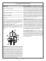
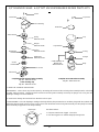
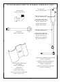
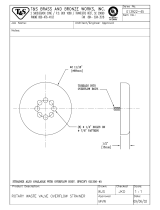
The thermostat can be adjusted by turning screw #1 (see diagram) on the thermostat housing cover. (Remember the preset setting i n
case the problems are elsewhere in the control circuit.) A clockwise rotation is used to obtain a lower temperature setting and a coun-
terclockwise rotation is used to obtain a higher temperature setting. A 1/8 turn of screw #1 changes the temperature approximately 15
degrees F. If screw #1 is turned all the way to its stop in either direction; adjust screw #2 as follows. DO NOT TOUCH THE SCREW
SEALED WITH RED PAINT! When adjusting screw #2, power should be disconnected during adjustment.
Set screw #1 so that it can be turned equal distances in either direction, then:
.....if screw #1 stopped while turning in CW direction, turn screw #2 3/4 turn in CW direction.
.....if screw #1 stopped while turning in CCW direction, turn screw #2 3/4 turn in CCW direction.
This will bring the thermostat to approximately the same setting obtained where screw #1 stopped. Check the preset temperature set-
ting before attempting any further adjustments. Use screw #1 for any further adjustments.
THERMOSTAT ADJUSTMENT
9
Thermostats can be ordered by using the following numbers:
Rinse Thermostat Mfg. No.: 5930-510-02-00
Wash Thermostat Mfg. No.: 5930-510-01-00
Screw #2
Screw #1

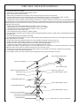
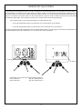
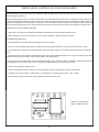
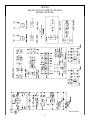
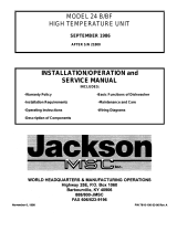
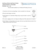
The rinse tank heater system is electrically connected in the circuit and is controlled by a heat switch (mounted on the front panel) and
a thermostat (mounted near the right front leg underneath) which activates the coil on the heat relay, mounted in the control box. When
higher temperature is required, power is applied to the heaters (mounted on the right end of built in boosters) when the contacts of the
heat relay are closed. Should the rinse tank thermometer read either too high or too low, follow checkout below.
CHECKOUT OF HEATER SYSTEM FOR RINSE TANK (Refer to drawing)
NOTE: THE FOLLOWING CHECKOUT SHOULD BE DONE BY A QUALIFIED SERVICE PERSON OR ELECTRICIAN.
1. If temperature is too high, adjust thermostat using thermostat instructions in this manual.
2. If temperature is too low, adjust thermostat using thermostat instructions in this manual then:
a. Turn off power to machine by tripping customer circuit breaker to “off” position.
b. Remove lower cover plate on control box (held by a single screw).
c. Make sure rinse temperature is below 180°F (preferably about 140°F).
d. Re-apply power, turn on master switch and observe heat relay (2 pole mounted at the lower left inside control box) letter “C” fig-
ure 1 as heat switch is turned on and off several times.
NOTE: ELECTRICAL POWER STILL APPLIED, SO BE CAREFUL. (See instructions in manual for removing control panel front. Refer
to replacement of switch in control panel.)
1. If heat relay contacts do not close: With heat switch on:
a. Check power supply at Position 1 on terminal board X. Voltage should be 208-230 VAC. If not, check customer’s breaker, if defec-
tive, replace.
b. Check position 2, voltage should be 0 volts. If not, check thermostat, adjust per instructions, check master and heat switch, if
any items are defective, replace.
c. Check position 3, there should be 208-230 Volts there. If not, check wiring for breaks or poor connections.
d. If voltage is being applied to Positions 1 and 3 and the relay doesn’t operate, it should be replaced, coil on relay is probably open.
2. To determine if elements are working, if heat relay does not close:
a. There is an insulated movable bar on the heat relay across the top of the two contacts. With an insulated probe, depress the bar
and observe the rinse thermometer, the temperature should rise noticeably in a minute or two. If it move VERY slowly, it would
indicate that one element is defective. If it moves consistently higher at a steady rate, elements are okay.
b. Check voltage at position 4. There should be 208-230 Volts. If not, check wiring.
NOTE: A CHECK WITH AN AMP PROBE (POSITION E), IF AVAILABLE, WOULD BE HELPFUL AT THIS POINT.
Clamp probe on single wire between heat relay and heater elements. The elements together on a single phase should draw 30 amps,
one element will draw only 10 amps. Replace element if found inoperative.
3. If relay is closed, but elements do not heat, use same general methods used in step 2 above for checkout.
RINSE TANK HEATER SYSTEM
10
B
A
C
3
1
X
2
L1
L2
E
D D
D
6
19
A - Heater Switch
B - Thermostat
C - Heater Relay
D - Rinse Tank Heaters
E - Amprobe Test Position
X - Terminal Board (9 terminals)

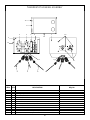
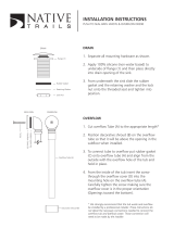
The wash tank heater control system is electrically connected in the circuit to operate on 208-230 Volts. The heat circuit is controlled
by a heat switch (mounted right front panel), water level control (mounted top inside control box), and thermostat (mounted right front
leg underneath). When higher temperature is required, power is applied to the heater element through above controls. Should the wash
tank thermometer read too high or too low, follow checkout below.
CHECKOUT OF HEATER SYSTEM FOR WASH TANK (Refer to drawing)
NOTE: THE FOLLOWING CHECKOUT SHOULD BE DONE BY A QUALIFIED SERVICE PERSON OR ELECTRICIAN.
1. Ready the machine for normal dishwashing operation with the wash tank water at proper level.
2. If temperature is too high, adjust thermostat using thermostat instructions in this manual.
3. If temperature is too low, adjust thermostat using thermostat instructions in this manual then:
NOTE: ELECTRICAL POWER STILL APPLIED, SO BE CAREFUL. (See instructions in manual for removing control panel front. Refer
to replacement of switch in control panel.)
a. With circuit breaker, master switch and heat switch on, check power to machine at position 1, terminal board “X” should read
208-230 Volts, if not, check customer’s circuit breaker, if defective, replace.
b. Wash temperature should be 130°F or less to proceed.
c. Observe water level control, letter “D”. Turn hat switch on and off several timers. Relay and contact points (inside clear case on
heat water level control) should move back and forth.
AA If water level control relay doesn’t close, (contact points don’t move in “c” above.
1. Refer to page on Water Level Control’s function and checkout.
BB If water level control relay does close, proceed with heat switch on:
1. Check voltage at position 1 on terminal board “X”. Voltage is 208-230 Volts.
2. Check position 2, there should be no voltage. If there is voltage, then adjust thermostat (refer to page on Thermostat Adjusting).
3. Check position 3, voltage should be 208-230 Volts. If not, check wiring for loose connections or a break.
4. Temperature should rise slowly, a check with an amprobe would indicate if the element is drawing the correct amperage. Replace
element if defective.
NOTE: A CHECK WITH AN AMP PROBE (POSITION E), IF AVAILABLE, WOULD BE HELPFUL AT THIS POINT.
Clamp probe on a single wire between the thermostat and wash heater element. The element should draw 3 amps. If it does not and
everything above checked out okay, replace the element. This wash element is used to maintain wash water temperature so tempera-
ture rise will be extremely slow - do not depend on this indication.
WASH TANK HEATER SYSTEM
11
D
2
1
3
E
E
F
B
C
A
X
6
19
A - Heater Switch
B - Thermostat
C - Wash Tank Heater
D - Water Level Control
E - Amprobe Test Position
F - Heater Overload
(hi-limit) on newer units.
X - Terminal Board (9 terminals)

This water level control is used on this machine in conjunction with a sensor, master switch, thermostat all of which help control the
action of the wash tank heater. The wash heater water level control is energized when the master switch is turned on.
When the water level decreases in the wash tank, the sensor (probe) sends a signal to the control which deactivates the Plug-in relay
(located on the control circuit board). When the relay deactivates, one set of its contacts return to a normally open position. The ther-
mostat and wash heater are connected in series with these contacts and at this time de-energizes the wash tank heat circuit (thermo-
stat & wash heaters). When the proper water level is restored the relay reactivates and closes the normally open contacts to energize
the wash-heat circuit. Note: The master & heat switch must be on and the wash tub full to the probe level for the wash-heat circuit to
work.
SYMPTOMS OF LEVEL CONTROL FAILURE:
1. Wash-heat circuit not energized by control. (Wash temperature not maintained by heater.)
2. Wash heater stays on with machine master and heat switch on yet no water in wash tub.
PROCEED WITH CHECKOUT:
1. Remove power to machine by turning circuit breaker to its “OFF” position.
2. Remove the 4 screws holding the control panel on the control box. Remove panel and attach to one side of control box with 2 screws.
3. Locate wash-heat water level control board and disconnect wires going to terminals marked C & H. Mark and insulate wires for
replacement.
4. Re-apply power to machine. With an insulated jumper wire, touch jumper between terminals C & H, relay in clear plastic cube should
activate as wire touched to terminals, observe relay contacts, they should pull in.
5. If relay operates, the control can be deemed operational and other causes should be explored. EXAMPLE: Wash element (open
ore shorted) thermostat is defective or needs adjustment. See thermostat page for checkout.
6. If relay does not operate, replace control to see voltage is being applied to L1 - L2 marked on control.
7. In any case, always locate sensor (probe) inside wash tub and clean off all deposits (instruct customer, this should be done on a
weekly basis.
8. Other checks can be made using the wash tank heater system checkout shown on another page.
9. Remove power to machine and replace wires that were removed in the steps above.
WATER LEVEL CONTROL
12
Sensor, Lundy Probe

The water control is used on this machine in conjunction with a sensing probe, to detect the water level in the rinse tank, and to con-
trol the automatic refilling of it.
When the water level decreases as the rinse pump starts to push water through the rinse tubes, the probe then sends a signal to the
control which deactivates the Plug-in relay (located on the control circuit board). When the relay deactivates, its contacts return to a
normally closed position. The solenoid valve is connected in series with these contacts and at this time energizes to allow water to refill
the rinse tank to the proper level. Then the relay activates and opens the normally closed contacts to deactivate the solenoid valve.
SYMPTOMS OF LEVEL CONTROL FAILURE:
1. Water level in rinse tank is not maintained, indicated by diminishing rinse spray halfway through its cycle.
2. Water continues to run at the end of the rinse cycle or water continues to spray out of the rinse tubes.
PROCEED WITH CHECKOUT
1. Remove power to machine by turning circuit breaker to its “off” position.
2. Remove 4 screws holding control panel on control box. Remove panel and attach to one side of control box with 2 screws.
3. Locate water level control board and disconnect wires going to terminals marked C & H. Mark and insulated wires for correct place-
ment.
4. Re-apply power to machine. With an insulated jumper wire, touch jumper between terminals C & H, relay in clear plastic cube should
activate as wire touched to terminals, observe relay contacts, they should pull in.
5. If relay operates, the control can be deemed operational and other causes should be explored. EXAMPLE: Solenoid valve not func-
tioning properly, loose or broken wires in circuit, sensing probe malfunctioning, or loose green ground wire.
6. If relay does not operate, replace control.
7. Remove sensing probe from rinse tank and clean any deposits that may have built up causing it to malfunction.
8. If solenoid valve does not open or remains open, see instructions on separate page to check, clean or repair.
9. Remove power to machine and replace wires that were removed in above steps.
WATER LEVEL CONTROL (AS USED ON AN APRB)
13
Water Level Control Board
Mfg. No.: 6680-200-01-19

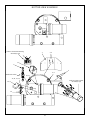
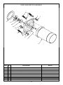
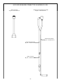
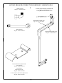
REPLACING SEAL AND CERAMIC ON WASH AND RINSE PUMPS
The pump is part of the total motor-pump system and utilizes one seal and ceramic to prevent the pump from leaking around the impeller and shaft.
One gasket is used to prevent leakage in between the pump and mounting plate and the machine pump plate.
REPLACEMENT of SEAL and/or CERAMIC.
1. Remove power source to machine by turning circuit breaker to its off position on side of control box.
2. Drain machine by removing overflow strainer in wash tank.
3. Support motor, and remove the four nuts holding the pump/motor to the machine's pump plate.
4. Carefully pull motor outward, move from side to side as required to remove from the machine.
5. Set motor and pump on a sturdy stand close to machine or remove wires and conduit to allow motor/pump to be moved to a better work position.
6. Remove dust cap over end of motor shaft (opposite impeller end). This can be done by wedging with a screw driver.
7. Remove impeller. Hold shaft by inserting screw driver in slotted end of shaft and unscrew impeller in counter clockwise direction.
8. The ceramic Is embedded in the impeller and normally does not need replacement, but it should be checked for cracks or a worn out surface. If
the ceramic does need replacement, proceed as follows.
a. With a pointed, flat tool, work the ceramic and rubber cap out of groove in impeller. b. Clean
groove of all residue. c. Apply a small amount of adhesive in groove.
d. Press new ceramic gently into groove with rubber cap leading the way. (NOTE: THE CERAMIC HAS ONE SIDE THAT IS HAS A GROOVE IN
IT. THIS SIDE SHOULD BE FACING DOWN INTO THE RUBBER CAP. THE SMOOTH SURFACE SHOULD BE FACING UP).
9. The seal is embedded in the pump mounting plate and usually will need replacement when water leaks around the motor shaft area. If
replacement is required proceed as follows.
a. Remove the four bolts holding the pump mounting plate to the motor, must done with an alien wrench.
b. Slide mounting plate up off of shaft and motor.
c. Press seal out of housing carefully.
d. Clean hole where seal was installed.
e. Apply a small amount of non-hardening sealant to the backside of seal. Insert new seal with a seal driver to prevent ruffling the edges of the
seal. Never use a screwdriver or similar tool to alternately force edge of seal in place.
10. Reassemble pump and motor by reversing the above procedure.

Problem: Nothing on the machine operates.
1. No voltage to the dishmachine. Check to see if the customer’s fuse has blown or the circuit breaker has tripped. Replace or reset.
2. Machine circuit breaker tripped or turned off. Turn on or reset.
3. Voltage to machine low or circuit to machine broken. Contact your electrician and/or power company for repair.
Problem: Machine will not fill with electrical power applied, even though other components work. (AB Model)
1. Water hand valve off. Turn hand valve on.
2. Master switch not on or faulty. Turn on or replace.
3. Fill switch faulty or loose wire connection. Replace switch or wire or connection terminal.
4. Solenoid valve does not operate. See instructions page concerning the solenoid valve.
5. Y-Strainer is clogged. Turn water to machine off, remove plug and strainer screen, clean and replace.
Problem: Machine will not fill with electrical power applied even though other components work. (APRB Model)
1. Water hand valve off. Turn hand valve on.
2. Master switch not on or faulty. Turn on or replace.
3. Fill switch faulty or loose wire connection. Replace switch or wire or connection terminal.
4. Rinse motor not operating. Check connection and voltage to motor repair or replace as necessary.
5. Water level control does not maintain the water level in the rinse tank. See instruction page concerning the water level control for
APRB Models.
6. Solenoid valve does not operate. See instructions page concerning the solenoid valve.
7. Y-Strainer is clogged. Turn water to machine off, remove plug and strainer screen, clean and replace.
Problem: Machine fills slowly and/or rinse is weak.
1. Low water pressure. Check water pressure by first, turning the heat and master switch off. Next, empty the wash tub. Then turn the
master switch on, and as you push up the fill switch, time the seconds it takes to fill the machine to the top of the overflow tube. It should
be 35 seconds. Any more than 5 seconds longer indicates the water supply and pressure and insufficient.
2. Rinse head assemblies limed up or clogged with other deposits. Clean rinse head tubes by removing end plugs and push the clean-
ing brush though to clean.
Problem: Rinse water runs continuously with power on.
1. Rinse switch sluggish or faulty. Replace.
2. Solenoid valve dirty or faulty. See special instructions page concerning the solenoid valve.
3. Water level control faulty. (APRB Models only) See special instructions page concerning the water level control for APRB Models.
4. Rinse tank probe coated. (APRB Models only) Remove and clean probe then replace.
5. Breather tube plugged or bent closed. (APRB Model only) Clean or replace tube.
Problem: Rinse water runs with no electrical power applied to the solenoid (master switch is off).
1. Water pressure excessive. Check the pressure gauge during flow period, it should read 20 PSI. If it is excessive, a pressure reduc-
er can reduce the pressure.
2. Solenoid valve diaphragm breather hole clogged. See instructions page concerning the solenoid valve.
Problem: Rinse water temperature too low (less than 180°F).
1. Incoming water temperature under required 140°F. Check incoming water temperature by first turning off heat switch, then drain the
machine wash tub. Next, with the master switch, push the fill switch up and hold 1 and a half minutes (90 seconds). Release the fill
switch and read the rinse thermometer. The temperature should read 140°F or higher. If it is not this temperature, then the customer’s
supply water heater temperature must be adjusted to provide proper temperature.
2. Heat switch, relay thermostat or elements faulty. See instructions page concerning Rinse Tank heater system.
Problem: Rinse water temperature too hot (over 200°F) and water may dribble out of the rinse heads from time to time.
1. Thermostat needs adjustment or is faulty. See instructions page concerning thermostat adjustment.
2. Heat relay contacts welded or held shut. Remove power and alter cause, holding contacts closed or replace relay if needed.
TROUBLESHOOTING SECTION
15

Problem: Vacuum breaker leaks.
1. Limed up. To disassemble: Use flat jaw wrench or channel locks. Remove the poppet. Clean poppet, top, and body. Reassemble
parts removed.
2. Faulty. Replace needed parts or whole vacuum breaker.
Problem: Wash arms spray water but do not rotate.
1. Wash cap adjusted too tight. See instructions page concerning removal of rinse and wash head assemblies.
2. Race ways where ball bearings rotate rough or full of food particles. See instructions page concerning removal of rinse and wash
head assemblies while apart. Clean race way with emery cloth or fine sandpaper. Soak ball bearings in lime dissolving solution, rinse
and dry with a lint free towel.
Problem: Wash water only spray up and out of tubes a couple of inches.
1. Overflow strainer clogged or pump intake strainer clogged. Remove overflow strainer. When the wash tub is empty, reach in open-
ing (where the overflow was) and remove the pump intake strainer and clean thoroughly.
2. Pump impeller worn or broken (only after many years of use). See instructions page concerning seal and ceramic on wash and
rinse pump for removal and inspection of impeller.
3. Obstruction in pump chute or wash manifold. Follow #2 above to remove pump then check chamber and manifold.
Problem: Wash motor or rinse motor (APRB Model only) does not operate.
1. Faulty. Checkout and remove for motor repair if necessary.
Problem: Wash water temperature too low (below 150°F).
1. Rinse water temperature too low. Raise rinse water temperature to a max of 196°F using instruction page concerning thermostat
adjustment.
2. Thermometer faulty. Check thermometer and replace if necessary.
3. Water level control faulty. See instruction page concerning water level control (wash heat circuit).
4. Wash heater faulty. See instruction page concerning wash tank heater system.
5. Thermostat faulty. See instruction page concerning wash tank heater system.
Problem: Water flow near rinse tank indicating leak.
1. Hood support pipe does not have two (2) O-rings below the support nut. The hood must be removed to check and replace the o-
rings, but be sure the leak is coming from there before proceeding.
2. Hood support block (center back of wash tub) is leaking. Tighten the screws from the inside of the tub. Sometimes you can remove
the screws one at a time and fill the holes with a non-hardening, food zone safe sealant and replace screws.
3. Hood support nut not down tight against washer, gasket, and table. Tighten down.
Problem: Hood scrapes when opened.
1. Machine not level. Make sure rim of dishwasher tight up against table all around by loosening or tightening bullet feet on machine
and table.
2. Hood not centered. Remove upper spray head assembly and insert a 1/2” by 9” or more nipple. With pressure on nipple, force hood
away from where it rubs.
3. Hood too low. Raise arm by using pressure on hood arm upward.
4. Inside adjustment nut too loose or tight. Turn washer lock tab up and rotate spanner nut to tighten or loosen then bend tab to lock
spanner in place.
Problem: Water sprays from lower rinse arms after end of each cycle.
1. Water pressure too high holding solenoid valve open. Check and install pressure reducer if necessary.
2. Water temperature set too high in rinse tank. See instructions page concerning thermostat adjustment.
3. Internal vacuum breaker pipe not in hood support arm. See illustration on page concerning hood support pipe.
Problem: Indicator lights do not glow at any time.
1. Lights faulty or poor connection. Replace or correct connection.
TROUBLESHOOTING SECTION (CONTINUED)
16

Problem: None of the automatic functions work (wash, rinse).
1. Start switch faulty. Check switch. Replace if necessary, see instructions page concerning replacement of switches in control panel.
2. Wire connections poor. Correct the connection.
3. Timer rinse or wash microswitch faulty. See instructions page concerning timer and motor.
Problem: Rinse does not work when manual rinse fill switch operated, but does work during automatic cycle.
1. Normally open contact on rinse fill switch faulty. See instruction page concerning replacement of switches in control panel.
2. Wire connection poor. Correct the connection.
Problem: Wash does not work on automatic cycle, but does on manual wash.
1. Normally closed contacts on wash switch faulty. See instruction page concerning replacement of switches in control panel.
2. Wire connections poor. Correct the connection.
3. Timer rinse or wash microswitch faulty. See instructions page concerning timer and motor.
Problem: Wash does not work when manual wash switch operated but does work during the automatic cycle.
1. Normally open contact on wash switch faulty. See instruction page concerning replacement of switches in control panel.
2. Wire connection poor. Correct the connection.
Problem: When master switch is turned on either it washes continuously or rinses continuously.
1. Timer motor faulty and cams are not turning holding it in the mode it is in. See instruction page on the timer & timer motor.
Problem: Wash tub water level continuously lowers.
1. Large overflow strainer not seated properly. Remove and insert with a slight twisting action.
2. O-ring in drain fitting is missing. Replace. See illustration on page concerning overflow strainer and drain o-ring.
3. Deposit build up on drain fitting or O-ring. Clean.
4. Bottom of overflow strainer (conical end of tube) bent out of shape. Replace strainer.
TROUBLESHOOTING SECTION (CONTINUED)
17

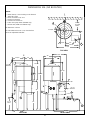
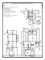
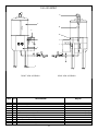
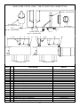
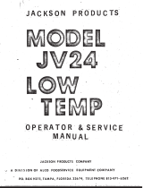
DIMENSIONS 10A (NO BOOSTER)
18
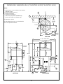
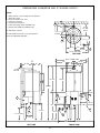
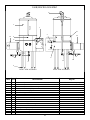
NOTES:
A - Water inlet 1/2” I.P.S. Plumbing can be directed
either left or right.
B - Drain connection 1 1/2” I.P.S.
C - Electrical connection
D - Clearance for dishes 14”
E - Power rinse pump motor (10APRB only)
F - Booster tank (10AB and 10APRB only)
All dimensions in inches.
All vertical dimensions are +/- 1/2” from the floor
due to the adjustable bullet feet.
9”
14 7/8”
TO THE
WALL
13”
5 1/4”
1 13/16”
16 1/2”
18”
16 1/2”
19 1/4”
28 3/4”
19”
12” TO
INLET
11”
13 1/2”
15 1/2”
4”
58 1/4”
34”
2 3/4”
21”
27 1/2”
C
C
B
B
D
A
A
TOP VIEW
LEFT SIDE
FRONT VIEW
CIRCUIT
BREAKER
VACUUM
BREAKER
C
L
C
L
B
22 1/4”
Page is loading ...
Page is loading ...
Page is loading ...
Page is loading ...
Page is loading ...
Page is loading ...
Page is loading ...
Page is loading ...
Page is loading ...
Page is loading ...
Page is loading ...
Page is loading ...
Page is loading ...
Page is loading ...
Page is loading ...
Page is loading ...
Page is loading ...
Page is loading ...
Page is loading ...
Page is loading ...
Page is loading ...
Page is loading ...
Page is loading ...
Page is loading ...
Page is loading ...
Page is loading ...
Page is loading ...
Page is loading ...
Page is loading ...
Page is loading ...
Page is loading ...
Page is loading ...
Page is loading ...
-
 1
1
-
 2
2
-
 3
3
-
 4
4
-
 5
5
-
 6
6
-
 7
7
-
 8
8
-
 9
9
-
 10
10
-
 11
11
-
 12
12
-
 13
13
-
 14
14
-
 15
15
-
 16
16
-
 17
17
-
 18
18
-
 19
19
-
 20
20
-
 21
21
-
 22
22
-
 23
23
-
 24
24
-
 25
25
-
 26
26
-
 27
27
-
 28
28
-
 29
29
-
 30
30
-
 31
31
-
 32
32
-
 33
33
-
 34
34
-
 35
35
-
 36
36
-
 37
37
-
 38
38
-
 39
39
-
 40
40
-
 41
41
-
 42
42
-
 43
43
-
 44
44
-
 45
45
-
 46
46
-
 47
47
-
 48
48
-
 49
49
-
 50
50
-
 51
51
-
 52
52
-
 53
53


Jackson / Dalton Dishwasher 10AB-4SH User manual
- Type
- User manual
Ask a question and I''ll find the answer in the document
Finding information in a document is now easier with AI
Related papers
-
 Jackson / Dalton Dishwasher HIGHER HOOD OPTION User manual
-
 Jackson / Dalton Dishwasher 10-4SH User manual
-
 Jackson / Dalton Dishwasher WW-1 User manual
-
Jackson / Dalton Dishwasher 10U User manual
-
 Jackson / Dalton Dishwasher 24P-NSU User manual
-
 Jackson / Dalton Dishwasher 44CERPW User manual
-
 Jackson / Dalton Dishwasher 24B-SN1 User manual
-
 Jackson / Dalton Dishwasher TempstarHH-208/230 User manual
-
 Jackson / Dalton Dishwasher 24BF-SN2 User manual
-
 Jackson / Dalton Dishwasher JV24 User manual


Other documents
-
 T & S Brass & Bronze Works B-0491-01 Datasheet
-
 T&S BRASS 013922-45 Datasheet
-
Samlexpower DUAL RACK PLATE for SEC-POWER SUPPLIES Owner's manual
-
 Newport Brass 120/VB Installation guide
-
Newport Brass 121/10B Installation guide
-
 Native Trails Kitchen & Bath DR290-BN Installation guide
-
Holley 12-126 Operating instructions
-
Apollo Conbraco 5900602 Installation guide
-
Westbrass D206B-01 Installation guide
-
Jackson 24 F Installation, Operation And Service Manual


