Newport Brass 3-2062BP/65 Installation guide

Category
Sanitary ware
Type
Installation guide
INSTALLATION INSTRUCTIONS
Pressure Balancing Valve
Valve Body No. 1-685
as used with Tub and Shower Fittings
Description
This valve is precision engineered to provide satisfactory performance provided it is installed and operated in
accordance with our recommendations contained in these instructions. In order to fully enjoy the comfort,
safety and the reliability of this valve, be certain to familiarize yourself with these instructions.
Operation
The pressure balancing cartridge contained in this valve
compensates for pressure fluctuations in the water sup-
ply system through a spool and sleeve pressure balancing
mechanism. The outlet temperature will change by no
more than a mere ±2°F (1°C) with a 50% drop in either
the hot or cold water pressure. Even if the cold water
pressure fails completely, the anti-scald design will reduce
the flow rate to a safe level ensuring reliable protection
against scalding. The built-in check valves prevent cross
flow between the hot and cold supplies.
Illustration 1
1-685
Floor line
Tub / Shower Installation Shower / Hand shower Installation
Page 1 of 5
NWP-1-685
Note: This valve is deisnged to fit in a 2" X 4" stud wall (or thicker) installation. Use stem extension
kit #1-384 (sold seperately) if valve installed is too far away from the finished wall.
B
EFORE YOU BEGIN
On tiled wall surfaces, grouting must be either flush or raised for proper sealing of the cover plate.
IMPORTANT: It is not necessary to remove the cartridge from the valve during NORMAL soldering operations using
propane-butane gas. DO NOT USE OXYGEN-ACETYLENE. When soldering connections, do not solder within
4” of valve port. Do not use excessive heat. Open the stop valves when soldering inlets.
It is recommended that the pipes be flushed clean prior to installation, in order to avoid any future problems.
Ensure that the stop ring is properly installed, see below, otherwise a user could potentially disengage the cartridge
with minimal force to external handle. This would cause the valve to fail, losing control of flow & temperature.
Make sure valve is securely fastened to studs. Be sure to remove trim items, handles, escutcheons and plates before
installation. Wrap carefully and store until finished wall is completed.
Install the valve by positioning the 1/2” shower outlet in the up position. If installing showerhead & hand shower config-
uration, plumb showerhead from tub port (T) and hand shower from shower port (S). Finished wall must be within
dimensions shown in illustration 2. To test pipe joints, pressurize both hot and cold inlets.
Installing Trim
Thread plastic upper link into finished post. Insert assembled post onto end of diverter stem, then slide finished sleeve
over attached items and screw sleeve into diverter housing. Place coverplate on valve stem while sliding diverter trim
through rubber grommet. Screw on escutcheon trim and mark all-thread nipple where excess needs to be cut off.
(NOTE: For stem to be fully seated into cartridge, all-thread nipple and locking nut must be tightly secured against
retaining plate.) Place handle on stem. Measure excess between escutcheon and handle base. Remove handle and cut
previously measured excess from end of stem. Secure handle into place by tightening the handle setscrew or tightening
the bonnet depending on handle construction.Screw diverter knob onto finished post. (Refer to Illustrations 2 and 3.)
Illustration 2
Face of stud
Escutcheon
Broach stem
Cover plate
Handle
NOTE: Dimensions shown are from the inlet ports to the finished wall.
Grommet
Diverter knob
Diverter stem
Mud Guard
Face of stud
Face of Finished Wall
2-7/8 TO 3-1/2
Mud Guard
All thread
nipple
Page 2 of 5
Generic Cover plate and
Handle shown(not included)
NWP-1-685
4” hole for valve
Illustration 3
Page 3 of 5
Diverter stem
plastic upper link
finished post
finished sleeve
diverter knob
Generic diverter trim shown-not included
NWP-1-685
ASM 1-281
Setting the Temperature Limit Stop
This valve has an upper temperature limit stop , which can allow desired and safe hot water temperature
(recommended maximum is 110°F). This stop may be adjusted once the valve is installed.
Before making this adjustment, run water with the valve turned to the hot setting. If the water temperature
is too high in this position, then perform the following adjustments:
1. Remove the trim (handle, escutcheon and cover).
2. Remove the all-thread nipple, (item 7), hex nut (item 8) and stem plate (item 6).
3. Remove the broach stem (item 5) and the limit stop (item 4).
4. Close the valve by turning the cartridge stem clockwise until it stops, (Illustration 4).
5. From the CLOSED position, rotate the cartridge stem counter-clockwise until the desired temperature is
achieved.(Illustration 5).
6. Place the limit stop (item 4) on the cartridge stem against the stop block (Illustration 6). Rotate several
times to make sure the stop is at the desired temperature setting.
7. Install the broach stem (item 5), stem plate (item 6), all thread nipple (item 7) and hex nut
(item8).(NOTE : For broach stem to be fully seated onto cartridge, the all thread nipple (item 7) and hex
nut (item 8) must be tightly secured against the retaining plate).
Illustration 4
Illustration 5
LIMIT STOP HITS
STOP BLOCK AT
HIGHEST
DESIRED TEM-
PARATURE
Illustration 6
Page 4 of 5
NWP-1-685
* WARNING - Never try to stop dripping by applying extreme force or overtightening the handle.
MALFUNCTION CAUSE REMEDY
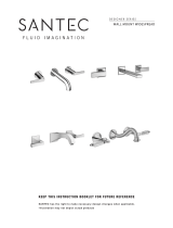
Opening immediately to hot water.
Hot and cold water supplies have been
connected in reverse. Rotate cartridge 180degrees. (Illustration 7)
Water drips after shutting off the
valve. Residual water in valve and piping. Allow approximately 3-8 minutes to drain.*
O-ring seal on the inlet of the cartridge is
faulty or seat assembly is damaged.
Check the O-ring & seat for cuts or over-
heating damage during installation.
Replace if necessary.
Water insufficiently hot.
Adjustable handle position stop incorrectly
set.
Refer to the instruction on “Setting
Temperature Limit Stop”.
Valve body too deep into wall.
The measured rough in or finished wall sur-
face is incorrect. Reset the valve.
Diverter will not stay on during show-
er.
Not enough backpressure between shower-
head and diverter valve.
Ensure a 2.0 GPM flow restrictor is mount-
ed at the shower head.
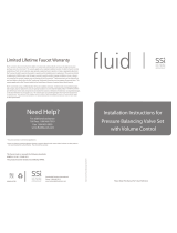
No or low flow of hot or cold water.
Either the hot or cold side is not fully pres-
surized.
Verify that the service stops for both the
hot and cold are fully open (turn counter-
clockwise) and pressurized. Illustration 8.
Debris caught inside the inlet of the car-
tridge.
Remove the cartridge (See Page 3). If
debris is lodged in the inlet of the cartridge.
The debris can be removed with a straight-
ened paper clip or fine wire. Gently insert
the wire and move it in a circular motion to
dislodge any debris.
2001 CARNEGIE AVE, SANTA ANA CA 92705
(949) 417-5207
WWW.NEWPORTBRASS.COM
Page 5 of 5
Illustration 7
Illustration 8
06/18/2018
NWP-1-685
EN-3632
Rev E
  • Page 1 1
  • Page 2 2
  • Page 3 3
  • Page 4 4
  • Page 5 5

Newport Brass 3-2062BP/65 Installation guide

Category
Sanitary ware
Type
Installation guide

Ask a question and I''ll find the answer in the document

Finding information in a document is now easier with AI