Page is loading ...

Installation Instructions for
Pressure Balancing Valve Set
Please Keep This Manual For Future Reference
Need Help?
For additional assistance
Toll Free: 1 800 460 7019
Fax: 1 604 430 5050
Volume Control Pressure Balancing Valve/2018/V4
www.fluidfaucets.com
TM
Limited Lifetime Faucet Warranty
fluid
™
warrants its faucets to be free from defects in material and workmanship for as long as the original consumer
purchaser owns his or her home.* This warranty applies only in original installation location. If a defect is found in normal
residential use, fluid
™
will, at its election, repair, provide a replacement part or product, or make an appropriate adjustment.
fluid
™
reserves the right to examine the product in question and its installation prior to replacement. This warranty is limited
to replacement of defective parts only. Damage to a product caused by accident, improper installation, misuse, or abuse is
not covered by this warranty. Improper care and cleaning will void the warranty.** Replacement parts can be obtained from
your local dealer or directly from the fluid
™
warehouse. Dated proof of purchase must accompany all warranty claims. This
warranty applies only to fluid
™
faucets installed in the United States of America, Canada or Mexico (North America).
labor charges, repair or replacement costs are expressly excluded. In no event shall the liability of fluid
™
exceed the purchase
price of the faucet. Some states and provinces do not allow the exclusion or limitation of incidental or consequential damages,
™
fluid dealer
or sales representative.
This faucet meets or exceeds the following standards:
ASME A112.18.1 / CSA B125.1
* Two year warranty on commercial applications.
** Never use cleaners containing abrasive cleansers, ammonia, bleach, acids, waxes, alcohol, solvents or other products
not recommended for surface finishes. This will void the warranty.
IAPMO LISTED
with Volume Control
Sustainable Solutions International
www.SustainableSolutions.com
Phone: 1 800 460 7019
fluid
™
recommends using a certified plumber for faucet installation and repair. Incidental and consequential damages,
so the above limitation may not apply to you. This warranty gives you specific legal rights which vary from state/province
to state/province. If you find any such problem with your product, please immediately contact your nearest
This product has been tested and certified by IAPMO.

Recommended Installation Layout
for Pressure B alancing Valve with Diverter F1000B
Recommended Installation Layout
for Pressure Balancing Valve without Diverter F1001B
21
Tub and Hand Shower
Tub and Fixed Shower
Hand Shower Only
Fixed Shower Only
Fixed Shower and Hand Shower
Tub Spout Only

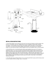
1. Shut off cold and hot water supplies.
4. Install pressure balancing valve body(#1) so that the surface of FINISHED wall is between the MIN
and the MAX mark on the mud guard(#6).
3. This valve must be installed with the cold inlet port(A, marked in blue color) on the right and the
hot inlet port(B, marked in red color) on the left. Also ensure that the arrow on the mud guard(#6)
and the word “UP” or “fluid” on the valve body (#1) point upwards and use the bubble level(#7) for
leveling reference.
5 . Connect the valve body(#1) to water supplies using proper fittings (copper tubing or PEX).
(A) is the cold inlet port and (B) is the hot inlet port.
5.1 For 1/2” Copper Tube Soldering Connections: Solder water supply tube to valve body(#1)
NOTE: Prior to soldering, you must unscrew the retaining nut(#3) and remove the cartridge(#2-1), the
anti-back flow block(#2-3) and both integral stops(#5). Also remove diverter(#9A) by using the supplied
wrench(#11). Avoid soldering excessively at high temperature.
5.2 For 1/2” IPS Thread Connections: Apply Teflon tape or other thread sealant onto threaded ends
and connect water.
As shown on page 2, F1000B valve is used to divert water between two fixtures, such as a fixed or hand shower
and a tub spout. Port D is the priority port. Connect the fixture you wish water to flow to initially to Port D.
1/2” Copper pipe must be used for Port D (do not use PEX). Port C is the diverter port. Connect the diverting
fixture to Port C using either 1/2” Copper or PEX. To switch the water from the tub spout to the shower, simply
pull the diverter stem(#9A).
Valve Installation Instructions
Tools Required for Installation
Adjustable Wrench
Screw Driver
Soldering Equipment
Adjusting Maximum Temperature
FOR PRESSURE BALANCING VALVE WITH DIVERTER F1000B:
F1000B
Pressure Balancing Valve with Diverter, used for Tub and Shower installation
F1001B / F1001B-PEX
Pressure Balancing Valve without Diverter, used for Tub Only or Shower Only installation
with a supplied hex cap (#9B) or it can be used in tub and shower installation when a tub
spout with a diverter is used.
FOR PRESSURE BALANCING VALVE WITHOUT DIVERTER F1001B:
Teflon Tape
Used for Tub Only or Shower Only installation with a supplied hex cap(#9B) or it can be used in tub and shower
installation when a tub spout with an integral diverter is used.
2. Make sure to use the enclosed Cutout Template to open the wall properly.
4
Caution: The valve is preset at the factory test at maximum. To adjust, please follow these instructions:
Remove red max temperature adjusting ring from the cartridge(#2-1). Turn the red ring clockwise to adjust
the max temperature to the desired setting. Reassemble and test until the desired setting is achieved.
3
The drawing shows typical measure-
ments from the floor. In order to assure
proper function, piping from the bottom
port D of valve to tub spout outlet MUST
be 1/2” nominal copper pipe. Do not use
PEX FOR THIS CONNECTION.
Approx 20"
[508mm]
Tub Spout
Cover Plate
Approx 42" for use with tub
[1067mm]
Approx 48" for shower only
[1219mm]
Shower Head
Approx 78"-81"
[1980-2057mm]
Finished Floor
NOTE: To protect the valve, keep mud guard (#6) on during installation. Remove only when ready to install
trim parts.
Valve to Tub Spout:
Must use 1/2”
nominal copper
pipe
Socket Wrench (supplied)

Trim Installation InstructionsTools Required for Installation
Allen Wrench
Adjustable Wrench
Screw Driver
Teflon Tape
5 6
1. Valve Trim, Cover Plate and Handle
F1000B
F1001B / F1001B-PEX
17
17
Use the Recommended Installation Layout on pages 1 and 2 to plan your trim
installation. If the valve has been installed too deeply into the wall and the trim
cover plate can not be installed on the finished wall, please contact the store where
product was purchased or a fluid sales representative for a valve extension kit.
For F1000B Valve Trim, Cover Plate and Handle Installation
6. Install handle(#17) onto cartridge stem(#2). Tighten set screw(#8) with the supplied
3/32”(2.5mm) Allen wrench(#10). Push in plug(#9).
3. Screw diverter knob(#16) onto diverter stem(#6A) and use the supplied 1.5mm
Allen wrench(#14) to secure it with a set screw(#15).
4. Apply a small bead of silicone at four corners of the backside of the square cover
plate(#7) OR peel white tape off seal gasket at the backside of round or soft corner
square cover plate.
5. Slide cover plate(#7) over diverter housing(#13) and sleeve tube(#12) and gently
press cover plate(#7) against the finished wall.
1. Slide sleeve tube (#12) over cartridge housing(#4), then screw cap(#11) onto
retaining nut(#3) and tighten it with an adjustable wrench, being careful not to
scratch the finish.
2. Slide diverter housing(#13) onto diverter stem (#6A) and secure it onto valve
body(#1) with an adjustable wrench, being careful not to scratch the finish.
For F1001B / F1001B-PEX Valve Trim, Cover Plate and Handle Installation
4. Install handle(#17) onto cartridge stem(#2). Tighten set screw(#8) with the supplied
3/32”(2.5mm) Allen wrench(#10). Push in plug(#9).
2. Apply a small bead of silicone at four corners of the backside of the square cover
plate(#7) OR peel white tape off seal gasket at the backside of round or soft corner
square cover plate.
3. Slide cover plate(#7) over sleeve tube(#12) and gently press cover plate(#7) against
the finished wall.
1. Slide sleeve tube(#12) over cartridge housing(#4), then screw cap(#11) onto retaining
nut(#3) and tighten it with an adjustable wrench, being careful not to scratch the
finish.

4. Thread shower head(#4) onto shower arm(#3).
Tools Required for Installation
For Fixed Showerhead Installation:
2. Slide escutcheon(#2) over shower arm(#3).
3. Apply Teflon tape onto both threads of the shower arm(#3) and screw shower
arm(#3) into 1/2”threaded elbow(#1).
For Tub Spout Installation:
1. Make sure 1/2”threaded elbow(#5) is installed securely inside the wall and is
connected to the correct outlet of the rough-in valve.
4. Secure tub spout(#8) with two set screws (#9) by using a 3/32”(2.5mm) Allen
wrench (#10).
3. Slide escutcheon(#22) over “Speed Connector”(#21).
4. Install elbow (#24) into “Speed Connector”(#21).
For Handheld Shower Installation:
2. Screw “Speed Connector”(#21) into threaded elbow(#20).
5. Use the supplied 3/32”(2.5mm) Allen wrench (#16) to secure set screw(#25).
7. Mark position of mounting bracket (#14) on the finished wall.
6. Determine the desired location of handheld shower holder (#18).
1. Make sure 1/2” threaded elbow (#20) is installed securely inside the wall and is
connected to the correct outlet of the rough-in valve.
8. Drill holes per marks and insert plastic anchors (#12) into the
finished wall.
9. Secure mounting bracket(#14) against the wall by fastening with screws(#13).
11. Insert rubber washers(#19) into the end thread fittings of flex
hose(#17).
10. Secure holder(#18) with set screws(#15) using the supplied 3/32”(2.5mm) Allen
wrench (#16).
12. Thread flex hose(#17) onto elbow (#24) and handheld shower(#11).
1. Make sure 1/2”threaded elbow(#1)is installed securely inside the wall and
is connected to the correct outlet of the rough-in valve.
Fixed Showerhead
2. Thread“Speed Connector”(#6) into threaded elbow(#5).
3. Slide back plate(#7) (if included - some models do not include back plate), and then
tub spout over“Speed Connector”(#6).
NOTE: For“Speed connector”(#6) installation details, refer to the enclosed General
Instruction of “Speed Connector”.
7 8
Tub Spout
Handheld Shower
Trim Installation Instructions
4
3
2
1
Allen Wrench
Adjustable Wrench
Screw Driver
Teflon Tape

9
10
SSI products are designed and engineered under strict quality standards. Regular
and proper care of our products will ensure years of trouble-free service.
Clean with a damp cloth and warm soapy water. Then simply rinse off and wipe dry
with a soft cloth. Do not use abrasive or harsh cleaners as they may result in finish
damage.
Care & Maintenance Instructions
For Surface Finish:
Remove the retaining nut(#3) with an adjustable wrench, being careful not to
scratch the finish. Pull out the cartridge(#2-1) and the back flow preventor block(#2-3)
together by hand. Use a small flat head screw driver to separate the block(#2-3) from
the cartridge(#2-1). Use a small round tool to push the back flow preventors(#2-2)
from the block. Rinse cartridge(#2-1) and back flow preventors(#2-2) under running
water to ensure any trapped debris has been removed. To remove mineral deposits
like Calcium, immerse cartridge(#2-1) in distilled vinegar for 30 minutes, then rinse
well with running water. Shake cartridge(#2-1) by hand and make sure that the stainless
steel pressure balancing spool at the bottom of cartridge body is freely moving inside
its casing. You should hear a “clicking” sound if the spool is moving properly. Pay
attention to the flow direction as shown in diagram and insert back flow preventors
(#2-2) into the block(#2-3). Align two stainless steel screws on the bottom surface of
cartridge(#2-1) to two holes on the block(#2-3) and push them together tightly. Align
two pins on the bottom surface of block(#2-3) to the two top holes on the valve body.
Gently push cartridge(#2-1) and block(#2-3) into place and make sure cartridge and
block are properly seated in body. If seated, the cartridge(#2-1) will not rotate. Thread
retaining nut(#3) onto the body and tighten with an anjustable wrench, being careful
again not to scratch the surface.
.
To clean your fluid Cartridge and Back Flow Preventor:
F1000B
Pressure Balancing Valve with Diverter
F1001B / F1001B-PEX
Pressure Balancing Valve without Diverter
Back low Preventor
Flow Direction
Use the supplied socket wrench(#11) and place it over the diverter stem and hex
nut(#9A). Turn the socket wrench(#11) counter-clockwise to remove the diverter
assembly(#9A). Wash the diverter assembly(#9A) with clean running water and
ensure that any trapped debris has been removed. Dry and lightly grease all rubber
seals (use only NSF approved Silicone grease). Replace the cleaned or new diverter
assembly(#9A) with the supplied socket wrench(#11).
For Pull-out Style Diverter:
To shut off cold and/or hot water going to the valve body, use a medium size flat
head screw driver to turn the metal stem of integral stop(#5) clockwise to close.
To achieve the maximum flow rate, the integral stop should be fully opened when
the metal stem is fully brought out of the hex nut by using a medium size flat head
screw driver.
For Integral Stop:
/