Page is loading ...

FORM SIG 085
Revised 6-01-18
Page 1 of 4
Pressure Balancing Valve
Shower or Tub/Shower
Installation Instructions
Notice:
These instructions do not represent step-by-step directions.
They are a pruduct supplement only to be used by a qualified and
licenced plumber.We recommend all plumbing fixtures be installed
by a professional.
SPECIFICATIONS
Minimum operating pressure 20 psi
Maximum operating pressure 125 psi
Max hot water inlet temp. 190°F
Hot and cold water inlets ½” NPT male
Shower and tub outlet ½” NPT male
Flow capacity 5 GPM / 60 psi
This valve is precision engineered to provide satisfactory performance provided it is installed and operated in accordance with
recom
-
mendations contained in these instructions. Please be sure to familiarize yourself with these instructions.
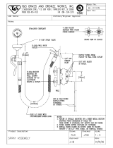
PRIOR TO STARTING:
1. FLUSH lines of debris prior to starting. Debris may clog cartridge.
2. The mud guard represents a typical hole size required to access the integral service stops and the removable
cartridge. The rough valve comes PRE-ASSEMBLED and FACTORY READY TO INSTALL.
3. Be alert that the valve body is not installed upside down. See markings on BACK of valve.
4. The screwdriver service stops should always be in the full-open position with the valve in use. They are not to be used
INLETS
6. Shower valve (Part # 18.30.061 or Part # 78.30.061) may be used for shower only or tub only. The unused port
must be capped by plumber during installation.
ROUGH-IN OF VALVE
copper sockets or 1/2” Male I.P. nipples. NOTE “UP AND DOWN” MARKINGS ON BACK OF VALVE.
CRITICAL TO PLACE MUD GUARD FLUSH WITH FINISHED WALL. FIG. 1
3. Anchor installation to bracing between studs. (Ears on the valve body can be used by removing the plastic guard OR by
anchoring the connection piping.)
DO NOT close wall until valve is tested.
wall material is installed.
6. Use only propane or butane gas when soldering. Do not use
oxygen / acetylene as extreme heat may damage internal
components. Do not solder within 4 inches of valve port. Open
stop valves when soldering inlets.
7. FOR TUB/SHOWER INSTALLATIONS: 36” must be allowed between
supply line must
Finished wall
to center of inlets/outlets
3-1/4”
6”
Finished Wall
IMPORTANT
MAKE SURE THE VALVE IS INSTALLED
FLUSH WITH FINISHED WALL AS SHOWN
MUD GAURD IS
TO PROTECT VALVE
DURING CONSTRUCTION.
REMOVE FOR
TRIM INSTALLATION.
AFCC
FINISHED WALL FLUSH
WITH THIS SURFACE
IMPORTANT
FINISHED WALL FLUSH
WITH THIS SURFACE
IMPORTANT
U
P
C
C
R
PART# 18.30.061
SHOWER ONLY VALVE
(ALSO USE FOR 78.30.061)
PART# 18.30.062
TUB / SHOWER ONLY VALVE
(ALSO USE FOR 78.30.062)
Notice:3200 spout is provided with 3/4” NPSM to1/2” NPT bushing
separately. Water sealing should be done by a licensed plumber.

FORM SIG 085
Revised 6-01-18
Page 2 of 4
!
!
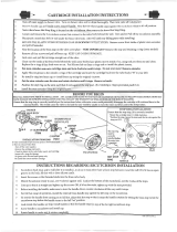
SETTING HOT LIMIT STOP
IT IS THE RESPONSIBILITY OF THE INSTALLER TO SET THE MAXIMUM OUTPUT TEMPERATURE OF THE VALVE AS SPECIFIED BY
THE AUTHORITY HAVING JURISDICTION IN ACCORDANCE WITH ASSE/ANSI 1016-2005 4.2.2 REQUIREMENTS.
thermometer or calibrated sensing device to accurately measure the outlet water temperature.
2. Turn off the water using both screw driver service stops.
3. Expose the top of the cartridge by removing the top hex cap from the valve body. FIG. 2
4. Remove the temperature ring by placing the blade of a knife into the groove and
prying it off. FIG. 3. It is not necessary to remove the inner hex nut.
5. Locate the stop tab on the bottom of the ring. The further it is re-oriented in a counter-clock
vary and water supply temperatures vary as well.
6. IMPORTANT!! BEFORE RE-ORIENTING THE RING, BE SURE THE STEM IS IN THE FULL OFF
POSITION.
maximum hot water temperature.
FIG. 2
FIG. 3
HEX CAP
TEMPERATURE
RING
1. Install extended stem and all thread onto cartridge stem. Fully seat stem onto cartridge by tightly securing all
thread nipple and locking nut onto valve. Install plate and centering nut. FIG 4a.
to extend. FIG 4b.
3. Place handle on stem and measure excess between escutcheon and handle base. Remove handle and cut
excess from end of stem using cut marks provided. FIG 4c.
4. FOR TUB/SHOWER TRIM:
REPLACEMENT PARTS:
18.30.893 Cartridge
18.30.894 Diverter Cartridge
18.30.891 16 pt. stem extension
18.30.892 20 pt. stem extension
18.30.890 All thread
FIG. 4c
Cut this distance
from end of Stem Extension
so handle sits just above
the escutcheon
Gap
Handle
Stem Extension
Diverter Handle Sleeve
Diverter Handle Stem and Sleeve
thread directly onto Valve Extension
FIG. 4a
Trim Plate
Trim Plate Centering Nut
(not used on all handle trim)
FIG. 4b
Cut All-thread Flush with
top of escutcheon
Escutcheon
All-thread
Cut
INSTALLING TRIM

FORM SIG 085
Revised 6-01-18
Page 3 of 4
HANDLE TENSION ADJUSTMENT
SIGMA offers many handles of varying sizes and weights. Each
design allows the installer to set the torque (tension) on each
valve that uses the standard assembly B through F as shown.
Part C is a loose brass O-ring that is compressed inside Part E by
tightening or loosening Part D.
REVERSING CARTRIDGE FOR BACK-TO-BACK INSTALLATIONS ONLY
allow normal operation. FIG. 5
1. Expose top of valve.
2. Loosen and remove hex cap above cartridge with wrench.
3. Remove cartridge from valve cavity.
4. Look into cavity to see upper and lower locating holes for cartridge pin on
cutaway by discharge opening).
7. Secure cartridge by tightly re-assembling the cap using wrench.
8. Re-assemble trim.
FIG. 5
Malfunction Cause Remedy
Shower control opening
through hot.
Hot and cold water supplies have been
connected in reverse.
Rotate cartridge as described in
”Back to Back Installation”
drips after shutting off
valve.
the shower head (this is normal)
Failure to close cartridge before
setting temperature ring causing
a partially opened cartridge.
Seal on the inlet of the cartridge
is faulty.
Allow approx. 3-5 min. to drain column.*
Reset the temperature ring as described on Figure 3.
Check the seal for cuts or damage and replace if necessary.
Adjustable handle position stop incor-
rectly set.
- Reset handle position.
- Check hot water source temperature setting.
cold water.
Either the hot or the cold side is not fully
pressurized.
Debris caught inside the inlets of the
cartridge.
Be sure service stops are both wide open and system
is fully pressurized.
Install stem extension kit.
Trim parts do not
operate valve correctly.
Stem and all thread not installed to
proper lengths.
or call customer service.
Trim plate will not install
wall.
Re-install valve to proper depth or call dealer for
custom trim plate.
Maintenance
The cartridge is designed for minimum maintenance in normal domestic use. If a malfunction occurs then this will
probably necessitate a complete replacement. The cartridge contains no internally serviceable parts! Contact your installer or dealer.
To Clean trim
and should never be used for cleaning decorative faucets.
Trouble Shooting - Pressure Balancing Valve

FORM SIG 085
Revised 6-01-18
Page 4 of 4
CONSUMER WARNING
CALIFORNIA PROPOSITION 65 WARNING
AMERICAN FAUCET & COATINGS CORPORATION
LIMITED PRODUCT WARRANTY
Product/Finish Warranty -
-
-
-
What we will do
What you must do:
use only. The faucets cannot be altered in any way. You must maintain and clean the faucets in accordance with the instructions
provided with the product. You must use the faucet(s) for residential use only.
How to obtain service:
American Faucet & Coatings Corporation
3280 Corporate View
Vista, CA 92081
contribute small amounts of lead to water that is allowed to stand in contact with the brass. This faucet complies with all E.P.A. regula-
tions regarding the amount of lead used in plumbing brass and solder. The amount of lead contributed by any faucet is highest when
AMERICAN
AMERICAN
What is not covered:
-
ings Corporation's printed instructions. In the case of in-the-wall installations American Faucet and Coatings Corp. will as-
sume no liability if there is no access. In no event will we be liable for labor of any kind, incidental or consequential
damages.
Many in-
(This does not include
Unless otherwise contrary to state law governing the purchase, American Faucet and Coatings Corporation's liability will not exceed the wholesale
also have other rights which vary from state to state. Some states do not allow exclusion of incidental or consequential damages, so the above
limitation may not apply to you.
LIFETIME WARRANTY ON 1/4 TURN CERAMIC DISC CARTRIDGE
hoses unless we have contacted you and have sent you an approved RGA form. All transportation charges for returned goods
must be paid by the customer.
known to the State of California to cause birth defects or other reproductive harm.
• Always run the water for a few seconds prior to use for drinking or cooking.
• Use only cold water for drinking or cooking.
/