InSinkErator F-HC3300SN User guide

Type
User guide
Instant Hot Water Dispenser
Owner’s Manual
CONTEMPORARY
ANTIQUE
TUSCAN
MODERN
Installation, Care & Use
Instalación, cuidado y uso
Installation, soin et utilisation
HWT-F1000S
HWT-HP
HWT-00
GN/HC1100
GN/HC2200
GN/HC2215
H/HC3300
1.800.558.5700
www.insinkerator.com
44704 REV B
The Emerson logo is a trademark and a service mark of Emerson Electric Co.
InSinkErator may make improvements and/or changes in the specifications at any time, in its sole discretion,
without notice or obligation and further reserves the right to change or discontinue models.
©2014 InSinkErator, a business unit of Emerson Electric Co. All Rights Reserved.
El logotipo Emerson es una marca registrada y una marca de servicio de Emerson Electric Co.
InSinkErator puede realizar mejoras y/o modificaciones en las especificaciones en cualquier momento, y bajo su exclusivo
criterio, sin previo aviso u obligación; además, se reserva el derecho de cambiar o suspender los modelos.
©2014 InSinkErator, una unidad comercial de Emerson Electric Co. Todos los derechos reservados.
Le logo Emerson est une marque de commerce et de service d'Emerson Electric Co.
InSinkErator se réserve le droit, à son entière discrétion, d’apporter en tout temps des améliorations ou des modifications
aux spécifications, et ce, sans préavis ou obligation de sa part, ou de modifier ou de supprimer des modèles.
©2014 InSinkErator, une unité commerciale d'Emerson Electric Co. Tous droits réservés.
To see a tutorial of this installation:
Para ver un tutorial de esta instalación ingrese a
Pour voir un tutoriel de cette installation
http://goo.gl/yYrfOA
A
Property Damage: Do not pinch or break copper
tubing. Do not distort the last 1 inch of tubing.
INSTALLING THE FAUCET
Unpack dispenser components.
On a firm, flat surface, care
fully
straighten the copper tubing.
NOTICE
HOW TO USE THIS INSTRUCTION MANUAL
Provides a step-by-step narrative describing the installation step, with check boxes
that can be marked as you progress through the installation.
Contains simple illustrations that provide visual instruction to support the narrative.
Important safety messages that will require your attention during the step.
These instructions are separated into main sections, indicated by numbers, and subsections,
indicated by capital letters. The manual is setup this way to allow you to take a break at any
point after completing a section or subsection without affecting the installation process.
What you’ll see in the
instruction manual:
1
2
3
Identify the model of your instant hot water dispenser and record it here:________________
1
2
A potentially hazardous situation, which, if not avoided, could result in death or serious injury.
A potentially hazardous situation, which, if not avoided, may result in minor or moderate injury.
Do not plug in the power to the hot water tank Until Step 6C. To avoid permanent damage to
the product, only operate the tank after it is filled with water.
3
We are delighted that you have chosen the InSinkErator
®
Instant Hot Water Dispenser
to be a part of your home. This unique appliance will save you time and effort in the kitchen,
and you’ll enjoy discovering new uses for it each day. That’s exactly why millions of people are
now using an InSinkErator Instant Hot Water Dispenser.
We are confident that by following our step-by-step instructions, you’ll soon be enjoying the
convenience of instant hot water.
For your satisfaction and safety, read all instructions, cautions and warnings before installing or using this instant
hot water dispenser.
This particular unit is not intended for commercial use.
Make sure that all electrical wiring and connections conform to local codes.
A standard 115-volt grounded electrical outlet is required under the sink for the dispenser’s electrical power.
The wall outlet powering your dispenser must have power supplied to it continuously.
This outlet must be fused and should not be controlled by the same wall switch that operates the disposer, unless
you have a SinkTop Switch
from InSinkErator
®
.
It is recommended that a dedicated control valve be installed on the cold water line supplying water to this system.
If you suspect elevated levels of chlorine in your water, or your water has a rusty appearance before the installation
of this unit, it is recommended to use our water filtration system.
This product contains stainless steel. The manufacturer cannot guarantee against rusty water because of the
number of factors that are involved beyond the manufacturer’s control. However, the sudden appearance of rusty
water discharged from the hot water dispenser may indicate the need for service or replacement of this product.
The use of a water filter should NOT result in the water pressure to drop below 30 psi (207kPa). If it does, this will
prevent your unit from operating properly.
Moving parts inside the tank causing a rattling noise is normal.
WHAT YOU SHOULD KNOW BEFORE YOU BEGIN
n Phillips and flat blade screwdrivers
n Pencil
n Tape measure
n Level
Equipment You May Need:
Equipment Required:
n Drill
n T-fitting
n Dedicated control valve
n Adjustable wrench
n Philips Screw Driver
n Pencil
n Tape Measure
Anchors for drywall
Hole saw
Basin wrench
Hole punch
If you intend to use the sprayer hole in your sink for your dispenser, you may need a basin wrench and a
1/8" plug or a 1/4" cap (not supplied) for the faucet spray hose line.
See Step 1B.
If you need to cut a mounting hole in your stainless steel sink, you may need a 1
1
4" - 1
1
2" hole saw made
for cutting stainless steel or a hole punch. Consult a professional if you are drilling into a surface other
than stainless steel.
WHAT YOU NEED TO GET STARTED
F-HC3300/F-H3300F-HC1100 F-GN1100
F-GN2215F-HC2215
F-GN2200F-HC2200
OVERVIEW OF A
COMPLETED SETUP
2 3
Notice is used to address practices not related to personal injury.
NOTICE
NOTICE
To see a tutorial of this installation:
http://goo.gl/yYrfOA
COMPONENTS IN THIS PACKAGE
HWT-F1000S
HWT-HP
HWT-00
(filtration system optional)
*
*
*
Filter Head
1/4" Tubes (2)
Filter Cartridge
Brass Nut/Ferrule/
Tube Insert
F-HC1100 F-GN1100
F-HC2215 F-GN2215
F-HC2200 F-GN2200
Semi-circular
Mounting Plate
Rubber O-Ring
Hex Nut
Brass Seat
(HC3300, H3300)
Hex Tool
3/4" Screws (4)
Y-Quick Connector
F-H3300
F-HC3300
Plug (1)
4
A
A
Turn off water supply.
Remove tubes from tank: At tank
top, depress gray release tab into
quick-connect fitting securing blue
or copper 1/4" tube and gently pull
line out of fitting. Pull white 7/16"
tube and clear 5/16" tube off fittings.
Remove existing faucet and continue
to page 6.
Turn off water supply.
Remove tubes from tank: At tank
top, depress gray release tab into
quick-connect fitting securing blue
tube and gently pull line out of fitting.
Pull white 7/16"
tube and clear 5/16" tube off fittings.
Remove existing tank and continue
to page 9.
Property Damage: Do not pinch or break copper
tubing. Do not distort the last 1 inch of tubing.
Property Damage: Unplug tank
before disconnecting tubing.
IF INSTALLING ONLY NEW TANK
Releas
e
Tab
1/4"
blue
7/16"
white
5/16"
clear
Release
Ring
1/4"
blue or
copper
7/16"
white
5/16"
clear
Releas
e
Tab
1/4"
blue
7/16"
white
5/16"
clear
Release
Ring
1/4"
blue or
copper
7/16"
white
5/16"
clear
IF INSTALLING ONLY NEW FAUCET
5
Brass Nut
Ferrule
Brass Insert
Wing Nut
Fiber
Washer
Brass Nut
Ferrule
Wing Nut
Fiber
Washer
1
2
3
Plastic
tube
Brass Nut
Ferrule
Brass Insert
Wing Nut
Fiber
Washer
Brass Nut
Ferrule
Wing Nut
Fiber
Washer
1
2
3
Plastic
tube
If installing BOTH new faucet and new tank, skip to page 6.
Snap-connect fitting not included. Required when replacing tank manufactured
prior to January 2006. Call the AnswerLine® 1-800-558-5700 to order.
STOP
Do not plug in the power to the hot water tank Until Step 6C. To avoid permanent
damage to the product, only operate the tank after it is filled with water.
NOTICE
NOTICE
NOTICE
To see a tutorial of this installation:
http://goo.gl/yYrfOA
Property Damage: Do not pinch or break copper
tubing. Do not distort the last 1 inch of tubing.
From under the sink, place the
semi-circular mounting plate onto
the threaded stud.
Place hex nut onto the threaded stud.
Ensure faucet head is at desired angle.
Insert screwdriver into hole on side of
hex tool (creating a “T”), and use tool
to tighten nut and secure faucet.
2
Semi-circular mounting plate should
encircle all descending tubes and
extend beyond sink hole when tight.
Ensure that the black O-ring is
properly seated in the base of the
dispenser head (the groove on the
underside of the dispenser).
Brass Nut
Ferrule
Brass Insert
Wing Nut
Fiber
Washer
Brass Nut
Ferrule
Wing Nut
Fiber
Washer
1
2
3
Plastic
tube
Brass Nut
Ferrule
Brass Insert
Wing Nut
Fiber
Washer
Brass Nut
Ferrule
Wing Nut
Fiber
Washer
1
2
3
Plastic
tube
Feed tubes down through the hole
in the sink or countertop until the
base is at rest on the sink or
countertop surface.
Brass Nut
Ferrule
Brass Insert
Wing Nut
Fiber
Washer
Brass Nut
Ferrule
Wing Nut
Fiber
Washer
1
2
3
Plastic
tube
Unpack dispenser components.
On a firm, flat surface, carefully
straighten the copper tubing.
To ease feeding of tubes through hole,
first insert blue tube with quick-connect
attachment and then insert the remaining tubes.
B
A
C
D
Make sure to use rubber O-ring
to ensure proper seal.
INSTALLING THE FAUCET - 1100/2200/2215
The wall outlet for your dispenser must have power supplied to it continuously
and must be fused. It should not be controlled by the same wall switch
that operates your disposer, unless using an InSinkErator SinkTop Switch
TM
.
PREPARATION
START HERE
Identify locations for the dispenser
faucet, tank and filter.
Check to make sure there is proper
clearance for dispenser handles to
be fully opened.
Check to make sure counter is 3"
thick or less.
Make sure there is a grounded
electrical outlet under the sink.
Turn off water supply.
If using the sink sprayer hose hole,
remove nut that connects sprayer
hose at bottom of faucet.
Using adjustable wrench, remove nut
connecting sprayer washer flange in
sprayer hole.
Plug hose opening with either a 1/8"
plug or a 1/4" cap (not supplied).
1
A
B
Brass Nut
Ferrule
Brass Insert
Wing Nut
Fiber
Washer
Brass Nut
Ferrule
Wing Nut
Fiber
Washer
1
2
3
Plastic
tube
If you have to drill through sink or
countertop, you may need to rent or purchase
the appropriate tools.
Consult a professional before drilling into
a surface other than stainless steel.
C
What if you don’t have a sprayer hole or
don’t want to use it?
Many homeowners replace the soap
dispenser in their sink with an instant
hot water dispenser.
If drilling a hole into a stainless steel
sink or counter top, you can cut a
mounting hole for the dispenser with a
hole saw for stainless steel, or you can
use a hole punch.
Required Hole Size
F-HC1100 ................2
5
8"
F-GN1100 ................3
1
4"
F-HC2200 ................2
7
8"
F-GN2200 ................3
1
2"
F-HC2215 ................2
7
8"
F-GN2215 ................3
1
2"
F-HC3300 ................2
1
2"
F-H3300 ...................2
1
2"
Required minimum from
center of hole to wall
Maximum counter thickness is 3".
F-HC1100 ................1
3
8" - 1
1
2"
F-GN1100 ................1
1
4" - 1
1
2"
F-HC2200 ................1
3
8" - 1
1
2"
F-GN2200 ................1
1
4" - 1
1
2"
F-HC2215 ................1
3
8" - 1
1
2"
F-GN2215 ................1
1
4" - 1
1
2"
F-HC3300 ................1
3
8" - 1
1
2"
F-H3300 ...................1
3
8" - 1
1
2"
6
7
An assistant may be needed to
hold the dispenser head in place while
securing the dispenser.
Brass Nut
Ferrule
Brass Insert
Wing Nut
Fiber
Washer
Brass Nut
Ferrule
Wing Nut
Fiber
Washer
1
2
3
Plastic
tube
NOTICE
To see a tutorial of this installation:
http://goo.gl/yYrfOA
Brass Nut
Ferrule
Brass Insert
Wing Nut
Fiber
Washer
Brass Nut
Ferrule
Wing Nut
Fiber
Washer
1
2
3
Plastic
tube
A
Select a spot under the sink to mount
tank vertically within reach of both
plumbing and electrical connections.
The tank should be within 16" or less
of faucet water lines and within 30"
or less of a standard grounded outlet.
While holding tank in place on
the spot selected for installation,
use a pencil to mark locations for
2 hanging screws.
Property Damage: Tank must be located
within 16" of faucet and within 30" or less
of a standard grounded outlet. DO NOT
extend plumbing or electrical lines.
3
Tank must be
mounted level
to ensure
proper operation.
Mount tank vertically in an area that allows clear-
ance on the underside of the tank for drainage, if
necessary.
DO NOT over tighten screws.
Pre-drill 1/8" pilot holes at marks.
Turn screws into pre-drilled holes,
leaving 1/4" exposed.
Hang the tank on the screws.
Tighten the screws with only
1/2 turn clockwise.
B
Screws provided are for use in wood
studs or cabinets only. Use wall anchors
(not supplied) for installation into drywall.
Leave 1/4" for
hanging tank.
Without depressing the gray button,
place the snap-connect fitting at
the end of the blue tube onto the
left fitting on the tank, pushing until it
clicks into place. (1)
Slip the flexible white 7/16" tube
over barbed steel fitting and slide
down approximately 1/2". (2)
Slip the clear 5/16" tube over the
smooth plastic fitting and slide down
approximately 1/2". (3)
Check for pinched or crimped tubes.
4
A
Property Damage: Pinched or blocked water lines
may cause damage to the dispenser tank. Check
to make sure tubes are connected properly and
are pushed down as far as possible.
Hose clamps are not needed for any
of the connections.
MOUNTING THE TANK
CONNECTING FAUCET TO TANK
Property Damage: Do not pinch or break tubing.
Do not distort the last 1 inch of tubing.
From under the sink, place the
semi-circular mounting plate onto
the threaded stud.
Place hex nut onto the threaded
stud. Ensure dispenser handle is on
preferred side and that faucet head
is at desired angle.
Insert screwdriver into hole on side
of hex tool (creating a “T”), and use
tool to tighten nut and secure faucet.
2
Semi-circular mounting plate should
encircle all descending tubes and
extend beyond sink hole when tight.
Insert rubber O-ring into groove on
brass seat.
Place brass seat, O-ring side down,
over hole in sink or countertop.
Holding brass seat in place, feed
tubes down through the hole in sink
or countertop until base touches
brass seat.
Rotate brass seat until the two
retaining studs fit into the holes on
the faucet base and base sits firmly
on brass seat.
Unpack dispenser components.
The recommended installation for
this faucet is dispenser handle on
the right.
The unique design allows the
handle to be fully functional when
placed to the right or left of faucet.
Determine preferred handle
placement before installing.
To ease feeding of tubes through hole, first
insert blue tube with quick-connect attachment
and then insert the remaining tubes.
B
A
C
D
Wetting O-ring with water prior to
inserting into brass seat helps hold
ring in place during installation.
INSTALLING THE FAUCET - 3300
8 9
(1) (2) (3)
Do not plug in the hot water tank Until Step 6C.
NOTICE
NOTICE
NOTICE
To see a tutorial of this installation:
http://goo.gl/yYrfOA
C
Scalding Hazard: The faucet dispenses near-boiling
(212ºF) water which can instantly cause scalds or
burns. Use care when operating this appliance.
Property Damage: Join remaining tube
to cold water supply only.
Turn on water supply.
Open hot water faucet to expel trapped air.
For the F-1000S and F-1000, flush
2.25 gallons through filter before use
(approximately 3 minutes). For the F-2000S
and F-2000, flush 3 gallons through filter
before use (approximately 4 minutes).
B
A
Featuring OptiPush
hot side activation with
automatic shut off and cool side Stay-On
, which
keeps the faucet open when dispensing cool water.
HC3300: To dispense instant hot water, first
press down on the faucet handle and then
push the handle backward in the direction of
the red indicator on the top of the handle.
To dispense cool water, first press down on
the faucet handle and then pull the handle
forward in the direction of the blue indicator
on the handle.
Note: Only applies when handle is mounted on
left side.
Featuring OptiPush
hot side activation with
automatic shut off.
H3300: To dispense instant hot water, first
press down on the faucet handle and then
push the handle backward in the direction of
the red indicator on the top of the handle.
6
Brass Nut
Ferrule
Brass Insert
Wing Nut
Fiber
Washer
Brass Nut
Ferrule
Wing Nut
Fiber
Washer
1
2
3
Plastic
tube
Install a T-fitting (not included) onto the cold
water supply line.
Install dedicated water control valve with 1/4"
compression fitting.
At the end of the white 1/4" tube from the filter
or quick-connector, slide the supplied brass nut
and ferrule over the tube and then push in the
brass tube insert.
Insert the white 1/4" tube into the 1/4"
compression fitting and tighten.
If the water coming from the faucet is not hot 15 minutes after the unit has been
plugged in – or for other issues related to the operation of your instant hot water
dispenser – refer to the “Troubleshooting” section on Page 17.
Brass Nut
Ferrule
Brass Insert
Wing Nut
Fiber
Washer
Brass Nut
Ferrule
Wing Nut
Fiber
Washer
1
2
3
Plastic
tube
FINAL WATER CONNECTION
Brass Nut
Ferrule
Brass Insert
Wing Nut
Fiber
Washer
Brass Nut
Ferrule
Wing Nut
Fiber
Washer
1
2
3
Plastic
tube
C
Check all connections to ensure they are tight
and that there are no leaks.
Plug in instant hot water tank.
Water will be cold at first.
Allow 12-15 minutes for water to reach
target temperature.
Gurgling or hissing is normal during the
initial heating cycle.
Property Damage: A standard grounded outlet within
30” of the dispenser is required under the sink. Do not
use an extension cord set with the dispenser.
Operating Instructions for Indulge
TM
Modern Faucets
Dispensing Hot Water
(HC3300, H3300)
Dispensing Cool Water
(HC3300)
Scalding Hazard: The faucet dispenses near-boiling
(212ºF) water which can instantly cause scalds or
burns. Use care when operating this appliance.
Property Damage: Do not extend the lines farther
than the 16” provided. Ensure tube(s) and “Y”
connector are securely fit.
Personal Injury: Do not locate filter above an outlet or other
electrical device. Install head and bracket so that connections
require no stretching, kinking or pinching of tubing.
It is normal for approximately 2 oz. of water to
discharge when filter is removed.
Property Damage: Tube runs need to form to the cabinet’s
contours to allow storage space with no sharp bends. Tubes
need clean, perpendicular, burr-free cuts to ensure a true fit.
A
Determine length of tubing required,
then cut to length making sure the cut
is perpendicular and burr-free.
Insert a white 1/4" tube into inlet side
of filter head until it stops. Press in
again to ensure a secure fit.
Insert the other white 1/4" tube into
outlet side of filter head until it stops.
Press in again to ensure a secure fit.
Separate cartridge from filter head.
Mark hole locations for filter head
and bracket in a spot that allows
for filter replacement.
Drill 1/8" starter holes and attach bracket
to wall with wood screws, turning until snug.
Insert cartridge into filter head. Top
surface of cartridge will become flush with
bottom of filter head when fully engaged.
Connect remaining white 1/4" tube to
incoming water supply line.
(See Step 6.)
Insert the copper tubes(s) from the
dispenser into “Y” quick-connector
using the plug for hot-only models.
Connect the white 1/4" tube from
the right outlet on the filter head into
the quick-connect fitting until it stops.
Press in again to ensure a secure fit.
from water
supply line
to dispenser
To remove tube(s) or plug from quick-connector,
depress the release ring and gently pull away.
From filter or
water supply line
Plug
D
5
INSTALLING FILTRATION SYSTEM
Screws provided are for use in wood
studs or cabinets only. Use wall anchors
(not supplied) for installation into drywall.
B
From water
supply line
To dispenser
10 11
From filter or
water supply line
HC1100, HC2200,
HC2215
GN1100, GN2200, GN2215,
HC3300, H3300
NOTICE
NOTICE
NOTICE
NOTICE
To see a tutorial of this installation:
http://goo.gl/yYrfOA
IMPORTANT SAFETY INFORMATION IMPORTANT SAFETY INFORMATION
Property Damage: To reduce the risk associated with property damage due to water
leakage or flooding, and to ensure optimal performance:
Read and follow Use Instructions before installation and use of this system.
Installation and use MUST comply with all state and local plumbing codes.
System Requirements (Hot Water Tank, Filtration System and Dispenser):
The flexible vent and outlet tubes must be correctly connected to the tap supplied by
the manufacturer. They must not be obstructed or connected to a normal type tap or
any other type.
Do not install on hot water supply lines. The maximum operating water temperature of
this system is 100°F (37.8°C). Attach to cold water supply only.
Do not install if water pressure exceeds 125 psi (862 kPa). If your water pressure
exceeds 80 psi (552 kPa), you must install a pressure limiting valve. Contact a
plumbing professional if you are uncertain how to check your water pressure.
Do not install where water hammer conditions may occur. If water hammer conditions
exist you must install a water hammer arrester. Contact a plumbing professional if you
are uncertain how to check for this condition.
Where a backflow prevention device is installed on a water system, a device for
controlling pressure due to thermal expansion must be installed.
Protect from freezing, shut off water supply, remove filter cartridge, drain hot water
tank and tubing when temperatures are expected to drop below 40° F (4.4° C); see
Seasonal Storage/Drainage section.
Do not use a torch or other high temperature sources near system, cartridges, plastic
fittings or plastic plumbing.
Do not install near water pipes which will be in path of a drilling tool when selecting
the position to mount the bracket.
Mount system in such a position as to prevent it from being struck by other items used
in the area of installation.
Ensure that the location and fasteners will support the weight of the system when
installed and full of water.
Ensure all tubing and fittings are secure and free of leaks.
Do not install using rigid piping. System intended for use with plastic water lines (such
as PEX tubing, PE tubing, PP tubing).
Do not install this system if any of the quick connect collets are missing from the filter
head or Y-Quick Connector. Contact an authorized InSinkErator Service agent if collets
are missing from any fittings.
For systems using two handle HC model faucets, operate only one handle at a time.
Important: Do not allow the unit to continuously boil.
Regularly inspect the system. If there are signs of water leakage, turn off the water
supply and contact an authorized InSinkErator Service agent.
A drain pan, plumbed to an appropriate drain or outtted with a leak detector, should
be used in those applications where any leakage could cause property damage.
For questions or concerns, please contact an authorized InSinkErator Service agent
(see back page for contact information).
Additional Consideration when Utilizing Filtration System:
The disposable filter cartridge MUST be replaced every 6 months, at the rated capacity
or sooner if a noticeable reduction in flow rate occurs.
Failure to replace the disposable filter cartridge at recommended intervals may lead to
reduced filter performance and cracks in the filter housing, causing water leakage or
flooding.
Protect from freezing, remove filter cartridge when temperatures are expected to drop
below 40° F (4.4° C).
Do not install systems in areas where ambient temperatures may go above
100°F (37.8°C).
Do not install in direct sunlight or outdoors.
NOTICE
Fire Hazard: To minimize possibility of fire, DO NOT store flammable items such as rags,
paper or aerosol cans near the tank. DO NOT store or use petrol or other flammable
vapors and liquids in the vicinity of this or any other appliance.
Leak Hazard: Regularly inspect dispenser and plumbing fittings for leaks, which can
cause property damage and could result in personal injury.
A steaming hot water tap, like any water heater, has a limited life and will eventually fail. To avoid possible property
damage and personal injury, this steaming hot water tap should be regularly examined for leakage and/or corrosion and
replaced when necessary. A drain pan, plumbed to an appropriate drain or outfitted with a leak detector, should be used
in those applications where any leakage could cause property damage.
n Use this water heater only for its intended use as described in this manual.
n This appliance is not intended for use by persons (including children) with reduced physical, sensory or mental
capabilities, or lack of experience and knowledge, unless they have been given supervision or instruction
concerning use of appliance by a person responsible for their safety. Children should be supervised to ensure that
they do not play with hot water tap. To reduce the risk of injury, close supervision is required when an
appliance is used near children.
n Do not operate this product if it has been or appears to be damaged in any manner or after the product
malfunctions, or is dropped. Return the complete product immediately to your retail dealer for inspection, and
if necessary, adjustment or repair.
Important: Always arrange the power cord so that it cannot come in contact with hot surfaces.
n Do not disconnect the product from the power supply by pulling on the cord.
n Do not use the product for other than its intended use as described in these instructions. The use of accessory
attachments other than those recommended by the manufacturer may cause safety hazards.
n The recommended connection may be made to an existing cold water line with a branch terminating with a shutoff
valve, a pressure relief and dual check non-return valve sited adjacent to the product.
Electric Shock Hazard: To reduce the risk of electric shock, do not immerse or expose
the product, flexible cord or plug to rain, moisture or any liquid or when standing in
or on damp or wet surfaces. If any electrical product falls into water, UNPLUG it
immediately. DO NOT REACH INTO THE WATER. Important: Prior to reconnecting to the
power supply, the product should be inspected by a qualified technician.
To reduce the risk associated with the ingestion of contaminants: Do not use with water
that is microbiologically unsafe or of unknown quality without adequate disinfection before
or after the system.
Personal Injury/Property Damage: To reduce the risk associated with hazardous
voltage due to an installer drilling through existing electric wiring in the area of
installation: Do not install near electric wiring which may be in path of a drilling tool
when selecting the position to mount the system bracket.
Also avoid the risk of drilling into water pipes which may result in property damage.
This appliance must be earthed (grounded). This steaming hot water tap is equipped with a cord that has a
grounding conductor and earth ground pin. The plug must be connected to an appropriate outlet that is properly installed
and earthed (grounded) in accordance with all local codes and ordinances. Do not modify the plug provided with the
appliance – if it will not fit the outlet, have a proper outlet installed by a qualified electrician. Check with a qualified
electrician or tradesman if you are in doubt as to whether the steaming hot water tap is properly earthed (grounded).
Electric Shock Hazard: Using an ungrounded (no earth ground) or improperly
connected appliance can result in serious injury or death from electrical shock.
To reduce the risk associated with choking: Do not allow children under 3 years of age to
have access to small parts during the installation of this product.
Personal Injury/Property Damage: This tank is a non-pressurized tank. DO NOT modify
this system. DO NOT close vent tube or connect other types of taps or valves to the tank.
Use only the InSinkErator tap supplied. Use only parts provided. Contact an authorized
InSinkErator Service agent for repairs or replacement components.
This warranty is provided by InSinkErator, a business unit of Emerson Electric Co., (“InSinkErator” or “Manufacturer” or “we” or
our” or “us”) to the original consumer owner of the InSinkErator product with which this warranty is provided (the “InSinkErator
Product”), and any subsequent owner of the residence in which the Product was originally installed (“Customer” or “you” or “your”).
InSinkErator warrants to Customer that your InSinkErator Product will be free from defects in materials and workmanship, subject
to the exclusions described below, for the “Warranty Period”, commencing on the later of: (a) the date your InSinkErator Product is
originally installed, (b) the date of purchase, or (c) the date of manufacture as identified by your InSinkErator Product serial number.
You will be required to show written documentation supporting (a) or (b). If you are unable to provide documentation supporting
either (a) or (b), the Warranty Period commencement date will be determined by Manufacturer, in its sole and absolute discretion,
based upon your InSinkErator Product serial number.
What is Covered
This warranty covers defects in materials or workmanship, subject to the exclusions below, in InSinkErator Products used by a consumer
Customer for residential use only, and includes all replacement parts and labor costs. YOUR SOLE AND EXCLUSIVE REMEDY
UNDER THIS LIMITED WARRANTY SHALL BE LIMITED TO REPAIR OR REPLACEMENT OF THE INSINKERATOR PRODUCT.
What is not Covered
This limited warranty does not extend to and expressly excludes:
Losses or damages or the inability to operate your InSinkErator Product resulting from conditions beyond the Manufacturer’s
control including, without limitation, accident, alteration, misuse, abuse, neglect, negligence (other than Manufacturer’s),
failure to install, maintain, assemble, or mount the InSinkErator Product in accordance with Manufacturer’s instructions or
local electrical and plumbing codes.
Wear and tear expected to occur during the normal course of use, including without limitation, cosmetic rust, scratches, dents
or comparable and reasonably expected losses or damages.
In addition to the above exclusions, this warranty does not apply to InSinkErator Products installed in a commercial or
industrial application.
No Other Express Warranty Applies
This warranty is the sole and exclusive warranty provided to the Customer identified above. No other express warranty, written or
verbal, applies. No employee, agent, dealer, or other person is authorized to alter this limited warranty or make any other warranty on
behalf of Manufacturer. The terms of this warranty shall not be modified by the Manufacturer, the original owner, or their respective
successors or assigns.
What we will do to Correct Problems
If your InSinkErator Product does not operate in accordance with the documentation provided to you, or you have questions
concerning your InSinkErator Product or how to determine when service is needed, please call the toll free InSinkErator AnswerLine
at 1 (800) 558-5700, or visit our website at www.insinkerator.com. You may also notify us at: InSinkErator Service Center, 4700 21st
Street, Racine, Wisconsin 53406 USA.
The following information must be provided as part of your warranty claim: your name, address, phone number, your InSinkErator
Product model and serial number, and if necessary, upon request, written confirmation of either: (a) the date shown on your
installation receipt, or (b) the date shown on your purchase receipt.
Manufacturer or its authorized service representative will determine, in its sole and absolute discretion, if your InSinkErator Product
is covered under this warranty. You will be given the contact information for your closest authorized InSinkErator Service Center.
Please contact your InSinkErator Service Center directly to receive in home warranty repair or replacement service. Only an
authorized InSinkErator service representative may provide warranty service. InSinkErator is not responsible for warranty claims
arising from work performed on your InSinkErator Product by anyone other than an authorized InSinkErator service representative.
If a covered claim is made during the Warranty Period, Manufacturer will, through its authorized service representative, either repair
or replace your InSinkErator Product. Cost of replacement parts or a new InSinkErator Product, and cost of labor for repair or
installation of the replacement InSinkErator Product are provided at no cost to you. Repair or replacement shall be determined by
Manufacturer or its authorized service representative in their sole discretion. All repair and replacement services will be provided to
you at your home. If Manufacturer determines that your InSinkErator Product must be replaced rather than repaired, the warranty on
the replacement InSinkErator Product will be limited to the unexpired term remaining in the original Warranty Period.
Limitation of Liability
TO THE EXTENT PERMITTED BY LAW, IN NO EVENT SHALL MANUFACTURER OR ITS AUTHORIZED SERVICE
REPRESENTATIVES BE LIABLE FOR ANY INCIDENTAL, SPECIAL, INDIRECT, OR CONSEQUENTIAL DAMAGES, INCLUDING
ANY ECONOMIC LOSS, WHETHER RESULTING FROM NONPERFORMANCE, USE, MISUSE OR INABILITY TO USE THE
INSINKERATOR PRODUCT OR THE MANUFACTURER’S OR ITS AUTHORIZED SERVICE REPRESENTATIVE’S NEGLIGENCE.
MANUFACTURER SHALL NOT BE LIABLE FOR DAMAGES CAUSED BY DELAY IN PERFORMANCE AND IN NO EVENT,
REGARDLESS OF THE FORM OF THE CLAIM OR CAUSE OF ACTION (WHETHER BASED IN CONTRACT, INFRINGEMENT,
NEGLIGENCE, STRICT LIABILITY, OTHER SORT OR OTHERWISE), SHALL MANUFACTURER’S LIABILITY TO YOU EXCEED THE
PRICE PAID BY THE ORIGINAL OWNER FOR THE INSINKERATOR PRODUCT.
The term “consequential damages” shall include, but not be limited to, loss of anticipated profits, business interruption, loss of use or
revenue, cost of capital or loss or damage to property or equipment.
Some states do not allow the exclusion or limitation of incidental or consequential damages, so the above limitation may not apply to
you. This warranty gives you specific legal rights and you may also have other rights which vary from state to state.
IN-HOME FULL SERVICE LIMITED WARRANTY
14
Dispenser: 5-year warranty
Stainless Steel Tank: 3-year warranty
Filtration System: 1-year warranty (excluding replaceable filtration cartridge)
15
Electric Shock Hazard: To prevent electrical shock, disconnect power before servicing
unit. Use only a properly earthed (grounded) and polarized electric outlet.
Scalding Hazard: Do not allow water
to boil. May result in severe burns.
n Only use mild cleaners to clean the tap
and plastic components.
n Cleaners with acids, abrasives, alkaline,
and organic solvents will result in
deterioration of the plastic components
and void the warranty.
CLEANING THE TAP AND TANK
Anytime the steaming hot water tap is not used for
extended periods of time, unplug and drain unit. If it
is below freezing you will need to unplug the unit and
drain it.
n Disconnect power from unit (unplug unit).
n Push hot water tap lever and allow water
to flow until it is cool.
n Shut the cold water tap off at the valve.
n Disconnect tubes from the tank.
n Unhook tank from wall.
n Hold tank upside down and drain the
water into the sink.
n Towel dry any water drippings from
tank area.
n Reinstall tank to wall and
reconnect tubes.
n Remove and discard filter cartridge,
if applicable.
n To put back into working order, install
new filter cartridge (if applicable) and turn
on cold water supply at valve. Depress
the hot water dispenser faucet lever and
hold until water flows from the spout.
Reconnect the electrical cord.
Factory temperature pre-set is
200˚F (93˚C) (205˚F (96˚C) for
HWT-HP Tank)). To reset the
thermostat to 200°F (93°C) (205˚F
(96˚C) for HWT-HP Tank)), turn
the indicator one notch to the right
of vertical. After adjusting, depress
the tap handle for 20 seconds for
water to re-heat to the new setting.
n To adjust water temperature, turn thermostat
dial on the front of the tank clockwise to
increase temperature or turn anticlockwise to
decrease temperature. Repeat if necessary.
All changes should be minimal.
Replace filter cartridge when there is an obvious
decrease in water flow to the tap or if there is an
objectionable taste or odor to the water.
When the inlet and outlet ports have been closed
and the filter’s internal pressure has been relieved,
water (about 2oz; 60ml) will discharge from vent line.
If the new filter cartridge cannot be inserted, insert
the old one and turn until it stops, remove it and then
retry the new cartridge.
The disposable filter cartridge MUST be replaced
every 6 months, at the rated capacity or sooner if a
noticeable reduction in flow rate occurs.
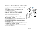
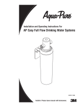
FILTER GUIDE AND REPLACEMENT
Filter replacement instructions:
n Replace with an InSinkErator
®
filter.
n Place pan or dish towel under the filter to
catch water drainage during change.
n Slowly turn the cartridge anticlockwise
completely until it stops (1/4 turn).
n Pull cartridge straight down and discard.
n Insert new cartridge into filter head.
n Top surface of cartridge will become flush
with the bottom of the filter head when
fully engaged.
n Turn the cartridge clockwise until it stops
(1/4 turn).
n Open tap to expel trapped air.
n Run water for 3 minutes before usage.
SEASONAL STORAGE/DRAINAGE
CARE AND USE
approx.
200°F (93°C)
ADJUSTING THE THERMOSTAT
Personal Injury:
Regularly check for signs of corrosion by
examining the appearance of the dispensed water
every three (3) months.
If there is any discoloration or rusty appearance,
unplug and drain unit as described in the Seasonal
Storage/Drainage section on this page of the
manual.
If the water discoloration remains after draining
and refilling unit, discontinue use and contact an
authorized InSinkErator service agent.
FILTRATION INFORMATION
Do not use with water that is microbiologically unsafe or of unknown quality without adequate
disinfection before or after the system.
To reduce the risk associated with property damage due to water leakage or flooding:
• Read and follow Use Instructions provided with the original system before installation
and use of this product.
To reduce the risk of water leakage or flooding, and to ensure optimal filter performance:
Change the disposable filter cartridge every six months or sooner if you
observe a noticeable reduction in water flow rate.
• Failure to replace the disposable filter cartridge at recommended intervals may
lead to reduced filter performance and cracks in the filter housing, causing
water leakage or flooding.
• For systems using two handle HC model faucets, operate only one handle
at a time.
• For questions or concerns, please contact Customer Service at
1-800-558-5700.
The InSinkErator Instant Hot Water Dispenser Filtration System offers two levels
of filtration, depending on the filter used: F-1000S is intended for use in filtering
particulates, chlorine taste and odor from drinking water, and has not been evaluated
for other uses; F-2000S reduces particulates, chlorine taste and odor, plus cysts,
lead, mercury, asbestos, benzene, atrazine, 2,4-D, Lindane, Carbofuran and
p-Dichlorobenzene. The system is typically installed (near or beneath a sink) where
filtered drinking water is desired, and must be installed, operated and maintained as
specified in the installation and use instructions.
16
WHAT TO DO
Water and steam spits
forcefully from spout
without turning on the
dispenser faucet.
Water is not hot.
Unit is boiling.
May be normal during initial setup.
• The unit is unplugged.
• The electric outlet is inoperative.
Activate faucet lever to release some water from
the tank.
Adjust water temperature using dial on tank front.
Remember that at higher altitudes, water boils
at lower temperatures.
Make sure the unit is connected to a properly grounded
electric outlet.
Make sure the circuit breaker or fuses are
functioning properly.
• Check that the outlet is not switched off.
Water is too hot
or not hot enough.
Thermostat is not adjusted to
your needs.
Adjust the thermostat slowly, then activate faucet lever for 20
seconds to bring in fresh water to be heated at the new setting.
Allow 5-7 minutes for water to reach new temperature.
Water comes out the
vent instead of spout.
• Outlet tube is blocked. Check that outlet tube is not kinked, twisted or pinched.
Unscrew spout end piece and clean out any debris.
Water is dripping from
the spout/vent
intermittently.
The expansion chamber isn’t draining
properly due to low water pressure.
• The spout is blocked.
Unplug the unit. If the dripping doesn’t stop after a few
minutes, check the supply valve to ensure that is fully
open and there are no obstructions in the water line
reducing the pressure below 30 psi (
i.e., a poorly mounted
saddle valve, a clogged water filter, or a partially opened
shut-off valve).
Unscrew spout end piece and clean out any debris.
Water is dripping
from the spout/vent
constantly.
Debris in the water line may be
in the faucet valve seat causing a
slow water leak.
Unscrew spout end piece and clean out any debris.
Activate faucet lever 7-10 times to flush faucet & lines.
Divided stream.
Debris in the end piece. Unscrew spout end piece and clean out any debris.
PROBLEM POSSIBLE CAUSE
FILTRATION ISSUES
If you are still experiencing trouble call the AnswerLine
®
1-800-558-5700.
Water taste or odor. Filter needs to be flushed out.
• Life of filter has expired.
Activate the faucet lever and run until the water is cold.
If there is no change, replace filter cartridge.
Please read Troubleshooting Guide and/or visit
www.insinkerator.com before calling AnswerLine
®
Water discoloration/rusty
appearance.
Corrosion of unit. Unplug and drain unit as described in the Seasonal
Storage/Drainage Section on page 15 of this manual. If the
water discoloration remains after draining and refilling unit,
discontinue use and contact an authorized InSinkErator
service agent.
New filter leaks or
doesn’t fit.
No water flow or
low water flow.
• Head and bracket not fully rotated.
• Filter O-ring breach.
• Life of filter has expired.
• Remove, inspect, reinstall filter cartridge.
Remove new filter, replace with old filter. Check operation.
If OK, reinstall new filter and recheck operation.
• Replace filter cartridge. See page 15.
TROUBLESHOOTING
17
NOTICE
F-1000 Cartridge (included with this system) Chemical & Mechanical Reduction Filter Specifications:
This cartridge provides mechanical and chemical reduction of chlorine taste & odor and particulate class III.
Filter Capacity:
500 gallons, depending on local water conditions. Note that while the testing was performed under
standa
rd laboratory conditions, actual performance may vary. Do not use with water that is microbiologically unsafe or
of unknown quality without adequate disinfection befo
re or after the system. For cold water use only.
Systems must be
installed and operated in accor
dance with the Manufacturer’s recommended procedures and guidelines. See warranty
ca
rd for warranty. For service and parts, contact your local dealer or InSinkErator
®
directly at 1-800-558-5700.
A
pplication guidelines/Water Supply Parameters for NSF Testing: Service flow of 0.75 gpm, community or
private well water suppl
y, water pressure of 20-120 psi (138-827 kPa), water temperature of 33˚F–100˚
Nominal
Particulate Class III,
5 µm to <15 µm
270,000 pts/mL
2.1 mg/L 2.0 mg/L ± 10%
At least 10,000
particles/mL
82 pts/mL 99.9%
85%
0.06 mg/L 97.0% 50% J-00082587
J-00119308
F Except as
noted, all testing performed at pH = 7.5
± 0.5, Flow: 0.75 gpm, Pressure: 60 psi, Temp: 20˚± 3˚C.
Contact an authorized InSinkErator service agent for repairs or replacement components. Replacement filters
F-1000 and F-2000 can be ordered by calling 800-558-5700, visiting shop.insinkerator.com, or by contacting
an authorized InSinkErator reseller.
Refer to the Performance Data Sheet for InSinkErator Filter System Model F-2000S
Replacement Cartridge: F-2000
Pressure: 30-120 (207-827 kPa) psi
Temperature: 33
º
F - 100
º
F
Flow Rate: 0.75 gpm
Capacity: 500 gallons
Tested & Certified by NSF International against NSF/ANSI Standard 42 in the following
InSinkErator Systems Only: GN1100, HC1100, GN2200, HC2200, GN2215, HC2215,
H3300 or HC3300 for the reduction of claims specified on the Performance Data Sheet.
For systems using two handle HC model faucets, operate only one handle at a time.
  • Page 1 1
  • Page 2 2
  • Page 3 3
  • Page 4 4
  • Page 5 5
  • Page 6 6
  • Page 7 7
  • Page 8 8
  • Page 9 9
  • Page 10 10
  • Page 11 11
  • Page 12 12
  • Page 13 13
  • Page 14 14
  • Page 15 15
  • Page 16 16
  • Page 17 17
  • Page 18 18
  • Page 19 19
  • Page 20 20
  • Page 21 21
  • Page 22 22
  • Page 23 23
  • Page 24 24
  • Page 25 25
  • Page 26 26

InSinkErator F-HC3300SN User guide

Type
User guide

Ask a question and I''ll find the answer in the document

Finding information in a document is now easier with AI