Symmetricom 8040C User manual
- Category
- Video switches
- Type
- User manual
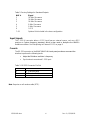
This manual is also suitable for

Rev. C, Jul 12, 2011
8040C/8040CLN Rubidium Frequency Standard
User Guide
Part Number: 15254-201

15254-201.docx
ii
Rev. C, 07/12/2011
Revision History
Revision
Date
Change
C.
12 July 2011
Added low phase noise option 8040CLN.

15254-201.docx
iii
Rev. C, 07/12/2011
Table of Contents
About this User Guide ............................................................................................................................... 1
Purpose ................................................................................................................................... 1
Conventions ............................................................................................................................ 1
Special Notices ...................................................................................................................................... 2
Limited Product Warranty ................................................................................................................ 3
Introduction ............................................................................................................................................. 4
Overview .................................................................................................................................. 4
Purpose of Equipment ........................................................................................................................... 4
Factory Configurations .................................................................................................................... 4
Installation ............................................................................................................................................... 5
Mounting ........................................................................................................................................ 5
Power Connection/Fuse/Voltage .................................................................................................... 5
Signal Connections ................................................................................................................................ 5
Output Signals .................................................................................................................................. 5
Input Signals .................................................................................................................................................. 6
Console ................................................................................................................................ 6
Operation ................................................................................................................................................. 7
Powering Up .................................................................................................................................. 7
Indicator LEDs ................................................................................................................................................... 7
Adjusting Oscillator Frequency ..................................................................................................... 8
Disciplining to External 1 PPS ......................................................................................................... 8
1 PPS Disciplining ............................................................................................................................ 8
Operation ................................................................................................................................... 9
Manual Control .................................................................................................................................. 9
Automatic Control .............................................................................................................................. 9
Configuring Outputs ............................................................................................................................... 9
Console .................................................................................................................................. 12
Host Terminal Emulator Setup ................................................................................................ 12
Specifications ................................................................................................................................. 13
Outputs .................................................................................................................................. 13
Sine Wave .......................................................................................................................... 13
Square Wave ............................................................................................................................................. 13

15254-201.docx
iv
Rev. C, 07/12/2011
Timing Outputs ......................................................................................................................................... 13
Timing Inputs ............................................................................................................................................. 13
Stability ..................................................................................................................................... 14
GPS Disciplining ...................................................................................................................................... 14
Aging ......................................................................................................................................... 14
Warm-up Time ............................................................................................................................................. 14
SSB Phase Noise .................................................................................................................................... 14
Environmental & Physical ................................................................................................................ 14
General ................................................................................................................................ 14
Remote System Interface and Control ..................................................................................... 15
AC Power Requirements ............................................................................................................. 15
Fuses ........................................................................................................................................ 15
Dimensions .......................................................................................................................... 15
Options .....................................................................................................................................................
16
Introduction ....................................................................................................................................................... 16
Twelve Output Option ............................................................................................................................ 16
Low Phase Noise Option ....................................................................................................................... 16
Technical Support ............................................................................................................................ 17
Maintenance ................................................................................................................................. 17
Customer Assistance ............................................................................................................................ 17
Preparation for Shipment ................................................................................................................ 17
Index .................................................................................................................................... 18

15254-201.docx
1
Rev. C, 07/12/2011
About this User Guide
Purpose
The 8040C/8040CLN User Guide describes the procedures for unpacking, installing,
using, maintaining the 8040C/8040CLN.
Conventions
This guide used the following conventions:
Acronyms and Abbreviations – Terms are spelled out the first time they appear in text.
Thereafter, only the acronym or abbreviation is used.
Revision Control – The title page lists the printing date and versions of the product this
guide describes.
Typographical Conventions- This guide uses the typographical conventions described
in the Table 1 below.
Table 1. Text Formats and Their Meanings
Text that appears this way...
... is
Product User Guide
A document title
SSU CRITICAL
An operating mode, alarm state, status, or
chassis label
Select File, Open...
A menu item to be selected by the user
Press Enter
A named keyboard key
Username:
Command line input or output
A
re-timing
application
Emphasis on a word or term
Symmetricom
does not
recommend
Special emphasis on a word or term

15254-201.docx
2
Rev. C, 07/12/2011
NOTE All notes have this symbol. Notes contain installation, operation, or maintenance
procedures, practices, conditions, or statements that alert you to important information
that may make your task easier or increase your understanding.
RECOMMENDATION All recommendations have this symbol.
Recommendations indicate manufacturer-tested methods or known functionality. They
contain installation, operation, or maintenance procedures, practices, conditions, or statements
that provide you with important information for optimum performance results.
CAUTION All Electrostatic Discharge (ESD) cautions have this symbol. They are
installation, operation, or maintenance procedures, practices, conditions, or statements
that if not strictly observed, may result in electrostatic discharge damage to, or
destruction of, static sensitive components of the equipment.
CAUTION All cautions have this symbol. Do not disregard cautions. They are
installation, operation, or maintenance procedures, practices, conditions, or statements
that if not strictly observed, may result in damage to or destruction of equipment or may
cause a long-term health hazard.
WARNING All warnings have this symbol. Do not disregard warnings. They are
installation, operation, or maintenance procedures, practices, or statements that if not
strictly observed, may result in personal injury or loss of life.
ELECTRICAL SHOCK HAZARD All electrical shock hazard warnings have this
symbol. To avoid serious personal injury or death, do not disregard electrical shock
hazard warnings. They are installation, operation, or maintenance procedures, practices, or
statements that if not strictly observed, may result in personal injury or loss of life.
Special Notices
Warnings, Cautions, Recommendations, and Notes attract attention to essential or
critical information in this guide. The types of information included in each are explained
in the following examples.

15254-201.docx
3
Rev. C, 07/12/2011
Limited Product Warranty
1. Hardware and embedded software - For a period of one (1) year from date of shipment by
Symmetricom, Symmetricom warrants that all Products shall be free from defects in design,
material, and workmanship; shall conform to and perform in accordance with Symmetricom's
published specifications, if any; shall be free and clear of any liens and encumbrances; and shall
have good and valid title. This warranty will survive inspection, acceptance, and payment by
Buyer. Symmetricom does not warrant that the operation of such Products will be uninterrupted or
error free. This warranty does not cover failures caused by acts of God, electrical or
environmental conditions; abuse, negligence, accident, loss or damage in transit; or improper site
preparation.
This warranty shall be null and void in the event (i) Buyer or any third party attempts repair of the
goods without Symmetricom's advance written authorization, or (ii) defects are the result of
improper or inadequate maintenance by Buyer or third party; (iii) of damage to said goods by
Buyer or third party-supplied software, interfacing or supplies; (iv) of improper use (including
termination of non-certified third party equipment on Symmetricom's proprietary interfaces and
operation outside of the product's specifications) by Buyer or third party; or (v) the goods are
shipped to any country other than that originally specified in the Buyer's purchase order.
Goods not meeting the foregoing warranty will be repaired or replaced, at Symmetricom's option,
upon return to Symmetricom's factory freight prepaid; provided, however that Buyer has first
obtained a return materials authorization number ("RMA Number") from Symmetricom authorizing
such return. The RMA Number shall be placed on the exterior packaging of all returns.
Symmetricom will pay shipping costs to return repaired or replacement goods to Buyer.
Symmetricom reserves the right to disallow a warranty claim following an inspection of returned
product. When a warranty claim is questioned or disallowed, Symmetricom will contact Buyer by
telephone or in writing to resolve the problem.
2. Software - Symmetricom warrants that for a period of ninety (90) days from date of shipment
by Symmetricom the accompanying media will be free from defects in materials and workmanship
under normal use. The physical media warranty does not apply to defects arising from misuse,
theft, vandalism, fire, water, acts of God or other similar perils. Symmetricom will not be liable for
any damages caused by the Buyer's failure to fulfill its responsibilities as stated above.
3. THE FOREGOING WARRANTY IS IN LIEU OF ALL OTHER WARRANTIES, EXPRESSED
OR IMPLIED, INCLUDING, BUT NOT LIMITED TO, ANY IMPLIED WARRANTIES OF TITLE,
MERCHANTABILITY, OR FITNESS FOR A PARTICULAR PURPOSE HOWSOEVER ARISING.
4. Limitation of Liability - The remedies provided herein are the Buyer's sole and exclusive
remedies. In no event or circumstances will Symmetricom be liable to Buyer for indirect, special,
incidental or consequential damages, including without limitation, loss of revenues or profits,
business interruption costs, loss of data or software restoration, or damages relating to Buyer's
procurement of substitute products or services. Except for liability for personal injury or property
damage arising from Symmetricom's negligence or willful misconduct, in no event will
Symmetricom's total cumulative liability in connection with any order hereunder or Symmetricom's
Goods, from all causes of action of any kind, including tort, contract, negligence, strict liability and
breach of warranty, exceed the total amount paid by Buyer hereunder. SOME JURISDICTIONS
DO NOT ALLOW CERTAIN LIMITATIONS OR EXCLUSIONS OF LIABILITY, SO THE ABOVE
LIMITATIONS OR EXCLUSIONS MAY NOT APPLY TO ALL BUYERS.

15254-201.docx
4
Rev. C, 07/12/2011
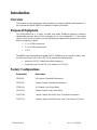
Introduction
Overview
This manual contains procedures and information for proper installation and operation of
the Symmetricom 8040C/8040CLN Rubidium Frequency Standard.
Purpose of Equipment
The 8040C/8040CLN is a highly accurate and stable Rubidium frequency reference
standard that provides atomic clock performance in a user-configurable 1 U rack-mount
chassis. Each of the connectors can be individually programmed to generate any of the
following frequency outputs:
1, 5 or 10 MHz sine wave
1, 5 or 10 MHz square wave
1 PPS
The 8040C uses Symmetricom’s model SA.22C Rubidium as its internal oscillator, and
provides direct user control via an RS-232 to perform the following tasks:
Adjust the SA.22C Rubidium oscillator frequency.
Syntonize (tune) the SA.22C to an external 1 PPS input.
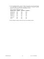
Factory Configurations
Part Number Description
15230-101 Six Outputs, Standard Performance.
15230-102 Twelve Outputs, Standard Performance.
15230-104 Six Outputs, Low Phase Noise
15230-105 Twelve Outputs, Low Phase Noise
15230-106 Twelve Outputs (all 10MHz sine), Standard Performance
15230-111 Twelve Outputs (all 10MHz sine), Low Phase Noise, DC power

15254-201.docx
5
Rev. C, 07/12/2011
Installation
Mounting
The Symmetricom 8040C mounts in standard 19-inch equipment racks, and takes up 1U
of vertical space (1.75”). The chassis depth is 12 inches. For best performance, the
operating environment should have a stable temperature. In addition, ensure that there
are no strong magnetic fields (>2 gauss) in the vicinity of the shelf since the unit’s
Rubidium oscillator is sensitive to DC and AC magnetic fields.
Power Connection/Fuse/Voltage
The Symmetricom 8040C is powered from an AC source or optionally from a 24VDC
source. (See Power Requirements, page 15). The AC fuse is located inside the AC
connector/filter on the rear panel. To change the fuse, open the cover on the rear
panel AC connector by applying a screwdriver to the connector’s cover slot. Once the
cover is open, the fuse holder may be removed for inspection or replacement.
The Symmetricom 8040C/8040CLN may be powered from 90 or 240 VAC. The
8040C automatically detects the input voltage therefore no manual configuration is
required.
ELECTRICAL SHOCK HAZARD - Use a locally approved power cord or power cord
adapter for connection to the power source.
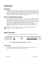
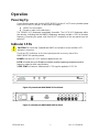
Signal Connections
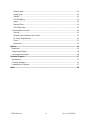
Output signal cables may be connected in any order to the rear panel BNC connectors.
Figure 1: 8040C/8040CLN Standard Configuration – Rear Panel
Output Signals
The standard Symmetricom 8040C/8040CLN has six BNC output connectors. The
outputs are factory-programmed as described in Table 2.

15254-201.docx
6
Rev. C, 07/12/2011
Table 2: Factory Settings for Standard Outputs
BNC # Signal
1 10 MHz Sine wave
2 10 MHz Sine wave
3 10 MHz Sine wave
4 5 MHz Sine wave
5 1 MHz Sine wave
6 1 PPS
7 –12 Optional. Not included in the base configuration
Input Signals
The 1 PPS IN connector takes a 1 PPS input from an external source, such as a GPS
receiver or Cesium frequency standard, which is then used to discipline the 8040C’s
Rubidium oscillator. See
Disciplining to External 1 PPS
on page 8.
Console
The RS-232 connector on the 8040C/8040CLN’s back panel provides a command line
interface to perform the following tasks:
Adjust the Rubidium oscillator’s frequency
Synchronize to an external 1 PPS input
Table 3. RS-232 Connector Pin-Out
DB9-F
Function
3
TX (Transmit Data)
2
RX (Receive Data)
5
GND (Signal Ground)
Note: Requires a null modem cable (DTE).

15254-201.docx
7
Rev. C, 07/12/2011
Operation
Powering Up
Connecting the power cord from the 8040C/8040CLN to the AC or DC source provides power
to the unit. For the DC version, on the power cord apply:
+24VDC on the red wire.
Ground or return on the black wire.
The POWER LED illuminates immediately thereafter. The LOCK LED illuminates within
five minutes, indicating that the 8040C’s frequency accuracy is within +/-5E-8 of absolute
frequency. Removing the power cord from the IEC receptacle on the rear panel turns the
power off.
Indicator LEDs
CAUTION
: Do not use the Symmetricom 8040C as a reference source until the LOCK
indicator is turned on.
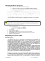
The three LED indicators on the front panel provide a cursory view of the
8040C/8040CLN operating status.
POWER
is lit when AC or DC power is applied to the unit.
LOCK
is lit when the unit’s Rubidium oscillator reaches operating temperature and its
frequency output is within specifications.
1 PPS SYNC
is lit when a valid external 1 PPS signal is applied to 1 PPS IN.
Figure 2: Symmetricom 8040C/8040CLN Front Panel
Figure 3: Symmetricom 8040C/8040CLN Rear Panel

15254-201.docx
8
Rev. C, 07/12/2011
NOTE
: A typical external counter does not have a resolution or accuracy high enough to
set this device, so do not reset the frequency unless established metrology methods are
used for frequency measurement resolution of <1 E-1 1.
Adjusting Oscillator Frequency
There are two reasons to adjust the unit’s frequency output:
To adjust for the effects of aging on the Rubidium oscillator’s frequency
To syntonize (or tune) the Rubidium oscillator’s frequency to that of a more
accurate primary frequency source.
The Symmetricom 8040C/8040CLN is a secondary frequency standard (i.e., much more
accurate than a quartz frequency standard, but not as accurate as a Cesium primary
frequency standard). By comparing the Symmetricom 8040C/8040CLN to an external
Cesium standard or GPS receiver, it can be readjusted periodically to match the primary
standard’s greater accuracy.
The 8040C/8040CLN output frequency is adjusted by using the RS-232 interface.
The “f” command allows the user to adjust the output frequency in parts <1E-11.
Example:
1. At the r > prompt, enter f
a. For a 5E-11 change, enter “f5<CR>”
b. For a -5E-11 change, enter “f-5<CR>”
2. Press ENTER
3. At the r > prompt, enter “t”
4. Under the “t”, enter 5987717 (this is the pass code save command)
5. Press ENTER (unless changes are saved they will not be recorded)
6. Response “Tuning Data Save”
Disciplining to External 1 PPS
1 PPS Disciplining
The advent of low cost GPS technology has brought about its widespread use
throughout the telecommunications industry. The GPS system provides 1 PPS with
extremely good long-term stability (e.g., <1E-12 averaged over 24 hours). However the
short-term stability of this signal is not suitable due to inherent noise perturbations in
GPS related to background noise, atmospheric conditions, cross talk, multipath, and
instabilities in the oscillators of GPS satellites and GPS receivers.
In order to provide the required stability for telecommunications, system designers must
combine the benefits of short-term stability (such as from a Rubidium or low noise
OCXO) with long-term stability (such as from GPS, Loran-C, GLONASS, or Cesium). In
the past, external disciplining circuitry was required to combine short-term and long-term
stability. The traditional approach involved adding an external circuit to the oscillator that
had a phase lock loop detector to handle disciplining algorithms.
Symmetricom is a leader in time and frequency design and has pioneered the use of
Rubidium oscillators in telecommunications. The model SA.22C Rubidium oscillator in the
Symmetricom 8040C/8040CLN provides an important new feature – built-in disciplining to
a 1 PPS input from an external reference. This new feature eliminates the need for
additional external disciplining circuitry. The 8040C/8040CLN is inherently capable of

15254-201.docx
9
Rev. C, 07/12/2011
disciplining to an external primary reference to remove frequency offsets due to long-term
aging.
Operation
Connect the 1 PPS source to the 1 PPS IN on the rear panel of the 8040C/8040CLN. The
8040C/8040CLN’s Symmetricom Synchronization Adaptive Algorithm (SSAA) qualifies
the 1 PPS input reference by detecting 256 valid 1 PPS input pulses and determining
the number of outliers based on the time constant. An outlier is detected when the
absolute time difference between the input 1 PPS and its expected time is greater than 1
microsecond. Once the SSAA detects two outliers (two bad 1 PPS pulses) or no input 1
PPS, the algorithm places the 8040C/8040CLN into flywheel (holdover) mode. The
flywheel mode provides for Rubidium short-term and long-term stability without the
benefit of an external reference. The 8040C/8040CLN remains in flywheel mode until 256
“good” 1 PPS input pulses are detected. Once the number of outliers is less than 2, the unit
disciplines to the external reference. This implementation was designed to support
applications where the reference input is a GPS receiver without serial
communications between the receiver and the 8040C/8040CLN. There are two modes
of operation for the 1 PPS input: manual and automatic.
Manual Control
The manual mode is beneficial to applications where the quality of 1 PPS is worse than
50 nanoseconds, or applications where the noise profile is well known and a
deterministic solution yielding more control to the system designer is desired. The
manual mode requires the user to input two parameters, which are tau (or time constant)
and dampening factor. Tau is expressed in seconds and determines the PLL time
constant for following a step in phase for the reference. The range of tau is 5 to 100,000
seconds. Tau values outside of this range put the unit in automatic disciplining mode.
The dampening factor determines the relative response time and ringing in response to
each step. There are no limitations for the dampening factor value; however, values
between 0.5 and 2 are strongly recommended.
Automatic Control
The automatic mode requires no user inputs to the SA.22C Rubidium oscillator.
Automatic mode is adaptive and changes the SSAA time constant as changes in the
1 PPS reference are detected. The automatic mode is optimized for a 1 PPS input with up to
50 nanoseconds RMS of noise such as from a GPS timing receiver. Since short-term
jitter of 50 nanoseconds is typically present on 1 PPS from a GPS reference, the
automatic mode is generally suitable for most applications.
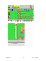
Configuring Outputs
The 8040C/8040CLN has the unique capability of providing flexible output
configurations. To change the output configuration of your 8040C/8040CLN:
1. Unplug the 8040C/8040CLN from the AC or DC power source and remove the
top cover by removing the Phillips head screws around the perimeter of the unit.
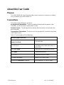
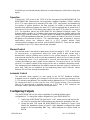
2. Locate the main PCB inside the 8040C/8040CLN as indicated in Figure 4 and
identify the dipswitches shown in Figure 5.
Each dipswitch configures the output
format on its corresponding BNC
(e.g., SW
1
configures the output format on
BNC
1
).

15254-201.docx
10
Rev. C, 07/12/2011
Figures 4 & 5: Dipswitch Locations for Configuring Outputs

15254-201.docx
11
Rev. C, 07/12/2011
3. Use the dipswitch positions shown in Table 4 to generate a specific output format
on a specific BNC. For example, to generate 10 MHz TTL on BNC3, set SW3
position 1 to ON, position 2 to OFF, and position 3 to OFF.
Table 4: Output Configuration Table
Output Format
Position 1
Position 2
Position 3
10 MHz Sine
OFF
OFF
OFF
10 MHz TTL
ON
OFF
OFF
5 MHz Sine
OFF
OFF
ON
5 MHz TTL
ON
OFF
ON
1 MHz Sine
OFF
ON
OFF
1 MHz TTL
ON
ON
Off
1 PPS
ON
ON
ON
4. After setting the outputs, replace the top cover and apply power.

15254-201.docx
12
Rev. C, 07/12/2011
Console
The Symmetricom Serial Interface Protocol (SSIP) provides user
communication with the 8040C/8040CLN through the serial port when the unit
is connected to a host PC or terminal. All “developer-mode” commands are
single-letter format.
Host Terminal Emulator Setup
Set up the comm port of the PC with the following configuration:
Data rate (Baud/BPS - see note below)
No parity
8 data bits
1 stop bit
No local echo (unit echoes)
No hardware or software flow control
All SSIP commands are a single ASCII letter. The baud rate of the
8040C/8040CLN is 57.6K.
Note: Requires a null modem cable (DTE).

15254-201.docx
13
Rev. C, 07/12/2011
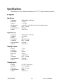
Specifications
All performance is at an ambient temperature of 25°C (77° F) unless otherwise specified.
Outputs
Sine Wave
Frequency 1MHz, 5MHz, & 10 MHz
Amplitude 1V RMS
Harmonic < –40 dBc
Non Harmonic < –60 dBc (< –80 dBc with Low Phase Noise option)
Connector BNC - Female
Load Impedance 50
Ohms
Location Rear Panel
Square Wave
Frequency 1MHz, 5MHz, & 10 MHz
Amplitude >3V Peak
Format TTL
Pulse Width 50% Duty Cycle
Connector BNC - Female
Load Impedance 50 Ohms
Location Rear Panel
Timing Outputs
Format 1 PPS
Amplitude >3V
Pulse Width 400 nS
Rise Time <20 nS
Jitter < 10ps RMS
Connector BNC - Female
Load Impedance 50 Ohms
Location Rear Panel
Timing Inputs
Quantity (1) 1 PPS Sync Input
Amplitude TTL Compatible
Connector BNC - Female
Load Impedance High Z
Location Rear Panel

15254-201.docx
14
Rev. C, 07/12/2011
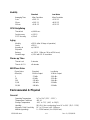
Stability
Standard Low Noise
Averaging Time Allan Deviation Allan Deviation
1 sec. <3.0E-11 <1.5E-11
10 sec. <1.0E-11 <8.0E-12
100 sec. <3.0E-12 <2.5E-12
GPS Disciplining
Time to lock </=1000 sec.
Freq Accuracy +/-1E-12
1 PPS Accuracy +/-30 nS
Aging
Monthly <5E-11 (after 30 days of operation)
Yearly <5E-10
Accuracy at <+/-5.0E-11
Shipment
Retrace <+/- 5E-11 ( 24hrs on, 24 hrs off, 24 hrs on)
Control Range +/-1E-6 with 1E-12 resolution
Warm-up Time
Time to Lock 5 minutes
Time to <1 E-9 <8 minutes
SSB Phase Noise
Phase Noise Standard Low Noise
Offset (Hz) 10 MHz Output 10 MHz Output
1 -72 dBc -100 dBc
10 -95 dBc -130 dBc
100 -130 dBc -144 dBc
1,000 -140 dBc -150dBc
10,000 -148 dBc -150dBc
Environmental & Physical
General
Operating Temperature 0C to 50 C (32 F - 122 F)
Temperature Coefficient <3E-10
Storage Temperature -40C to 71 C (-40F to 160 F)
Humidity 95% RH, Non-condensing from 0C to 50C (32 F - 122F)
Magnetic Field Sensitivity DC (+/-2 Gauss) <4E-11/Gauss
Altitude (operating) 0 – 15240 meters (0 to 50,000 feet)

15254-201.docx
15
Rev. C, 07/12/2011
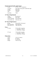
Remote System Interface and Control
Protocol RS-232-C (DTE Configuration)
Connector 9-pin female rectangular D subminiature type
Location Rear panel
Protocol 8 Data Bits
Stop 1 Stop bit
Baud Rate 57600
AC Power Requirements
Voltage 90 to 240 VAC
Frequency 47 to 63 Hz
Power (Operating) 25W (Operating)
Power (Warm Up) 45W (Warm Up)
DC Power Requirements
Voltage 18 to 36 VDC (24 Nominal)
Power (Operating) 25W (Operating)
Power (Warm Up) 45W (Warm Up)
Fuses
AC Input TO 2.0A, 250 V, slow blow
BUSSMAN GDC-2A
LITTELFUSE 218002
DC Input
TO 5.0A, 250 V, fast blow
BUSSMAN GDB-5A
LITTELFUSE 217005
Dimensions
Height 1.75" (1 UI) (44mm)
Width 19" (48 cm)
Depth 12" (30.5 cm)
Weight <6 lbs (<2.7 kg)

15254-201.docx
16
Rev. C, 07/12/2011
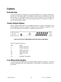
Options
Introduction
There are two optional configurations for the 8040C/8040CLN, the Twelve Output option
and the Low Phase Noise option. The additional outputs require an additional circuit card
that provides six configurable outputs that are set up the same as in the standard unit.
The Low Phase Noise option can be purchased with either the standard six outputs or
with the optional twelve outputs.
Twelve Output Option
With the Twelve Output option, the six additional outputs on channels 7 through 12 come
pre-configured the same as channels 1 through 6 in the standard configuration. They
can be reprogrammed as described in Configuring Outputs (page 9).
Figure 6: Back Panel of 8040C/8040CLN with the Twelve Output Option
Table 10: Output Connections
BNC Signal
7 10 MHz Sine wave
8 10 MHz Sine wave
9 10 MHz Sine wave
10 5 MHz Sine wave
11 1 MHz Sine wave
12 1 PPS
1-6 Standard Configuration
Low Phase Noise Option
The Low Phase Noise option does not require different operator instructions. This option
provides improved phase noise specifications as described in specifications section of
this manual.
Page is loading ...
Page is loading ...
-
 1
1
-
 2
2
-
 3
3
-
 4
4
-
 5
5
-
 6
6
-
 7
7
-
 8
8
-
 9
9
-
 10
10
-
 11
11
-
 12
12
-
 13
13
-
 14
14
-
 15
15
-
 16
16
-
 17
17
-
 18
18
-
 19
19
-
 20
20
-
 21
21
-
 22
22


Symmetricom 8040C User manual
- Category
- Video switches
- Type
- User manual
- This manual is also suitable for
Ask a question and I''ll find the answer in the document
Finding information in a document is now easier with AI
Related papers
-
Symmetricom 5087B Datasheet
-
-
-
-
-
-
-
-
-
Other documents
-
Microsemi SA.22c User manual
-
SRS PERF10 Owner's manual
-
Esoteric G-01X Owner's manual
-
 Pendulum GPS-88/89 User manual
-
APTECH GAUSS 8 User guide
-
 Pendulum GPS-12R/HS User manual
-
Millenium NT-X Quick start guide
-
Avaya H.323 User manual
-
Antelope Isochrone OCX-V Owner's manual
-

