Page is loading ...

097-58536-01
Issue 1: Apr 00
Copyright
2000 Symmetricom, Inc. All rights reserved. Printed in U.S.A.
58536A
GPS Distribution Amplifier
Information Note

Page 2 of 7
This information note describes accessory
equipment for a Symmetricom GPS
receiver system for a telecommunications
network.
The accessory is a distribution amplifier
for GPS antennas. Model 58536 is
designed to distribute the signal from the
GPS antenna to as many as four GPS
receivers.
For assistance, contact:
Symmetricom, Inc.
2300 Orchard Parkway
San Jose, CA 95131-1017
U.S.A. Call Center:
888-367-7966 (from inside U.S.A. only
– toll free)
408-428-7907
U.K. Call Center:
+44.7000.111666 (Technical
Assistance)
+44.7000.111888 (Sales)
Fax: 408-428-7998
E-mail: [email protected]m
Internet: http://www.symmetricom.com
Warning Symbols Used In This Note
!
Instruction manual symbol; the product will be
marked with this symbol when it is necessary for the
user to refer to the instruction manual.
Indicates hazardous voltages.
Indicates earth (ground) terminal.
or
Indicates terminal is connected to chassis when such
connection is not apparent.
Indicates Alternating current.
Indicates Direct current.

3 of 7
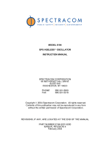
PORT 1
DC POWER
DC POWER
PORT 4
ANTENNA
INPUT
PORT 2
DC POWER
DC POWER
PORT 3
GPS DISTRIBUTION AMPLIFIER
58536A
Figure 1. 58536A GPS Distribution Amplifier
1.0 Introduction
The 58536A GPS distribution amplifier is one component of a complete line of GPS
accessories available from Symmetricom. These accessories are designed to deliver precise
GPS signals over a wide temperature range and in harsh environmental conditions.
The distribution amplifier is required if you wish to distribute the signal from a single
antenna to as many as four GPS receivers.
2.0 Description
The 58536A consists of a broadband, unity gain amplifier and a 1:4 signal splitter. Designed
for use with GPS antennas, the unit features a high degree of isolation to eliminate feedback
and interaction between any GPS systems connected to it.
Power to the unit is supplied by a GPS timing receiver connected to one of the four ports.
This means that the distribution amplifier will operate as long as there is at least one
working GPS receiver connected to any one of the distribution amplifier ports.
3.0 Use with Non-Symmetricom Systems
Although designed for use with Symmetricom GPS receivers, the
58536A can be used with
other GPS receiver and antenna systems.
The 58536A operates over a voltage range of +4.5 Vdc to +13 Vdc. Power from the GPS
receiver is passed through to the antenna.

Page 4 of 7
Note:
When installing any electrical device always follow the rules prescribed by your
local electrical and building ordinances. Contact Symmetricom as described below for
additional technical recommendations for installation.
4.0 Considerations for Long Cable Runs
Due to process variations in the fabrication of the 58536A, the gain through the device can
vary
±
3 dB. Assume the worst case loss of the 58536A (
−
3 dB) when determining if line
amplifiers are necessary in your GPS antenna system. If an amplifier is required, consider
the
58529A line amplifier with L1 bandpass filter.
Note:
In general, an amplifier is required if there is more than 20 dB of cable loss
between the GPS antenna and the GPS receiver. Two amplifiers are recommended
when there is more than 40 dB of cable loss.
Calculate cable loss:
The assumed worst case loss through the 58536A (
−
3 dB) is equal to:
•
18 meters (60 ft) of cable length when using LMR 400 cable
•
8 meters (25 ft) of cable length when using RG-213 cable
Use this procedure to determine if line amplifiers are required:
1. First, calculate the distance from the antenna to the most distant receiver.
2. Determine the signal loss due to the type and length of cable used.
3. Add the assumed worst case loss through the 58536A in terms of cable length.
4. Compare the result to the requirements for line amplifiers below. If line amplifiers are
required, they should be added as close to the GPS antenna as possible (within 10
meters/33 feet).
5.0 Requirements for Line Amplifiers
This section provides information that will help you determine if line amplifiers are required
for your GPS antenna system installation.
For LMR 400 cable:
If the estimated cable length (include the cable length equivalent to the assumed worst case
loss through the 58536A) between the antenna and the most distant GPS receiver is:
•
Less than 115 meters (377 feet), no line amplifier is necessary.
•
More than 115 meters (377 feet) and less than 240 meters (787 feet), you need 1 line
amplifier.
•
More than 240 meters (787 feet) and less than 360 meters (1181 feet), you need 2 line
amplifiers.
•
More than 360 meters (1181 feet), contact Symmetricom for assistance.

5 of 7
For RG-213 cable:
If the estimated cable length (include the cable length equivalent to the assumed worst case
loss through the 58536A) between the antenna and the most distant GPS receiver is:
• Less than 53 meters (174 feet), no line amplifier is necessary.
• More than 53 meters (174 feet) and less than 105 meters (345 feet), you need 1 line
amplifier.
• More than 105 meters (345 feet) and less than 158 meters (518 feet), you need 2 line
amplifiers.
• More than 158 meters (518 feet), contact Symmetricom for assistance.
For Non-Symmetricom cable:
If using other cable, the need for amplifiers can be estimated using the following guidelines:
•
If your installation involves less than 20 dB of cable loss, an amplifier is not required.
•
If there is from 20 to 39 dB of cable loss, one amplifier will provide sufficient gain to
ensure proper operation.
•
If there is from 40 to 59 dB of cable loss, two amplifiers are recommended for proper
operation. This is the maximum cable loss for which the GPS receiver can provide
power. If you have calculated more than 60 dB of cable loss for your installation, then a
lower-loss cable must be used. Symmetricom’s lowest-loss standard cable is LMR 400
(58520A or 58521A) with a loss of 5 dB per 30.5 meters (100 ft). Contact Symmetricom if
you need information on the availability of lower-loss cable.
Note:
These guidelines include a safety margin to account for any degrading of signal
strength due to temperature changes in the cable, variation of sensitivity in the
antenna and receiver, and minor errors made in estimating cable loss.
6.0 Installation
The 58536A distribution amplifier can be mounted in any indoor or outdoor location. It
should be positioned after the antenna, any line amplifiers, and any lightning arrestors, as
the last item before the GPS receivers.
Note:
Protecting outdoor connections is recommended. Refer to Environmental
Considerations for more information.
Environmental Considerations for Outdoor Installations
It is recommended that all cable connections that are outdoors or exposed to wet or humid
environments be sealed to prevent moisture from entering the connector. For maximum
protection, a multi-barrier process is suggested.
A Multi-Barrier Process
A multi-barrier process provides maximum protection for connections. An example of this
process might consist of the following steps:
1. Wrap the connection with a self-fusing, insulating tape (for example, 3M Scotch™ 23
Rubber Splicing Tape).
2. Overwrap the self-fusing tape with a layer of vinyl electrical tape (for example, 3M
Scotch™ Super 88 Vinyl Electrical Tape).

Page 6 of 7
3. Cover with a layer of oil and water resistant coating (for example, 3M Scotchkote™
Electrical Coating.
Note:
For specifics, please refer to the manufacturer’s instructions.
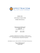
Dimensions of Distribution Amplifier
Figure 2 shows the major dimensions of the distribution amplifier.
115.0 mm
56.0 mm
2 x 4.4 mm Dia
mounting holes
105.0 mm
130.4 mm
50.0 mm
33.5 mm
64.0 mm
34.5 mm
14.5 mm
PORT 1
DC POWER
DC POWER
PORT 4
ANTENNA
INPUT
PORT 2
DC POWER
DC POWER
PORT 3
GPS DISTRIBUTION AMPLIFIER
58536A
94.8 mm
Figure 2. 58536A GPS Distribution Amplifier
7.0 Maintenance
No periodic maintenance is required for the distribution amplifier. However, it is
recommended that all components of the antenna system be checked periodically and
replaced, if necessary, as specified in your company procedures.

7 of 7
8.0 Specifications/Characteristics
The following table presents the specifications for the 58536A GPS Distribution Amplifier.
Table 1. 58536A Specifications/Characteristics
Frequency Bandwidth (3 dB)
1575.42 MHz
±
10 MHz
Gain (antenna to output)
0 dB
±
3 dB (typical) @ 1575.42 MHz (L1)
Noise Figure 5 dB (typical) @ 25°C
VSWR Input: 1.2:1 (typical) @ L1
Output: 1.6:1 (typical) @ L1
Isolation
−
26 dB (typical) @ 1575.42 MHz (L1)
−
50 dB (typical) @ f
≤
L1
−
40 MHz
−
50 dB (typical) @ f
≥
L1
+
40 MHz
DC Power
Operating voltage
*
(see Caution
below)
Damage level
Operating current
+
4.5 Vdc to
+
13 Vdc
>
18 Vdc, either polarity
23 mA to 48 mA (depending on operating voltage)
AC Input Level (antenna signal)
Impedance
Maximum operating
Damage level
50
Ω
, nominal
−
25 dBm
+
17 dBm @ L1
AC (output ports)
Impedance
50
Ω
, nominal
Connectors 5 Type-N Jacks
Operating Environment
−
35°C to
+
75°C
Weight 0.5 kg
Dimensions (including connectors) 95 mm W x 130 mm L x 35 mm H
Mounting Holes 2 holes, 4.4 mm diameter
Caution:
*Operating voltage is passed through to the antenna. The 58532A antenna
operates on
+
5 Vdc nominal. Applying greater than
+
5 Vdc nominal may damage the
58532A.
/