Page is loading ...

11 GHz FDD
Licensed Backhaul Radio
Model: AF‑11FX

Introduction
Thank you for purchasing the Ubiquiti Networks® airFiber®
AF-11FX. This Quick Start Guide is designed to guide you
through installation. Warranty terms, safety notices, and
compliance information are in the airFiberAF-11FX User
Guide, available at: downloads.ubnt.com/airfiber
The AF-11FX is available in two configurations:
• Low-Band: AF-11-FX-L
Includes Low-Band Duplexer, model AF-11FX-DUP-L
• High-Band: AF-11-FX-H
Includes High-Band Duplexer, model AF-11FX-DUP-H
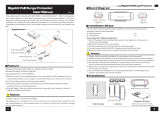
Package Contents
Low-Band Duplexer
or
airFiber AF-11FX High-Band Duplexer Cable Ties (Qty. 2)
11 GHz FDD
Licensed Backhaul Radio
Model: AF-11FX
airFiber Gigabit PoE
(50V, 1.2A)
Power Cord Quick Start Guide
TERMS OF USE: Ubiquiti radio devices must be professionally installed. Shielded Ethernet
cable and earth grounding must be used as conditions of product warranty. It is the
customer’s responsibility to follow local country regulations, including operation within legal
frequency channels, output power, and Dynamic Frequency Selection (DFS) requirements.

Antenna Compatibility
The airFiber AF-11FX radio is designed for use with the
airFiberX antenna model AF-11G35
*
.
Installation Requirements
• Clear line of sight between airFiber radios
• Vertical mounting orientation
• Mounting point:
• At least 1 m below the highest point on the structure
• For tower installations, at least 3 m below the top of
thetower
• Ground wires – min. 10 AWG (5 mm
2
) and max. length:
1m. Asa safety precaution, ground the airFiber radio to
grounded masts, poles, towers, or grounding bars.
WARNING: Failure to properly ground your
airFiber radio will void your warranty.
• (Recommended) 2 Outdoor Gigabit PoE surge protectors
Note: For guidelines about grounding and lightning
protection, follow your local electrical regulatory
codes.
• (Optional) For MIMO mode operation: A second Duplexer of
the same type as the one included with the AF-11FX radio:
• High-Band Duplexer (model AF-11FX-DUP-H) or
• Low-Band Duplexer (model AF-11FX-DUP-L)
• (Optional) If not using PoE: DC power source and 12/30 AWG
power cable.
• Outdoor, shielded Category 6 (or above) cabling and
shielded RJ-45 connectors are required for all wired Ethernet
connections.
* Check your local/regional regulations for the allowable antenna gain
allowed for your application.

Hardware Overview
Port Cover
LED
Panel
Duplexer
Shroud
Captive
Screw
Chain 0:
Connects to
Antenna
* Chain 1 (Under Cap)
Connects to Antenna
(Requires Optional
Second Duplexer)
Duplexer Cap*

Ports
Reset
Button
Management
Port
Data
Port
VDC IN
50V
1.2A
Management Port 10/100 Mbps, secured Ethernet port for
configuration. In-Band Management is enabled by default
in the airFiber Configuration Interface. When In-Band
Management is disabled, the MGMT port is the only port that
can monitor, configure, and/or update firmware.
Reset Button To reset to factory defaults, press and hold the
Reset button for more than 10 seconds while the device is
already poweredon.
Data Port Gigabit PoE port for handling all user traffic and
powering the device.
VDC IN The terminal block can be used to power the AF-11FX
with +50VDC 1.2A DC power instead of PoE.

Duplexer Ports
TX 0 RX 0 RX 1 TX 1
Top View of AF-11FX
(Duplexer Shroud
Removed)
RX 0
TX 0
TX 1
RX 1
TX 0, RX 0 The TX and RX SMA ports for the Chain 0 Low-Band
Duplexer or High-Band Duplexer (SISO and MIMO modes).
RX 1, TX 1 The RX and TX SMA ports for the Chain 1 Low-Band
Duplexer or High-Band Duplexer (MIMO mode only). In SISO
mode, these unused ports are protected by the Duplexer Cap.
Duplexer
SMA Ports
N Connector
Low-Band Duplexer High-Band Duplexer
Note:
The AF-11FX includes one Duplexer (Low-Band
Duplexer or High-Band Duplexer, depending on the
model) for SISO mode.
MIMO mode requires a second
Duplexer (not included) of the same band type.
N Connector Female N-type connector into which the
antenna cable is plugged.
SMA Port High-band and low-band channel SMA ports.

LEDs
Signal LEDs
Signal 4 LED will light blue when on.
Signal 3 LED will light green when on.
Signal 2 LED will light yellow when on.
Signal 1 LED will light red when on.
Bootup to airOS When powering on, the Power, MIMO, LINK,
and Signal 1-4 LEDs light on. Once the CPU code takes over, the
MIMO, LINK, and Signal 1-3 LEDs turn off. Signal 4 LED remains
lit to indicate the boot sequence is underway.
Initializing airFiber Software When the airFiber application
begins to boot under airOS, the Signal 4 LED goes from solidly
on to a 2.5 Hz flash. This continues until the AF-11FX is fully
booted.
Signal Level Once fully booted, the Signal 1-4 LEDs act as a
bar graph showing how close the AF-11FX is to ideal aiming.
This is auto-scaled based on the link range, the antenna gains,
and the configured TX power of the remote AF-11FX. Each
Signal LED has three possible states: On, Flashing, and Off. All
Signal LEDs would be solidly on in an ideal link. For example,
if the link has a 1 dB loss, the Signal4 LED will flash; a 2 dB loss
and the Signal4 LED will turn off. The full bar graph LED states
are shown below.
dB
loss
0 -1 -2 -3 -4 -5 -6 -7 -8 -9 -10 -11 -12 -13
1 F 0 0 0 0 0 0 0 0 0 0 0 0
1 1 1 F 0 0 0 0 0 0 0 0 0 0
1 1 1 1 1 F F 0 0 0 0 0 0 0
1 1 1 1 1 1 1 1 1 1 F F F 0
0 = Off, 1 = On, F = Flashing

Additional LEDs
LED State Status
LINK
Off RF Off
Short Flash* Syncing
Normal Flash* Beaconing
Long Flash* Registering
On Operational
MIMO
Off Radio Configured in SISO Mode
On Radio Configured in MIMO Mode
MGMT
Off No Ethernet Link
On Ethernet Link Established
Random Flashing Ethernet Activity
DATA
Off No Ethernet Link
On Ethernet Link Established
Random Flashing Ethernet Activity
Off No Power
On Powered On
* Short Flash (1:3 on/off cycle)
Normal Flash (1:1 on/off cycle)
Long Flash (3:1 on/off cycle)
*640-00256-03*
640-00256-03

Installation Overview
We recommend that you configure your paired AF-11FX radios
before site installation. The overview below summarizes the
installation procedure, and the subsequent sections provide
detailed installation information.
• Install the Duplexer(s) in the AF-11FX radio.
• Connect the airFiber Gigabit PoE adapter to the DATA port,
and connect your computer to the MGMTport.
• Configure the AF-11FX.
• Install a ground wire and mount the AF-11FX on the
airFiber AF-11G35 antenna (or a compatible antenna).
• At the installation site, install the antenna with the mounted
AF-11FX radio (see the antenna’s Quick Start Guide for
installation instructions).
• Connect the DATA port to your LAN, and connect power
(PoE or DC power) to the AF-11FX.
• Establish and optimize the RF link.
Installing the Duplexer for SISO Mode
1. Loosen the Captive Screw on top of the Duplexer Shroud
and remove the Duplexer Shroud.
Dust Covers
Duplexer
Shroud

2. Remove the Dust Covers from the TX0 and RX0 ports of the
AF-11FX radio. Do not remove the Dust Covers from the
RX1 and TX1 ports.
3. Seat the SMA Ports of the Duplexer onto the TX0 and RX0
ports of the AF-11FX, while positioning the Low Channel
and High Channel ports to yield the required transmit and
receive frequencies.
4. Secure the Duplexer to the radio by tightening the collars
on the SMA Ports.
WARNING: Tighten the collars alternately, turning
one collar a half turn, then the other collar a half turn,
and so on, until both are fully tightened. Failure to do
so may result in damage to the Duplexer.

5. Reseat the Duplexer Shroud onto the AF-11FX radio and
tighten the Captive Screw to secure the Duplexer Shroud.
6. Repeat steps 1-4 for the radio to be used on the other
end of the link, ensuring that the numbers on the second
radio’s Duplexer are in the reverse order of the numbers on
first radio’s Duplexer.
Note: For example, if the numbers on the first radio’s
Duplexer are (left to right) 1/3, then the numbers on
the second radio’s Duplexer should be 3/1.
Installing an Optional Duplexer (MIMO Mode)
Note: MIMO operation requires two licenses, one per
polarization and a second Duplexer of the same band.
1. Loosen the Captive Screw on top of the Duplexer Shroud
and remove the Duplexer Shroud.
Dust Covers
Duplexer
Shroud
2. Remove the Dust Covers from the radio’s four SMA ports.

3. Seat the SMA Ports of one Duplexer onto the TX0 and RX0
ports of the AF-11FX, while positioning the Low Channel
and High Channel ports to yield the required transmit and
receive frequencies.
4. Attach the second Duplexer (not included) to the RX1 and
TX1 ports, ensuring that the numbers on the adjacent sides
of the Duplexers match. (The numbers on the Duplexer on
the right should be in the reverse order of the numbers on
the Duplexer on the left.)

5. Secure each Duplexer to the radio by tightening the collars
on the SMA Ports.
WARNING: Tighten the collars alternately, turning
one collar a half turn, then the other collar a half turn,
and so on, until both are fully tightened. Failure to do
so may result in damage to the Duplexer.
6. Remove the Duplexer Cap and Cap Washer from the
AF-11FX by removing the Cap Screw located inside the
shroud.
Cap Screw
Cap Washer
Duplexer Cap
Duplexer Shroud
(side view)

7. Reseat the Duplexer Shroud onto the AF-11FX radio and
tighten the Captive Screw to secure the Duplexer Shroud.
8. Repeat steps 1-7 for the other radio to be used in the link,
ensuring that the numbers on the second radio’s Duplexers
are in the reverse order of the numbers on the first radio’s
Duplexers.
Note: For example, if the numbers on the first radio’s
Duplexers are (left to right) 2/4 and 4/2, the numbers on
the second radio’s Duplexers should be 4/2 and 2/4.
Connecting Power over Ethernet
1. Lift the release latch on the bottom of the AF-11FX and
slide the Port Cover off.

2. Connect an Ethernet cable to the DATA port.
3. Connect the Ethernet cable from the DATA port of the
AF-11FX to the POE port of the adapter.
WARNING: Use only the included adapter, model
GP-C500-120G. Failure to do so can damage the unit
and void the product warranty.
4. Connect the Power Cord to the adapter’s power port.
Connect the other end of the Power Cord to a poweroutlet.

airFiber Configuration
The instructions in this section explain how to access the
airFiber Configuration Interface and configure the following
settings:
• Wireless Mode Configure one AF-11FX as the Master and
the other as the Slave.
• Frequency Setting The TX Frequency and RX Frequency
settings must be the reverse of each other on both the
Master and the Slave.
1. Connect an Ethernet cable from your computer to the
MGMT port on the AF-11FX.
2. Configure the Ethernet adapter on your computer with a
static IP address on the 192.168.1.x subnet.
3. Launch your web browser. Type http://192.168.1.20 in the
address field and press enter (PC) or return (Mac).

4. The login screen will appear. Enter ubnt in the Username
and Password fields. Select your Country and Language.
You must agree to the Terms of Use to use the product.
Click Login.
5. Click Settings, and then click the Wireless tab.

6. Configure the Basic Wireless Settings:
a. For one AF-11FX, select Master as the Wireless Mode.
For the other AF-11FX, keep the default,Slave.
b. Enter a name in the Link Name field. This should be the
same on both the Master and the Slave.
c. If needed, change the Channel Bandwidth, Output Power
and/or Maximum Modulation Rate settings.
7. Configure the TX Frequency and RX Frequency.
Note: One airFiber radio’s TX Frequency is the other
radio’s RX Frequency, and vice versa.
8. Configure the Wireless Security:
a. Select the Key Type, HEX or ASCII.
b. For the Key field:
- HEX Enter 16 bytes (eight, 16-bit hexadecimal digits:
0-9, A-F, or a-f). You can omit zeroes and use colons,
similar to the IPv6 format.
Note: The airFiber Configuration Interface
supports IPv6 formats excluding dotted quad
and “::” (double-colon) notation.
- ASCII Enter a combination of alphanumeric
characters (0-9, A-Z, or a-z).
9. Click Save Changes.

10. In-Band Management is enabled by default, so each airFiber
radio must have a unique IP Address. (If the airFiber radios
use the same IP Address, you may lose access to the airFiber
radios via the DATA ports.) Click the Network tab.
a. For the Management IP Address option:
- DHCP Keep the default, DHCP, to use DHCP
reservation on your router to assign a unique
IPAddress.
- Static
Change the IP Address, Netmask, and other
settings to make them compatible with your network.
b. Click Save Changes.
11. Disconnect the Ethernet cables from the MGMT and DATA
ports on the AF-11FX. Configuration of the AF-11FX radio
is complete.
Repeat the instructions in the airFiber Configuration section on
the other AF-11FX radio.
For details on the airFiber Configuration Interface, refer to the
airFiber AF-11FX User Guide, available at:
downloads.ubnt.com/airfiber

Hardware Installation
Install a Ground Wire
1. Remove the nut from the Ground Bonding Point located on
the back of the AF-11FX, near the lower-right corner.
Ground
Bonding
Point
2. Attach a ground wire (min. 10 AWG or 5 mm
2
) to the lug
and replace the nut to secure the wire.
3. At the installation site, secure the other end of the ground
wire to a grounded mast, pole, tower, or grounding bar.
WARNING: Failure to properly ground your
airFiber radio will void your warranty.
Note: The ground wire should be as short as
possible and no longer than one meter in length.
/