Page is loading ...

5 GHz Full Duplex Point-to-Point
Gigabit Radio
Models: AF-5, AF-5U

i
Table of ContentsairFiber
®
AF5/AF5U User Guide
Ubiquiti Networks, Inc.
Table of Contents
Chapter 1: Overview ................................................1
Introduction. . . . . . . . . . . . . . . . . . . . . . . . . . . . . . . . . . . . . . . . . . . . . . . . . . . . . . . . . . . . . . . . . . . . . . 1
Package Contents ................................................................1
airFiber Configuration Interface SystemRequirements ............................1
Hardware Overview ..............................................................1
Chapter 2: Installation ..............................................3
Link Planning .....................................................................3
Installation Requirements ........................................................3
Installation Overview .............................................................4
Connecting Power over Ethernet ..................................................4
airFiber Configuration ............................................................5
Hardware Installation .............................................................7
Connecting Ethernet ............................................................10
Alignment. . . . . . . . . . . . . . . . . . . . . . . . . . . . . . . . . . . . . . . . . . . . . . . . . . . . . . . . . . . . . . . . . . . . . . .12
Chapter 3: Navigation .............................................18
Accessing the airFiber Configuration Interface ...................................18
Product Verification .............................................................19
Interface Tabs ...................................................................19
Chapter 4: Main Tab ...............................................20
Status ...........................................................................20
Monitor .........................................................................22
Chapter 5: Wireless Tab ............................................23
Basic Wireless Settings ...........................................................24
Frequency Settings ..............................................................25
Wireless Security ................................................................25
Chapter 6: Network Tab ...........................................26
Management Network Settings ..................................................26
Chapter 7: Advanced Tab ..........................................28
Wireless Settings ................................................................28
DATA Port Ethernet Settings .....................................................28
MGMT Port Ethernet Settings ....................................................30

ii
Table of ContentsairFiber
®
AF5/AF5U User Guide
Ubiquiti Networks, Inc.
Chapter 8: Services Tab ...........................................31
Ping Watchdog ..................................................................31
SNMP Agent. . . . . . . . . . . . . . . . . . . . . . . . . . . . . . . . . . . . . . . . . . . . . . . . . . . . . . . . . . . . . . . . . . . . .32
Telnet Server ....................................................................33
NTP Client .......................................................................33
Dynamic DNS ...................................................................33
System Log ......................................................................34
Device Discovery ................................................................34
Chapter 9: System Tab ............................................35
Firmware Update ................................................................35
Device ..........................................................................36
Date Settings ....................................................................36
System Accounts ................................................................36
Miscellaneous ...................................................................37
Location ........................................................................37
Device Maintenance .............................................................37
Configuration Management .....................................................37
Chapter 10: Tools ..................................................38
Align Antenna ...................................................................38
Discovery .......................................................................39
Ping .............................................................................39
Traceroute ......................................................................39
Appendix A: Specifications ........................................40
Appendix B: Safety Notices ........................................42
Electrical Safety Information .....................................................42
Appendix C: Warranty .............................................43
Limited Warranty ................................................................43
Appendix D: Compliance Information .............................45
Installer Compliance Responsibility ..............................................45
FCC .............................................................................45
Industry Canada .................................................................45
RF Exposure Warning ............................................................45
Australia and New Zealand ......................................................45
CE Marking ......................................................................45
Frequency Ranges and Power Levels per Country/Region ........................46
RoHS/WEEE Compliance Statement ..............................................48
Appendix E: Declaration of Conformity ............................49
Appendix F: Contact Information ..................................50
Ubiquiti Networks Support ......................................................50

1
Chapter 1: OverviewairFiber
®
AF5/AF5U User Guide
Ubiquiti Networks, Inc.
airFiber Configuration Interface
SystemRequirements
• Microsoft Windows Vista, Windows 7, Windows 8, Linux,
or Mac OS X
• Java Runtime Environment 1.6 (or above)
• Web Browser: Mozilla Firefox, Apple Safari, Google
Chrome, or Microsoft Internet Explorer 8 (or above)
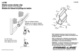
Hardware Overview
Side
Grounding Point
Elevation Rod
Hex Nut
to adjust
Elevation Rod
Pre-Installed
M10 x25
Flanged Bolts
Lanyard Attachment
Loop
Lanyard Attachment
Loop
Assembled View
Chapter 1: Overview
Introduction
Thank you for purchasing the Ubiquiti Networks®
airFiber® 5GHz Full Duplex Point-to-Point Gigabit Radio.
This User Guide is for use with the following models:
Model Description Operating Frequency*
AF-5 Supports mid-band frequencies 5470 - 5950 MHz
AF-5U Supports high-band frequencies 5725 - 6200 MHz
* Refer to “Specifications” on page 40 for more
information.
The mid-band model, AF-5, features the popular mid-band
frequencies, which are freely used in many parts of
theworld. The high-band model, AF-5U, which can
operate in the 5.7 - 6.2 GHz bands, has robust filtering to
enable co-location with devices operating in the lower 5
GHz bands while allowing operation at a higher output
power in many areas of the world.
The same instructions apply to both models, and the User
Guide will refer to both models as the airFiber AF-5.
Package Contents
airFiber
AF-5/AF-5U
I-Bracket Upper Mount Bracket
with Elevation Rod
Lower Mount
Bracket
Pole Clamps
(Qty. 2)
M10x150 Carriage Bolts
(Qty. 4)
M10x100 Carriage Bolts
(Qty. 2)
M8x14 Serrated Flange Bolts
(Qty. 4)
Azimuth Support Brackets
(Qty. 2)
M10 Serrated Flange Nuts
(Qty. 6)
Cable Ties
(Qty. 2)
GigE PoE Adapter
(50V, 1.2A)
Power Cord Quick Start Guide
TERMS OF USE: Ubiquiti radio devices must be professionally installed. Shielded Ethernet cable and
earth grounding must be used as conditions of product warranty. TOUGHCable
™
is designed for
outdoor installations. It is the customer’s responsibility to follow local country regulations, including
operation within legal frequency channels, output power, and Dynamic Frequency Selection (DFS)
requirements.

2
Chapter 1: OverviewairFiber
®
AF5/AF5U User Guide
Ubiquiti Networks, Inc.
Interfaces
GPS
MASTER
LINK
RESET
OVERLOAD
8X
6X
4X TO 0.25X
REMOTE
LOCAL
MANAGEMENT DATA
AUX
ACT SPEED ACT SPEED
Interface Description
Reset Button
To reset to factory defaults, press and hold the
Reset button for more than five seconds while
the unit is already powered on.
Remote Display
Displays the received signal strength in dBm of
the remote airFiber radio.
Local Display
Displays the received signal strength in dBm of
the local airFiber radio.
Management Port
10/100 Mbps, secured port for configuration.
By default, this is the only port that can
monitor, configure, and/or update firmware.
Aux Port Port for audio tone aiming.
Data Port 10/100/1000 Mbps port handles all user traffic.
LEDs
GPS
MASTER
LINK
RESET
OVERLOAD
8X
6X
4X to 0.25X
REMOTE
LOCAL
AUXMANAGEMENT DATA
ACT SPEED ACT SPEED
LED State Status
GPS
Off No GPS Synchronization
On Operational (Strong Signal)
Normal Flash* Non-Operational (Weak Signal)
Master
Off Slave mode
On Master mode
Link Status
Off RF Off
Short Flash*
Syncing
DFS countries only:
• DFS CAC
• RADAR Detected
Normal Flash* Beaconing
Long Flash* Registering
On Operational
Remote On
Displays the received signal
strength in dBm of the remote
airFiber radio.
Local On
Displays the received signal
strength in dBm of the local
airFiberradio.
Overload Fast Flash
Overload Condition (Identify and
eliminate any source of strong
in-band interference.)
(Unlabeled) On 10x (1024QAM MIMO)
8x On 256QAM MIMO
6x On 64QAM MIMO
4x to 0.25x
On 16QAM MIMO
Long Flash* QPSK MIMO
Normal Flash* 1x QPSK xRT
™
**
Short Flash* ¼x QPSK xRT**
* Short Flash (1:3 on/off cycle)
Normal Flash (1:1 on/off cycle)
Long Flash (3:1 on/off cycle)
** xtreme Range Technology
Port LEDs
LED State Status
Management
Act
Off No Ethernet Link
On Ethernet Link Established
Random Flashing Ethernet Activity
Speed
Off 10 Mbps
On 100 Mbps
Data
Act
Off No Ethernet Link
On Ethernet Link Established
Random Flashing Ethernet Activity
Speed
Off 10/100 Mbps
On 1000 Mbps

3
Chapter 2: InstallationairFiber
®
AF5/AF5U User Guide
Ubiquiti Networks, Inc.
Chapter 2: Installation
Link Planning
Before you install the airFiber AF-5, consider the following:
• Point-to-Point (PtP), daisy chain, or ring configuration
• Co-Location
Configuration
There are three typical configurations:
• PtP backhaul Uses two airFiber radios, one configured
as Master and the other configured as Slave.
SlaveMaster
Point-to-Point Backhaul
• Daisy chain Uses multiple airFiber radios to extend
the distance of a link, like a relay from point to point to
point. The airFiber radios in the same node must use the
same Wireless Mode (Master or Slave).
Daisy Chain Configuration
• Ring Uses multiple airFiber radios to form redundant
paths. If one link goes down, the other links have an
alternate route available. For each link, configure one
airFiber radio as Master, and configure the other as Slave.
Ring Configuration
Co-Location
You can co-locate multiple airFiber radios if they are
pointed in different directions. Co-located airFiber radios
must use the same Wireless Mode (Master or Slave).
Back-to-back airFiber radios can use the same frequency.
We recommend that you use different frequencies for
adjacent airFiber radios; however, this is not a strict
requirement.
Installation Requirements
Pre-Assembly Tool
• 13 mm (½") wrench
Pole-Mounting Tool
• 17 mm (⁄") wrench
Other Requirements
• Clear line of sight between airFiber radios
• Clear view of the sky for proper GPS operation
• Vertical mounting orientation
• Mounting location with < 0.5° displacement due to twist
and sway under wind loading
• Mounting point:
• At least 1 m (3.28 ft) below the highest point on the
structure
• For tower installations, at least 3 m (9.84 ft) below the
top of thetower
• Ground wires – min. 10 AWG (5 mm
2
) and max. length:
1m(3.28ft). As a safety precaution, ground the airFiber
radios to grounded masts, poles, towers, or grounding
bars.
WARNING: Failure to properly ground your
airFiber units will void your warranty.
• (Recommended) 2 Outdoor GigE PoE surge protectors
Note: For guidelines about grounding and
lightning protection, follow your local electrical
regulatory codes.
• Outdoor, shielded Category 6 (or above) cabling and
shielded RJ-45 connectors are required for all wired
Ethernet connections.

4
Chapter 2: InstallationairFiber
®
AF5/AF5U User Guide
Ubiquiti Networks, Inc.
Installation Overview
We recommend that you configure your paired airFiber
radios before mounting. Below is an overview of
the installation with specific details in the following
instructions:
• Connect Power over Ethernet to the Data port, and
connect an Ethernet cable between your computer and
the Managementport.
• Configure the device settings in the airFiber
Configuration Interface.
• Once configuration is complete, disconnect the cables
to move the airFiber radios.
• Pre-assemble the mounting hardware.
• Install the airFiber radios at the site.
• Establish and optimize the RF link.
Note: The AF-5 and AF-5U models share the same
installation and configuration instructions.
Connecting Power over Ethernet
1. Push the button and slide the port cover down
to access cableports. (The port cover cannot be
completely removed.)
2. Connect an Ethernet cable to the Data port.
GPS
MASTER
LINK
RESET
OVERLOAD
8X
6X
4X to 0.25X
REMOTE
LOCAL
AUXMANAGEMENT DATA
ACT SPEED ACT SPEED
3. Connect the other end of the Ethernet cable from the
Data port to the Ethernet port labeled POE on the GigE
PoE Adapter.
4. Connect the Power Cord to the power port on the GigE
PoE Adapter. Connect the other end of the Power Cord
to a powersource.

5
Chapter 2: InstallationairFiber
®
AF5/AF5U User Guide
Ubiquiti Networks, Inc.
airFiber Configuration
The instructions in this section explain how to access
the airFiber Configuration Interface and configure the
following settings:
• Wireless Mode Configure one airFiber radio as the
Master and the other as the Slave.
• Duplex The airFiber radio supports both half-duplex
and full-duplex operation. Half-duplex operation
provides more frequency planning options at the
cost of higher latency and throughput. Full-duplex
operation provides the highest throughput and
lowest latency; however, you have fewer frequency
managementoptions.
- Half Duplex (default) The TX and RX Frequencies can
be the same or different to suit local interference.
TX
RX
TX
RX
SlaveMaster
Frequency A
Frequency A
Half-Duplex Diagram
- Full Duplex The TX and RX Frequencies should be
different.
TX
RX
TX
RX
SlaveMaster
Frequency A
Frequency B
Full-Duplex Diagram
• TX and RX Frequencies The TX Frequency on the
Master must match the RX Frequency on the Slave, and
vice versa.
1. Connect an Ethernet cable from your computer to the
Management port on the airFiber radio.
GPS
MASTER
LINK
RESET
OVERLOAD
8X
6X
4X to 0.25X
REMOTE
LOCAL
AUXMANAGEMENT DATA
ACT SPEED ACT SPEED
2. Configure the Ethernet adapter on your computer with
a static IP address on the 192.168.1.x subnet.
3. Launch your web browser. Type http://192.168.1.20 in
the address field and press enter (PC) or return (Mac).
4. The login screen will appear. Enter ubnt in the
Username and Password fields. Select your Country and
Language. You must agree to the Terms of Use to use
the product. Click Login.
Note: U.S. product versions are locked to the U.S.
Country Code to ensure compliance with FCC
regulations.
5. The Main tab will appear. Click the Tools drop-down
and select Link Calculator. This tool will guide you
on how to best minimize bandwidth and power/
interference issues.
Note: If you do not see the Link Calculator, then
upgrade the firmware on your airFiber radios.
Download the firmware at:
downloads.ubnt.com/airfiber
6. Enter the requirements of your link, and then click
Calculate. Adjust the values as needed to get the
optimal result, and then write down the settings
needed for your configuration.

6
Chapter 2: InstallationairFiber
®
AF5/AF5U User Guide
Ubiquiti Networks, Inc.
7. Click the Wireless tab.
8. Enter the Basic Wireless Settings:
a. For one airFiber radio, select Master from the Wireless
Mode drop-down. For the other airFiber radio, keep the
default, Slave.
b. Enter a name in the Link Name field. This should be the
same on both the Master and the Slave.
c. For the Duplex drop-down:
- Half Duplex The default mode. The TX and RX
Frequencies can be the same or different to suit local
interference.
- Full Duplex The TX and RX Frequencies should be
different.
d. Select a TX Frequency. This must match the RX
Frequency on your other airFiber radio.
e. Select a RX Frequency. This must match the TX
Frequency of your other airFiber radio.
f. If needed, change the Output Power and/or Maximum
Modulation Rate settings.
9. Configure the Wireless Security:
a. Select the AES Key Type, HEX or ASCII.
b. For the Key field:
- HEX Enter 16 bytes (eight, 16-bit HEX values: 0-9, A-F,
or a-f). You can omit zeroes and use colons, similar to
the
IPv6 format.
Note: The airFiber Configuration Interface
supports IPv6 formats excluding dotted quad and
“::” (double-colon) notation.
- ASCII Enter a combination of alphanumeric
characters (0-9, A-Z, or a-z).
10. Click Change and then click Apply.
11. In-Band Management is enabled by default, so each
airFiber radio must have a unique IP Address. (If the
airFiber radios use the same IP Address, then you may
lose access to the airFiber radios via the Data ports.)
Click the Network tab.
a. For the Management IP Address option:
- DHCP Keep the default, DHCP, to use DHCP
reservation on your router to assign a unique IP
Address.
- Static Change the IP Address, Netmask, and other
settings to make them compatible with your network.
b. Click Change and then click Apply.
Repeat the instructions in the airFiber Configuration
section on your other airFiber radio. After you have
configured the airFiber radios, disconnect them and move
them to your installation site.

7
Chapter 2: InstallationairFiber
®
AF5/AF5U User Guide
Ubiquiti Networks, Inc.
Hardware Installation
The mounting hardware of the airFiber radio can be
pre-assembled before pole-mounting.
Mounting Hardware Pre-Assembly
1. Insert two M10x150 Carriage Bolts into the Lower Mount
Bracket.
2. Insert two M10x150 Carriage Bolts into the Upper Mount
Bracket with Elevation Rod.
3. Attach the Lower Mount Bracket to the I-Bracket using
two M8x14 Serrated Flange Bolts. Ensure that the slots
face up and securely tighten the bolts.
Proper slot orientation
4. Attach the Upper Mount Bracket with Elevation Rod to
the I-Bracket using two M8x14 Serrated Flange Bolts.
Note: Ensure that the orientation of the Upper
Mount Bracket matches the illustration below, with
the Elevation Rod on the correct side.

8
Chapter 2: InstallationairFiber
®
AF5/AF5U User Guide
Ubiquiti Networks, Inc.
5. Attach the Pole Clamps to the Mount Brackets.
a. Slide the slotted hole of each Pole Clamp over one
upper and one lower M10x150 CarriageBolt.
b. Place one M10 Serrated Flange Nut on each M10x150
Carriage Bolt.
6. Attach the Azimuth Support Brackets together.
a. Insert the two M10x100 Carriage Bolts into the Azimuth
Support Bracket that has two slotted holes.
b. Slide the slotted hole of the other Azimuth Support
Bracket over one M10x100Carriage Bolt.
c. Place one M10 Serrated Flange Nut on each M10x100
Carriage Bolt.
7. Ensure that there is a 13 mm gap between the head
of each Pre-Installed M10x25 Flanged Bolt and the
corresponding trunnion on the airFiber radio.
13 mm13 mm
Pole-Mounting
1. Attach the Azimuth Support Brackets to the pole just
beneath the area where the airFiber radio will be
attached.
Note: The mounting assembly can accommodate a
Ø 38.1 - 101.6 mm (1.5" - 4.0") pole.
a. Orient the Azimuth Support Brackets around the pole so
it is aimed in the direction of the other airFiber radio.
b. Slide the open slot of the Azimuth Support Bracket over
the corresponding M10x100Carriage Bolt.
c. Tighten the M10 Serrated Flange Nuts to approximately
50N-m.

9
Chapter 2: InstallationairFiber
®
AF5/AF5U User Guide
Ubiquiti Networks, Inc.
2. Attach the mounting assembly to a pole.
a. Orient the mounting assembly around the pole so it is
aimed in the direction of the other airFiber radio.
b. Slide the open slot of each Pole Clamp over the
corresponding M10x150 CarriageBolt.
c. Tighten the M10 Serrated Flange Nuts of the M10x150
CarriageBolts to secure the mounting assembly to the
pole.
3. Lift the airFiber radio and align the two lower
Pre-Installed M10x25 Flanged Bolts with the slots on the
Lower Mount Bracket. Seat the bolts in the slots.

10
Chapter 2: InstallationairFiber
®
AF5/AF5U User Guide
Ubiquiti Networks, Inc.
4. Align the two upper Pre-Installed M10x25 Flanged Bolts
of the airFiber radio next to the slots on the Upper
Mount Bracket. Lift the airFiber radio and seat the bolts
in theslots.
Grounding
To attach a ground wire:
1. Remove the nut from the Grounding Point.
2. Attach a ground wire (min. 8 AWG or 10 mm
2
) to the
lug and replace the nut to secure the wire.
3. Secure the other end of the ground wire to a grounded
mast, pole, tower, or grounding bar.
WARNING: Failure to properly ground your
airFiber units will void your warranty.
Note: The ground wire should be as short as
possible and no longer than one meter in length.
Connecting Ethernet
1. Push the button and slide the port cover down
to access cableports. (The port cover cannot be
completely removed.)
2. Connect the Data/PoE Ethernet cable:
a. Feed an outdoor, shielded CAT6 cable up through the
rightmost cable feed slot on the bottom of the port
cover.
b. Connect the cable to the Data port.
c. Create a strain relief for the Ethernet cable by feeding a
Cable Tie through the tie slot to the side of the cable.
d. Wrap the Cable Tie around the cable and tighten.
GPS
MASTER
LINK
RESET
OVERLOAD
8X
6X
4X to 0.25X
REMOTE
LOCAL
MANAGEMENT DATA
AUX
ACT SPEED ACT SPEED

11
Chapter 2: InstallationairFiber
®
AF5/AF5U User Guide
Ubiquiti Networks, Inc.
3. Connect the other end of the Ethernet cable from the
Data port to the Ethernet port labeled POE on the GigE
PoE Adapter.
4. Connect an Ethernet cable from your network to the
Ethernet port labeled LAN on the GigE PoE Adapter.
5. Connect the Power Cord to the power port on the GigE
PoE Adapter. Connect the other end of the Power Cord
to a power source.
Note: For added protection, we recommend
installing two GigE PoE surge protectors. Install
the first surge protector within one meter of the
airFiber Data port, and install the second surge
protector at the ingress point of the location
housing the wired network equipment.
Below is a diagram of a finished installation with
recommended surge protectors installed.
Ground to Pole, Tower,
or Grounding Block:
Max. 1 m from
Ground Bonding Point
Max. 1 m
GigE PoE Adapter
Power Source
Outdoor GigE PoE
Surge Protector
Outdoor GigE PoE
Surge Protector

12
Chapter 2: InstallationairFiber
®
AF5/AF5U User Guide
Ubiquiti Networks, Inc.
Alignment
Tips
• To accurately align the airFiber radios for best
performance, you MUST align only one end of the link at
a time.
• For more convenient alignment, you may consider using
long-range scopes (not included) temporarily attached
to your airFiber radios.
• You may need to use additional hardware to
compensate for issues such as the improper orientation
of a mounting pole or significant elevation differences
between airFiber radios.
Determining the Received Signal Level
There are three methods for determining the received
signal level:
• LED Displays (See the next column.)
• airFiber Configuration Interface (See “Using the
airFiber Configuration Interface” on page 14.)
• Audio tone (Optional equipment required. See “Using
the Audio Tone” on page 16.)
Using the LED Displays
Before a link is established, the Master’s LED Display looks
likethis:
• GPS and Master LEDs are solidly lit
Note: The GPS LED may not be lit if there is a
weak GPS signal. A GPS signal is not required for
alignment.
• Link Status LED flashes (Normal Flash 1:1)
• Remote and Local LED Displays show a double dash
GPS
MASTER
LINK
RESET
OVERLOAD
8X
6X
4X to 0.25X
REMOTE
LOCAL
AUXMANAGEMENT DATA
ACT SPEED ACT SPEED
Note: The Local LED Display may briefly flash a
large number (such as 95) when there is no link.
Establishing a Link
Adjust the positions of the Master and the Slave to
establish a link.
Note: The Master must be aimed first at the Slave
because the Slave does not transmit any RF signal
until it detects transmissions from the Master.
1. Ensure that the following bolts and nuts are loose:
• Four Pre-Installed M10x25 Flanged Bolts on the
airFiber radio (two on each side)
• Four M10 Hex Nuts used to lock the elevation
alignment on the Upper Mount Bracket (two on
eachside)

13
Chapter 2: InstallationairFiber
®
AF5/AF5U User Guide
Ubiquiti Networks, Inc.
2. Ensure that the pole mount is snug yet the four M10
Hex Nuts attaching the Pole Clamps are loose enough to
allow rotation around the pole for azimuth alignment.
3. Master Visually aim the Master at the Slave. To adjust
the Master’s position:
a. Rotate the airFiber radio on the pole to align the
azimuth.
b. Use the hex nut on the Elevation Rod to adjust the
elevation.
Note: Do NOT make simultaneous adjustments on
the Master and Slave.
4. Slave Visually aim the Slave at the Master. To adjust the
Slave’s position:
a. Rotate the airFiber radio on the pole to align the
azimuth.
b. Use the hex nut on the Elevation Rod to adjust the
elevation.
5. Check to see if a link is established. Ensure that the Link
Status LED is solidly lit green and the Remote and Local
LED Displays of the Slave are displaying signal levels.
GPS
MASTER
LINK
RESET
OVERLOAD
6X
8X
4X to 0.25X
REMOTE
LOCAL
AUXMANAGEMENT DATA
ACT SPEED ACT SPEED
6. Slave Aim the Slave at the Master to achieve the
strongest signal level on the Remote LED Display of the
Slave.
Note: Values on the LED Displays are displayed in
negative (-) dBm. For example, 67 represents a
received signal level of -67 dBm. Smaller numerical
values indicate stronger received signallevels. For
example, a reading of 49 is stronger than a reading
of 55.
Note: Maximum signal strength can best be
achieved by iteratively sweeping through both
azimuth and elevation.
7. Master Aim the Master at the Slave to achieve the
strongest signal level on the Remote LED Display of the
Master.
Note: If the Overload LED lights up, identify
and eliminate any source of strong in-band
interference.
8. Repeat steps 6 and 7 until you achieve a symmetric
link, with the signal levels within 1 dB of each other.
This ensures the best possible data rate between the
airFiber radios.
GPS
MASTER
LINK
RESET
4X to 0.25X
OVERLOAD
8X
6X
REMOTE
LOCAL
AUXMANAGEMENT DATA
ACT SPEED ACT SPEED
9. Lock the alignment on both airFiber radios by
tightening the nuts and bolts.
10. Observe the Local and Remote LED Displays of each
airFiber radio to ensure that the values remains
constant while tightening the nuts and bolts. If any LED
value changes during the locking process, loosen the
nuts and bolts, finalize the alignment of each airFiber
radio again, and retighten the nuts and bolts.
11. For each airFiber radio, close the port cover and ensure
that the Ethernet cable stays in the cable feed slot.

14
Chapter 2: InstallationairFiber
®
AF5/AF5U User Guide
Ubiquiti Networks, Inc.
Using the airFiber Configuration Interface
Before You Begin
Note: The instructions in this section assume that
you are viewing the Antenna Alignment screen of
the Master; however, you can also use the Antenna
Alignment screen of the Slave.
To access the airFiber Configuration Interface:
1. Make sure that your computer is connected to the
Management port on the airFiber AF-5.
2. Configure the Ethernet adapter on your computer with
a static IP address on the 192.168.1.x subnet.
3. Launch your web browser. Type http://192.168.1.20 in
the address field and press enter (PC) or return (Mac).
4. The login screen will appear. Enter ubnt in the
Username and Password fields. Click Login.
5. The Main tab of the airFiber Configuration Interface
appears. Click the Tools drop-down list at the top right
corner of the page.
6. Click Align Antenna. You will use the Align Antenna
tool to point and optimize the antenna in the direction
of maximum link signal. (The Antenna Alignment
window is designed to refresh every 250 milliseconds.
See “Align Antenna” on page 38 for more details.)
7. The Antenna Alignment window appears, displaying
the Signal Strengths for both airFiber radios. The Chain
Signal Strength bar graphs display the Signal Strengths
for the local airFiber AF-5 you have accessed, while the
Remote Signal Strength bar graphs display the Signal
Strengths for the remote airFiber AF-5.
Establishing a Link
Adjust the positions of the Master and the Slave to
establish a link.
Note: The Master must be aimed first at the Slave
because the Slave does not transmit any RF signal
until it detects transmissions from the Master.
1. Ensure that the following bolts and nuts are loose:
• Four Pre-Installed M10x25 Flanged Bolts on the
airFiber radio (two on each side)
• Four M10 Hex Nuts used to lock the elevation
alignment on the Upper Mount Bracket (two on
eachside)
2. Ensure that the pole mount is snug yet the four M10
Hex Nuts attaching the Pole Clamps are loose enough to
allow rotation around the pole for azimuth alignment.

15
Chapter 2: InstallationairFiber
®
AF5/AF5U User Guide
Ubiquiti Networks, Inc.
3. Master Visually aim the Master at the Slave. To adjust
the Master’s position:
a. Rotate the airFiber radio on the pole to align the
azimuth.
b. Use the hex nut on the Elevation Rod to adjust the
elevation.
Note: Do NOT make simultaneous adjustments on
the Master and Slave.
4. Slave Visually aim the Slave at the Master. To adjust the
Slave’s position:
a. Rotate the airFiber radio on the pole to align the
azimuth.
b. Use the hex nut on the Elevation Rod to adjust the
elevation.
5. Check to see if a link is established. Ensure that the
local and Remote Signal Strength bar graphs are
displaying signal levels.
6. Slave Aim the Slave at the Master to achieve the
strongest signal level on the Remote Signal Strength bar
graph of the Slave.
Note: The Signal Strength bar graphs display the
absolute power level (in dBm) of the received
signal for each chain. Smaller numerical values
indicate stronger received signallevels. For
example, a reading of -49 dBm is stronger than a
reading of -55 dBm.
Note: Maximum signal strength can best be
achieved by iteratively sweeping through both
azimuth and elevation.
7. Master Aim the Master at the Slave to achieve the
strongest signal level on the local Signal Strength bar
graph of the Master.
Note: If the Overload LED lights up, identify
and eliminate any source of strong in-band
interference.
8. Repeat steps 6 and 7 until you achieve a symmetric
link, with the signal levels within 1 dB of each other.
This ensures the best possible data rate between the
airFiber radios.
9. Lock the alignment on both airFiber radios by
tightening the nuts and bolts.
10. Observe the Antenna Alignment window to ensure
that the values remains constant while tightening
the nuts and bolts. If the values change during the
locking process, loosen the nuts and bolts, finalize the
alignment of each airFiber radio again, and retighten
the nuts and bolts.
11. For each airFiber radio, close the port cover and ensure
that the Ethernet cable stays in the cable feed slot.

16
Chapter 2: InstallationairFiber
®
AF5/AF5U User Guide
Ubiquiti Networks, Inc.
Using the Audio Tone
Before You Begin
Create your own cable adapter to connect the Aux port
to your headphones or other listening device. The cable
adapter requires two items:
• An RJ-12 cable with an RJ-12 connector
• A cable with a 3.5 mm, female, stereo phono jack (mono
jack is acceptable)
1. Attach the wire from pin 6 of the RJ-12 cable to the
return or shield wire of the 3.5 mm jack.
2. Attach the wire from pin 5 of the RJ-12 cable to both
the left and right channel wires of the 3.5 mm stereo
phono jack.
Note: For a mono jack, connect the wire from pin 5
to the + wire of the mono jack.
RJ-12 Connector
Return/Shield
Left/Right
Channel
Wire to Pin 6
Wire to Pin 5
Pin
Audio Jack
6
5
4
3
2
1
Pinouts from RJ-12 to 3.5 mm Stereo Phono Jack
Note: Wire colors may vary on RJ-12 cables.
Establishing a Link
Adjust the positions of the Master and the Slave to
establish a link.
Note: The Master must be aimed first at the Slave
because the Slave does not transmit any RF signal
until it detects transmissions from the Master.
1. Ensure that the following bolts and nuts are loose:
• Four Pre-Installed M10x25 Flanged Bolts on the
airFiber radio (two on each side)
• Four M10 Hex Nuts used to lock the elevation
alignment on the Upper Mount Bracket (two on
eachside)
2. Ensure that the pole mount is snug yet the four M10
Hex Nuts attaching the Pole Clamps are loose enough to
allow rotation around the pole for azimuth alignment.

17
Chapter 2: InstallationairFiber
®
AF5/AF5U User Guide
Ubiquiti Networks, Inc.
3. Master Visually aim the Master at the Slave. To adjust
the Master’s position:
a. Rotate the airFiber radio on the pole to align the
azimuth.
b. Use the hex nut on the Elevation Rod to adjust the
elevation.
Note: Do NOT make simultaneous adjustments on
the Master and Slave.
4. Slave Visually aim the Slave at the Master. To adjust the
Slave’s position:
a. Rotate the airFiber radio on the pole to align the
azimuth.
b. Use the hex nut on the Elevation Rod to adjust the
elevation.
5. Slave Listen to the audio tone of the Slave – the higher
the pitch, the stronger the signal strength. Aim the
Slave at the Master to achieve the strongest signal level
on the Slave.
Note: Maximum signal strength can best be
achieved by iteratively sweeping through both
azimuth and elevation.
6. Master Aim the Master at the Slave to achieve the
strongest signal level on the Master.
Note: If the Overload LED lights up, identify
and eliminate any source of strong in-band
interference.
7. Repeat steps 6 and 7 until you achieve a symmetric
link, with the signal levels within 1 dB of each other.
This ensures the best possible data rate between the
airFiber radios.
Note: If you have difficulty discerning whether the
link is symmetric, you can use one of the following
methods to determine more precise, received
signal level readings.
• LED Display (See “Using the LED Displays” on
page 12.)
• airFiber Configuration Interface (See “Using
the airFiber Configuration Interface” on page
14.)
8. Lock the alignment on both airFiber radios by
tightening the nuts and bolts.
9. Listen to the audio tone for each airFiber radio
to ensure that the values remains constant while
tightening the nuts and bolts. If the audio tones
change during the locking process, loosen the nuts
and bolts, finalize the alignment of each airFiber radio
again, and retighten the nuts and bolts.
10. For each airFiber radio, close the port cover and ensure
that the Ethernet cable stays in the cable feed slot.
/