WARNING: Using a qualified installer is recommended.
Proper installation is the responsibility of the installer.
Product failure due to improper installation is not covered under the warranty.
NOTE: Keep these instructions for future reference
PLAN FOR INSTALLATION
Prior to installation, we recommend you read the entire manual to familiarize yourself with the
system, and help you determine the best location for installation. Please check and comply with
all local plumbing codes.
PREPARE SITE FOR INSTALLATION
NOTE: If you have metal drain pipes, consult a plumber for installation of drain connection.
1. Prior to installation, close the cold water shut-o valve.
2. Temporarily place system manifold, remineralizer, and
tank into the under sink cabinet or desired location
to ensure adequate space and proper positioning.
3. ⁄" white tubing will be used to connect manifold to tank, and from faucet stem to
remineralizer. Measure out ⁄" white tubing from the top of the tank to the outlet side of the
system manifold and mark ⁄" tubing. Then measure remaining length of ⁄" tubing from the
remineralizer to the desired location of the faucet hole to ensure there will be enough ⁄"
tubing available for both connections. Wait to cut tubing and follow instructions below.
4. Remove system, remineralizer, and tank from under your sink to begin installation.
INSTALLATION OVERVIEW
Step 1 - Install Brass Tee Fitting
Step 2 - Install RO System Manifold
Step 3 - Install Water Storage Tank
Step 4 - Install RO Faucet
Step 5 - Install RO Drain Connector
Step 6 - Connect Tubing
Step 7 - Stage 1–3 Filter Installation
Step 8 - Sanitize, Pressure Test, Purge System
REQUIRED TOOLS & MATERIALS
• Basic plumbing knowledge
• Tape Measure
• Utility Knife
• Screwdriver (Phillips)
• ⁄" & ⁄" Drill Bits/Drill
• Adjustable Wrench
• Bleach
• Safety Glasses
• Pencil
• Masking Tape
• Pan or Bucket
WHAT’S INCLUDED
A System Manifold
B Carbon Filter Sump
C Membrane Filter Sump
D Claryum Filter Sump
E Remineralizer
F Faucet
G Gasket, Nut, Washer, Spacer,
Quick Connector (for faucet)
H Water Storage Tank
I Eye Dropper
J Tank Connector
K Plumber’s Tape
L Drain Connector
M Nuts & Bolts
N Foam Seal
O Flow Restrictor &
90° Elbow
P Tubing ¼" White
Q Tubing ⁄" White
R Tubing ⁄" Red
S Screws + Bracket
T Brass Tee
U Carbon Filter Cartridge
V Claryum Filter Cartridge
HOT
OptimH2O™
Stage
RO Membrane
AQ-RO3-RO
OptimH2O™
OptimH2O™
Remineralizer
AQ-RO3-RM
COLD
A
B DC E
F
G
H
L
T
R
Q
P
J
A
B
F
G
H
I
J
K
L
M
N
O
P
Q
R
S
T
U
V
C
D
E
OptimH2O™

INSTALL BRASS TEE FITTING
1 Turn o the cold water supply to the sink.
2 Turn on the kitchen faucet to release pressure and allow water to drain from the line.
3 Disconnect the cold water line from the ½" threaded stem on the bottom of the kitchen
faucet. Attach threaded ends of supplied brass tee to the cold water supply line and shut-o
valve; tighten using an adjustable wrench.
4 Attach ¼" white tube to the brass tee:
A. Slide the compression nut onto the white tubing.
B. Slide the plastic sleeve onto the white tube.
C. Place brass insert into the opening of white tube.
D. Push the tip of the white tubing into the opening of the brass tee.
E. Slide the compression nut onto the threads of the brass tee.
F. While holding the white tube in place, tighten the compression nut to compress the plastic
sleeve and create a seal. NOTE: Use a wrench to ensure complete seal. Avoid over tightening.
5 Do not connect the other end at this time.
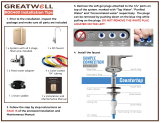
1 On the nipple on top of the tank, apply plumber’s
tape 4 or 5 times clockwise around in the same
direction as the threads.
2 Hand tighten the tank connector onto the tank
nipple until secure. NOTE: Do not cross thread or
over tighten.
3 Using mount stand, place tank near the system
manifold. Measure ⁄" white tubing to the outlet
side of the system manifold and ensure you
have enough tubing to connect tank and system
manifold as well as enough left to attach faucet
stem and remineralizer. Cut ⁄" white tubing.
Stage
RO Membrane
AQ-RO3-RO
OptimH2O™
OptimH2O™
ABCDE F
OptimH2O™
OptimH2O™
OptimH2O™
AB C
2
1
INSTALL SYSTEM MANIFOLD
1 Select an easily accessible area under the sink to mount system
manifold and remineralizer holder. You want to allow at least a 4
to 6 inch clearance below the filters to the floor to allow ample
space for filter changes. To help gauge the right location for your
system manifold, insert first and third stage filter sumps into
manifold. Insert sumps by aligning top connection points and
push up and to the right until sumps are locked in.
2 Mark wall placement for mounting screws using
built-in bracket on back of manifold. Make sure holes
are as level as possible. Mark screw placement of
the remineralizer holder 1 or 2 inches from the third
stage sump to the right of the manifold.
3 Drill two pilot holes for mounting brackets using ⁄"
drill bit for the system manifold. NOTE: Use caution
not to drill into anything beyond the cabinet wall.
4 Insert mounting screws into the wall leaving approximately ⁄" of each screw exposed.
5 Remove first and third filter sumps from manifold by turning each sump to the left and
pulling down before hanging manifold on wall. Mount manifold on wall and screw in. Be
careful not to over tighten.
6 Screw in remineralizer holder onto wall.
4 Install the ⁄" white tubing to the tank:
A. Push the tubing through the nut, collar and sleeve into the connector.
B. Unscrew the compression nut from the tank connector to ensure that the tubing is
connected all the way through the collar and sleeve.
C. Slide the nut to the threads and tighten with a wrench. Avoid over tightening.
INSTALL WATER STORAGE TANK

INSTALL RO FAUCET
You will need a sink top hole 1" in diameter. If drilling a new hole, ensure faucet body will
mount flat against surface and that there is sufficient tubing between faucet body and system
manifold. NOTE: Drilling holes into solid surfaces or surfaces made of stone should only be
performed by a qualified and certified installer.
1 Place the black rubber gasket into the groove of the faucet base and feed the tubing and
faucet threads through the countertop hole.
2 Underneath counter, slide on the slotted washer, spacer and nut. Tighten with wrench.
3 Tighten the white quick connector onto the base of the faucet threads.
4 Attach ⁄" white tubing by inserting into quick connector approximately ⁄" until it stops.
Gently tug on the tubing to ensure it is firmly seated in fitting.
NOTE: Do not connect ⁄" white tubing from tank to faucet.
INSTALL RO DRAIN CONNECTOR
WARNING
CAUTION
Be sure that all electrical appliances and
outlets are turned o at the circuit breaker
before working in the cabinet area.
Please wear safety
glasses to protect
eyes when drilling.
1 Identify drain outlet location. Do NOT install the drain connector onto the same drain pipe
as the garbage disposal whenever possible.
2 Remove protective cover from back of foam seal.
3 Knock center hole out, align holes, and attach to front plate of drain connector.
4 Allowing room for drilling, position the drain connector on sink drain pipe above drain trap.
5 Securely tighten nuts and screws.
6 Using the drain connector port as a drill guide, drill a ⁄" hole into the drain pipe. Be sure
not to penetrate opposite side of pipe, or to damage side of the drain port fitting.
COLDHOT
gasket
washer
quick connector
spacer
nut
drain pipe
bracket
new hole
Pro Tip
If there is leakage from the
drain bracket, loosen the bolts
and slide the bracket up so the
drilled hole is at the bottom of
the drain connector port.

WARNING:
Faucet will leak
if restrictor is
not installed
CONNECT TUBING
I: Brass Tee to Manifold “INLET” (¼" white tubing)
1 Take the white tubing leading from the brass tee and insert it into the manifold port
labeled “INLET”. Remember to push it all the way in until it stops.
II: Manifold to Remineralizer (⁄" red tubing included in packaging)
1 Insert one end into the manifold port labeled “FAUCET”.
2 Insert the other end into the remineralizer port labeled “INLET”.
III: Remineralizer to Faucet (⁄" white tubing already attached to faucet)
1 Insert the ⁄" white tubing (that was installed in step 4) from the faucet into the
remineralizer port labeled “OUTLET”.
IV: Manifold to Tank (⁄" white tubing already attached to tank)
1 Take the white tubing leading from the storage tank and
insert it into the manifold port labeled “TANK”. Remember
to push it all the way in until it stops.
V: Air Gap to RO Membrane (¼" red tubing from faucet)
1 Insert restrictor into the end of the red tubing.
2 Attach ¼" red tubing to the ° elbow until it stops.
3 Attach ¼" ° elbow to the membrane drain port.
VI: Faucet to Drain Connector (⁄" red tubing from faucet)
1 Take the ⁄" red tubing from faucet and insert it all
the way into the drain connector.
COLDHOT
Hose Connections:
¼" White Brass Tee to Manifold
⁄" Red Manifold to Remineralizer
⁄" White Remineralizer to Faucet
I
I
II
III
⁄" White Manifold to Tank
¼" Red Membrane to Faucet
⁄" Red Faucet to Drain Connector
IV
V
VI
V
II
IV
III
VI
OptimH2O™
Stage
RO Membrane
AQ-RO3-RO
OptimH2O™
OptimH2O™
Remineralizer
AQ-RO3-RM
123
0.95"
Tube Marking Guide:
(actual size)
Tubing Dont’s
DO NOT cut tubing too short. Always double check
measurements before cutting.
DO NOT bend or crimp or kink tubing.
DO NOT discard excess tubing.
Tubing Do’s
Insert tubing ALL THE WAY IN to prevent
leaking. In most cases, up to nearly a full inch.
Wet end of tubing to more easily insert into all
inlets and outlets.
Cut excess tubing in order to prevent crimping,
kinks, loops or folds.

SANITIZE, TEST & PURGE
Sanitize
Note: Sanitization is recommended immediately after RO Filter System installation and any inner-part
servicing. The person sanitizing should have clean hands during this process.
1 Shut o water supply to RO system.
2 Open faucet. If tank is not empty, allow to
drain until empty.
3 With included eyedropper and household
bleach (5.25%), disconnect white tubing
from the manifold outlet labeled “TANK”.
Note: Bleach needs to be handled
according to manufacturer’s instructions.
4 Add 3ml bleach into open end of tank white
tubing.
5 Reconnect the tank from the tube into the
manifold outlet labeled “TANK”. Be sure to
push tubing in all the way.
6 Sanitation will be completed during the following pressure test and purge. Important:
Bleach must be completely removed from system before drinking water. See Purge
instructions below.
Pressure Test
Important: Complete sanitization prior to pressure test.
1 Open cold water supply valve to RO Filter System.
2 To purge air from the plumbing system, open kitchen faucet. Close faucet when water runs
smooth.
3 Confirm RO faucet is closed.
4 Within approximately 2 hours, pressure will start to build in the RO Filter System. Carefully
inspect all connections and fittings while this pressure buildup occurs.
5 Check for leaks. If leaks are found, fix by ensuring all tubing is cut squarely and fully inserted.
Also confirm there are no scratches, dents or notches at tubing end. If there are, squarely cut
1" o and re-insert.
Note: When RO Filter System is first pressurized, water may project
from faucet air gap hole until air is passed from RO Filter System.
Purge
1 Open RO faucet and let water flow through system for 24 hours.
Note: Flow rate will be slow during this time.
2 Close RO faucet after purge is complete.
Note: Your RO Filter System is ready for use when purge is complete, however, you will not have filtered
water immediately. It takes 1-3 hours to completely fill the tank. The flow rate will be less than your
kitchen faucet. Water will run to the drain while the RO Filter System is filtering water – even when not in
use. This is normal. Water going to drain will stop automatically when tank is at capacity.
STEP FILTER INSTALLATION
Before you begin: make sure the cold water valve is shut off and there is no pressure in the system. Carbon
(red) and Claryum (yellow) filter cartridges will come pre-installed in their cartridge sumps.
1 Attach red carbon sump to the 1st stage position on the inlet side of the system manifold.
Make sure all connection points are aligned and push the top of the sump up and into the
system manifold. Turn it towards the right until it locks in.
2 Repeat step 1 for the 2nd Stage RO membrane that goes in the center, and for the yellow
Claryum cartridge in the 3rd stage position on the outlet side of the system manifold.
Be sure to turn 2nd stage RO membrane all the way to the right, until drain port on cartridge is
facing the rear of the system.
OptimH2O™
Stage
RO Membrane
AQ-RO3-RO
OptimH2O™
OptimH2O™
Remineralizer
AQ-RO3-RM
2
1
2
1
2
1
/